Search results
Query: mini coax
Links: 47 | Categories: 0
-
 The 160/80m coaxial receiving loop antennas are designed to enhance reception on the top bands while minimizing noise. These antennas are particularly beneficial for operators with limited space, as they can be constructed using lightweight materials, making them portable and easy to deploy. The standalone 80m loop has a diameter of approximately four feet, allowing for easy rotation and installation above existing VHF antennas. Over the years, many amateur radio operators have turned to loop antennas as a viable alternative to traditional beverage antennas. The design allows for significant noise reduction, especially when paired with a quality pre-amplifier. Experimentation with various configurations has led to the discovery that diamond-shaped loops provide optimal performance. Users have reported a noticeable improvement in signal quality, making these loops a valuable addition to any low-band DXing setup.
 -
 Demonstrates the construction of **magnetic loop antennas**, detailing both multi-turn and single-turn designs. It covers a 30-inch diameter multi-turn loop for 80 meters, based on a February 1996 QST article, and an octagon single-turn loop made from 15mm copper tube with a 4.8-meter circumference, operating from 7 MHz to 14 MHz. The document also presents a smaller 800mm diameter loop for 14 MHz to 28 MHz, emphasizing the importance of high-voltage tuning capacitors. Covers the design and construction of custom **butterfly capacitors** and piston capacitors, including a split stator capacitor with 140 pF capacitance and a 6000 Volt rating, and a butterfly capacitor with 5-65 pF and 7200 Volt rating. It explains why butterfly capacitors are preferred over split stator types for high power applications due to lower losses and direct series connection of rotors, reducing resistive losses from wiper contacts. Material recommendations include clear PVC for plates and brass or stainless steel for non-magnetic hardware. Addresses practical considerations such as feeding the loop with a shielded 1/5 Faraday loop made from RG213 or RG8 coax, achieving VSWR 1.1 across bands, and optimizing its placement 180° from the capacitor. It also discusses mechanical joint resistance, dissimilar metal oxidation prevention using Vaseline, and a simple method for determining radiation angle with a TL-light tube. The guide includes diagrams for rotor, stator, and end plate construction.
 -
 The Little Stick antenna is an aluminium version of the Vertical Bazooka design which was made from coax.
 -
 Determining the actual need for an antenna tuner often hinges on the specific antenna and feed line configuration in use. While many hams believe a tuner is always essential, its primary role is to present a 50-ohm impedance to the transceiver, not to "tune" the antenna itself. For instance, a resonant dipole fed with _coaxial cable_ at its design frequency typically requires no tuner, as the feed line impedance closely matches the radio's output. However, operating a non-resonant antenna, or using a resonant antenna on multiple bands, frequently necessitates a tuner to manage high Standing Wave Ratio (SWR) on the feed line. The article clarifies that a tuner placed at the transceiver only matches the radio to the feed line, not the antenna to the feed line. For maximum efficiency with a non-resonant antenna, an _automatic antenna tuner_ (ATU) or a remote tuner placed at the antenna feed point is often more effective, minimizing losses in the feed line. The discussion also touches on the practical implications of SWR, noting that modern transceivers often fold back power at high SWR, making a tuner a practical necessity to achieve full output power, even if the antenna itself is not perfectly matched.
 -
 Details the construction and optimization of antenna systems for amateur radio satellite operations, focusing on practical, homebrew solutions for VHF/UHF bands. It covers building _groundplane antennas_ from salvaged materials, recycling old beam antennas into new configurations like a 2-meter crossed yagi, and constructing a 10-meter horizontal delta loop. The resource also explains antenna matching techniques, including folded dipole driven elements and quarter-wave transformers, along with the importance of accurate SWR measurements and minimizing coax loss. Demonstrates how to achieve a **1:1 SWR** by carefully trimming elements and adjusting radial angles on groundplane antennas. It provides insights into selecting appropriate coax and connectors, highlighting the benefits of Belden 9913 for low loss and the proper installation of _N-connectors_. The article also addresses RFI mitigation from computer birdies and presents a design for a silent triac antenna control circuit, offering practical solutions for common satellite station challenges.
 -
 This article describes how to make a quadrifilar helix (QFH) antenna easily, from inexpensive materials: uPVC plumbing pipe and RG-58U co-axial cable. A low-cost, easy-to-build Quadrifilar Helix (QFH) antenna for weather satellite reception using uPVC plumbing pipe and RG-58U coaxial cable. Unlike traditional designs requiring copper pipe and plumbing skills, this approach enables construction with basic tools and minimal technical expertise. The antenna's shorter, wider proportions favor higher elevation angles, reducing interference from horizon-level pager transmitters. Electrical connections are simplified at the antenna's apex, with the coaxial cable forming the radiating elements. Testing demonstrated consistent signal strength throughout satellite passes, proving effective weather satellite reception is achievable without precision engineering to sub-millimeter tolerances.
 -
 Presents detailed plans and construction notes for a compact 3-element Yagi antenna specifically designed for the 50 MHz band, authored by Ken Willis, _G8VR_. The article, originally published in _Practical Wireless_ in 1989 and updated in 1999, outlines the design philosophy behind a small, gain-oriented antenna suitable for restricted QTHs. It covers element dimensions, boom length, and a unique coaxial _gamma match_ system, emphasizing a "plumber's delight" construction approach using readily available hardware. The resource details the author's operational experience, achieving _DXCC_ on 50 MHz with over 110 countries worked using this antenna. It also incorporates insights from computer simulation studies by _G3SEK_ and _W1XP_ using _MININEC_, which suggested minor adjustments to element lengths and spacing for improved front-to-back ratio, increasing it from 14dB to 31dB. The author compares theoretical performance with practical results, noting that while larger arrays might offer a few dB more gain, this compact design provides excellent performance for F2 propagation and general 6-meter DXing.
 -
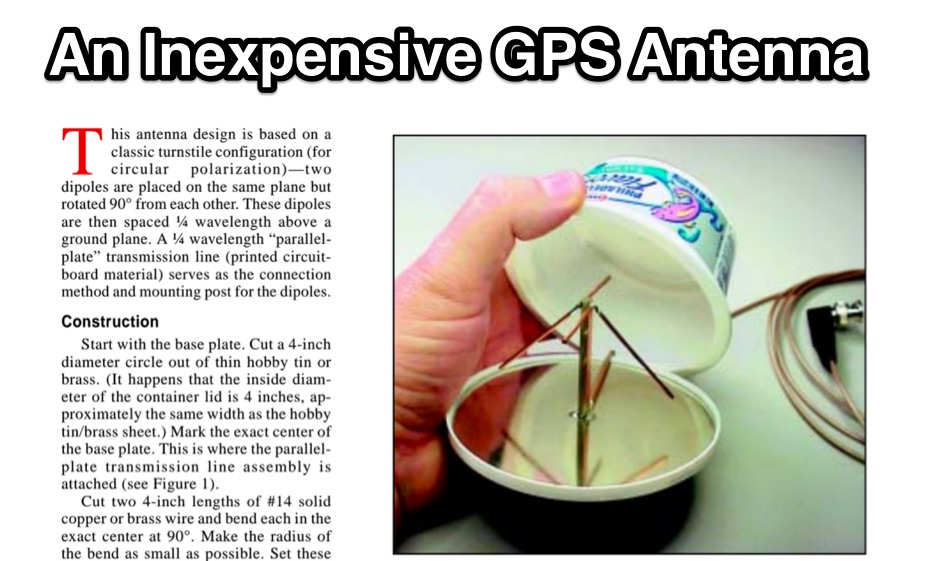 For amateur radio operators utilizing _APRS_ or requiring an external antenna for their GPS receiver, this resource details the construction of a compact, circularly polarized mobile antenna. The design is based on a classic turnstile configuration, employing two dipoles rotated 90° from each other and spaced a quarter-wavelength above a ground plane. A parallel-plate transmission line, fabricated from printed circuit board material, serves as both the connection method and mounting post for the dipoles, simplifying the feed network for circular polarization at 1.57542 GHz. The article outlines the fabrication process, starting with a 4-inch diameter hobby tin or brass base plate and #14 solid copper wire elements. It specifies using _RG-58/U_ or similar 50-ohm coax, with an 8-foot maximum length to minimize loss at the GPS frequency. The parallel-plate transmission line is constructed from two 2-inch lengths of single-sided _FR-4_ or G10 PCB material, 0.062-inch thick, with a specific 45° microwave turn cut on the active side. Final assembly involves an 8-ounce cream cheese container as a radome, and the article discusses the self-phased quadrature feed method to achieve circular polarization without a coaxial phasing line, resulting in an omnidirectional pattern suitable for GPS satellite reception.
 -
 Building a directional antenna for limited space, M0MRR shares his experience constructing a 10-meter Moxon rectangle. Initially using fiberglass fishing poles and a plastic breadboard, he achieved a 1:1.2 SWR across the band with 50 watts, making contacts as far as PY2TO from the UK. The design incorporates 10-amp power cable for elements and RG58 coax with crocodile clips for feeding, demonstrating a cost-effective approach. His field observations confirm the directional properties, noting European signals fading when facing Stateside, and receiving better reports from stations in the antenna's favored direction. While not formally measured, the front-to-back ratio appears effective. The initial build was somewhat flimsy, intended for temporary deployment, but proved effective for DX. Later, M0MRR constructed a more robust 10-meter Moxon using tubular aluminum pipe, indicating an evolution in his design approach for durability. The project highlights practical antenna building for small backyards, emphasizing the benefits of a directional antenna even with modest power.
 -
 The 80-meter loop antenna, measuring 86 meters (282 feet) of wire, effectively operates across 8 HF bands from 80 through 10 meters, despite its length being a compromise for specific bands. This design prioritizes a "low enough" SWR across multiple bands, aiming for lower SWR values on higher frequencies due to increased feedline losses. A 200-ohm feedpoint impedance provides a workable SWR on every band, with feedpoint impedances ranging from 100 ohms for lower bands to 300 ohms for higher bands. Radiation patterns for the 80-meter loop, mounted at 15 meters high, show a maximum gain of 7.6 dBi at a 90-degree takeoff angle on 80 meters, and up to 12.9 dBi at a 10-degree takeoff angle on 12 meters. This configuration supports regional contacts on 80 meters and provides good DX performance on higher bands. Practical construction notes emphasize using robust supports like trees, ensuring wire slack with _egg insulators_ for wind resilience, and employing an oversized 2 kW 4:1 _balun_ to safely handle higher SWR conditions, even with 100W transceivers. Feedline losses are minimized using _LMR-400_ coax or ladder line, with power transfer efficiency between 80% and 95%. Antenna simulations were performed using _xnec2c_, and the provided NEC file is compatible with other NEC2 derivatives. The antenna is tunable on 6 of 8 bands with an internal ATU and all 8 bands with an external autotuner like the LDG AT-200 Pro.
 -
 A 10-meter J-Pole antenna, detailed in QST February 1950, offers a straightforward solution for hams operating with restricted space. This design, originally presented by W1BLR, is a **half-wave radiator** fed by a quarter-wave matching stub, providing a low-angle radiation pattern beneficial for DX. The article describes building the antenna from readily available materials like copper pipe, emphasizing its simplicity and effectiveness for **single-band operation**. The J-Pole's inherent design provides a good impedance match to 50-ohm coaxial cable without the need for an external tuner, a significant advantage for portable or minimalist stations. Its nondirectional pattern ensures coverage in all directions, making it a versatile choice for general operating on the 28 MHz band. The construction plans are clear, allowing even those with basic workshop skills to assemble a functional antenna.
 -
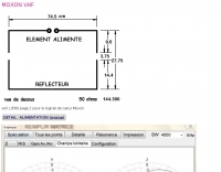 Details the construction of a portable _Moxon_ antenna optimized for the 2-meter band, utilizing readily available materials like 6.5 mm aluminum elements and a 15x15 mm TV boom. The design emphasizes ease of assembly and portability, making it suitable for field operations. Performance specifications derived from MMANA modeling indicate a forward gain of **6.3 dBi** and a front-to-back ratio of **15 dB**. Lateral attenuation is reported at 40 dB, with a minimum SWR of 1.1 at 144.300 MHz, confirming efficient operation within the target frequency segment. The antenna is lightweight at 500 grams, quickly assembled in approximately two hours, and disassembles into a compact 40x15x8 cm package. Direct feeding with RG-58 C/U or KX-15 coaxial cable via a BNC connector simplifies deployment.
 -
 Details a practical QRP wattmeter construction, leveraging a simplified SWR meter design by JA6HIC. The project focuses on a forward-only power measurement circuit, providing a functional instrument for RF power levels from milliwatts up to 5 watts. It maintains a 50-ohm input and output impedance, suitable for typical QRP transceivers and antenna systems. The resource includes the schematic for the "VSW" (Very Simple Wattmeter) and outlines a six-step alignment procedure. This calibration process involves using a known RF source up to 5W, setting full-scale deflection, and marking power increments. It also addresses minimizing frequency effects on readings with a 100pF trimmer capacitor, noting that measurement error is highest at the lower end of the scale. Construction notes mention using a piece of RG-213 coaxial cable for the inductance and coupler, with the wattmeter assembled in early 2003. The author provides an example measurement showing 0.8W into a dummy load and 1W into a 3-element beam.
 -

-
 Constructing a compact UHF Moxon antenna for portable radio or TV applications demands a small, easily transportable aerial. This project focuses on a straightforward build method rather than a specific frequency design, leveraging _MoxGen_ software by AC6LA to derive precise dimensions. The author's approach utilizes an epoxy printed circuit board as the support, with traces drawn by a special felt-tip pen for soldering the antenna elements after an etching bath. For high-frequency work, particularly in the GHz range, the choice of insulating material is critical; the article emphasizes the necessity of quality UHF or SHF-grade insulation. A standard SMA connector is integrated, with one element making electrical contact via the nut and the other soldered to the central pin. This ensures a robust feedpoint for the coaxial cable. The coaxial cable, fitted with its connector, is threaded through a 12mm PVC tube that functions as a mini-mast. This tube also defines the antenna's forward direction, which should be aimed at the target signal. A sanitary clamp at the base of the tube secures it to a photographic tripod via its 7mm thread, providing a stable and portable mounting solution.
 -
 A 5/8 wavelength mobile whip antenna for 2 meters can be constructed from a 5-foot CB helical whip, requiring the removal of original wire and installation of a new radiating element made from coax braid. The design incorporates an 8-turn loading coil with 5mm spacing, fabricated from the original whip wire, and utilizes approximately 1400mm of RG-58 coax braid for the radiating element to enhance flexibility and bandwidth. Final whip length is approximately **1350mm** from base to braid end, with tuning adjustments made by trimming the braid. Dual-wall 12mm heat shrink, such as _Jaycar WH5643_, is recommended for weatherproofing and stabilization, costing around $4.50 per 1200mm length. Achieving a 1.1:1 VSWR may not be feasible; a 1.5:1 VSWR is considered acceptable. Optimal mobile mounting is centered on the vehicle roof to minimize radiation pattern variations.
 -
 A GSM1800 Moxon Square antenna project is presented, detailing its construction using three 1.5mm copper wire pieces for the reflector and dipole elements. The design inherently offers a 50-ohm feedpoint impedance, allowing direct connection to 50-ohm coax without complex matching networks like baluns or gamma matches, which are prone to high attenuation at 1.8 GHz if not precisely built. The resource includes a construction plan, expected **SWR plots**, and **radiation patterns** for the GSM 1800 band, specifically covering the 1710-1785 MHz transmit (red zone) and 1805-1880 MHz receive (blue zone) segments. The SWR remains below 2:1 across the entire GSM 1800 band, with the main lobe consistently achieving 5-6 dBi gain. While the radiation pattern shows some changes across the band, these primarily affect the back of the antenna, maintaining consistent forward gain. Practical considerations for high-frequency operation are emphasized, such as minimizing coax length (e.g., under 1 meter for RG-174) and selecting appropriate connectors like N, SMA, or BNC to mitigate significant attenuation. The article also discusses direct connection to the phone's RF PCB for minimal loss and notes observed signal strength variations with antenna orientation despite crossed polarization at cell sites.
 -
 Demonstrates the design and construction of a compact, portable multi-band mini-delta loop antenna, specifically optimized for /P (portable) operations from remote locations like Scottish islands. The resource covers the theoretical underpinnings of half-wave loops, contrasting closed and open configurations, and then details the application of a folded dipole principle to achieve a 50-ohm match for direct coax feed. It presents empirical formulas for calculating element lengths, considering the velocity factor of common wire types, and provides a detailed example for a 20m (14.175 MHz) version. The article includes a comprehensive table of dimensions and allowances for a five-band (20m, 17m, 15m, 12m, 10m) mini-delta beam, along with construction hints for the central support and balun. It specifies a 1:1 trifilar balun wound on a ferrite rod and describes the antenna adjustment process using an _MFJ-259B Antenna Analyser_. Initial test results indicate an SWR of 1:1 at resonance and a bandwidth of approximately 240 kHz on 20m, even at a low height of five feet above ground. The distinctive utility lies in its focus on a practical, easily deployable beam antenna for portable DXing, offering a viable alternative to more complex or larger arrays.
 -
 Accurately determining an antenna's feedpoint impedance is crucial for optimal performance, especially when experimenting with new designs or making adjustments. While SWR meters provide basic information, a full complex impedance measurement reveals the resistive and reactive components, which are essential for proper matching. Modern antenna analyzers, like the _Palstar ZM30_ or MFJ259B, simplify this task, but measurements taken through a transmission line require careful interpretation due to impedance transformation. This resource details a calibration method to precisely account for the effects of the feedline. It explains how a transmission line can significantly alter the measured impedance, illustrating this phenomenon with a Smith Chart example where an 80m antenna's [22 + j6] Ohms feedpoint impedance transforms to [82 + j45] Ohms after a 10m line. The guide demonstrates using a transmission line calculator applet, such as the one by W9CF, to reverse this transformation. It outlines the process of calibrating a specific length of RG174 coax, showing how an initial 26ft estimate was refined to **25.85ft** to accurately predict a known 22 Ohm load, significantly improving accuracy over uncalibrated results.
 -
 Demonstrates the operational status and reception reports for the SK6RUD/SA6RR QRPP beacons, which transmit on 478.9 kHz, 1995 kHz, 10.131 MHz, and 40.673 MHz. These beacons utilize extremely low power, with the 630-meter beacon operating at approximately 0.1 watt ERP into an L-antenna, showcasing the potential for long-distance contacts under favorable propagation conditions. The site details the specific frequencies and antenna types employed, such as a vertical at 500 kHz and a 1/4 vertical for higher bands. The resource compiles over 10,530 reception reports from amateur radio operators worldwide, logging details such as date, time, band, RST signal report, locator, distance, and receiver setup. Notable long-distance reports include a 500 kHz reception by AA1A-Dave from 5832 km in 2008 and a 10.133 MHz reception by ZL2FT-Jason from 17680 km in 2010, illustrating the global reach of these low-power transmissions. Each log entry provides specific equipment used by the reporting station, including transceivers like the Yaesu FT817, ICOM IC-7300, and various antenna configurations such as coaxial mag loops, inverted Ls, and end-fed wires. The primary objective of the SK6RUD beacons is to challenge conventional notions of power requirements for effective two-way communication, proving that contacts over significant distances are achievable with minimal output. The site also includes a submission form for new reception reports, fostering community engagement and continuous data collection on propagation phenomena across different bands. The detailed logs offer practical insights into real-world propagation characteristics and the efficacy of QRPP operations.
 -
 Designing and constructing portable wire antennas for HF operations, this resource explores several configurations including the _foldback dipole_ for space-constrained setups and an inductively shortened dual-band dipole for 20m and 40m. It details the calculation of inductance for shortened elements, providing a Visual Basic 6.0 program screenshot that illustrates determining coil parameters like turns and length for a **25.5 uH** inductor. The document emphasizes practical considerations such as adjusting wire lengths for optimal SWR, noting that a dual-band dipole achieved SWR below 2:1 on both 20m and 40m, with careful adjustment bringing it under 1.5:1. Further, the resource describes a half-wave antenna matched with a coaxial stub, a method often referred to as the _Fuchskreis_ in German amateur radio circles, to transform the high feedpoint impedance to 50 Ohms. This monoband solution, for a 20m application, uses a stub length of **2.98m** (0.216 lambda multiplied by coax velocity factor) and a shorted stub of approximately 48cm. The coaxial stub design is highlighted for its resilience to ground proximity, allowing it to be rolled up or laid on the ground with minimal SWR impact, making it highly suitable for portable QRP operations.
 -
 Presents a construction project for a 1:1 current balun, specifically detailing the _Sorbie Balun and Bottle Choke_ design. The resource outlines the winding technique, employing 4+4 turns of mini coaxial cable on a large ferrite core, and provides insights into the physical assembly. It includes specific material recommendations, such as the type of ferrite and coaxial cable, crucial for achieving the desired impedance transformation and common-mode current suppression. The content covers the practical steps involved in building the balun, from preparing the coaxial cable to securing the windings on the ferrite toroid. It also discusses the integration of the balun into an antenna system, emphasizing its role in maintaining pattern integrity and reducing RF interference in the shack. The resource offers a clear, step-by-step approach, making the project accessible for homebrewers. Illustrations and photographs accompany the text, visually guiding the builder through each stage of construction. The article concludes with performance expectations and considerations for deployment, ensuring the constructed balun functions effectively across the intended frequency range.
 -
 PL-259, Motorola & N connectors, Coax Seal, universal adapter kit, TNC, Mini-UHF, SMA, F & BNC connectors, audio connectors,antenna mounts and antennas
 -
 Operating a ham station often involves encountering radio frequency interference (RFI), RF feedback, or RF burns, which are frequently misattributed to poor equipment grounding. This resource meticulously dissects these assumptions, asserting that RF grounds on the operating desk often merely mask more significant system flaws. It identifies five primary causes for RF problems, including antenna system design flaws, proximity of the antenna to the operating position, DC power supply ground loops, equipment design defects, and poorly installed connectors or defective cables. The content emphasizes that issues like "hot cabinets" or changes in SWR when connecting a ground indicate substantial RF flowing over wiring or cabinets, a phenomenon known as common-mode current. The article provides detailed explanations of common-mode current generation, particularly from single-wire fed antennas like longwires, random wires, and OCF dipoles, which inherently present high levels of RF in the shack. It also illustrates how vertical antennas, lacking a perfect ground system, can excite feed lines with significant common-mode current. Through simulations, the author demonstrates how a dipole without a proper _balun_ can cause RF problems at the operating desk, showing current patterns and voltage distributions on feed line shields. The discussion extends to the proper application of _RF isolators_ and _ferrite beads_, clarifying their role in modifying common-mode impedance on cable shields and cautioning against their use as a band-aid for fundamental system defects. The resource advocates for correcting the actual source of RF problems, such as antenna system issues or poor connector mounting, rather than relying on internal shack grounding or isolators. It highlights that properly functioning two-conductor feed lines, like coaxial or open-wire lines, should result in minimal RF levels at the operating position, even without a desk RF ground. The author shares personal experience, noting that his stations since the late 1970s have operated without RF grounds at the desks, relying instead on proper antenna system design and feed line integrity.
 -
 1.5 dB of matched line loss can be calculated for a given transmission line using this online tool, which employs a model calibrated from empirical data. The calculator allows radio amateurs to input specific transmission line types, such as _RG-8_ or _RG-58_, and then determine the expected signal attenuation. This is crucial for optimizing antenna system efficiency and understanding power delivery to the radiating element, especially for HF and VHF operations where feedline losses can significantly impact performance. Beyond matched loss, the calculator also provides an estimate for mismatched loss if the Standing Wave Ratio (SWR) is specified. This feature helps operators quantify the additional power loss due to impedance discontinuities between the transceiver, feedline, and antenna, which is a common concern in amateur radio installations. Accurate loss calculations are vital for effective station design and for predicting actual radiated power. The tool's utility extends to various operating scenarios, from fixed station setups to portable deployments, aiding in the selection of appropriate feedline lengths and types to minimize signal degradation. Understanding these losses is a fundamental aspect of maximizing the effectiveness of any amateur radio antenna system.
 -
 A 50.200 MHz Moxon antenna for the 6-meter band is detailed, providing practical construction guidance for amateur radio operators. The design utilizes 3/4" aluminum angle stock for the elements, joined with wood molding and 1/4 x 20 hardware. Key components include an SO-239 connector for the feedpoint and a **choke balun** made from coiled RG-58 coax, ensuring proper impedance matching and minimizing common mode current. The antenna measures approximately 29 inches deep by just under 7 feet long, making it suitable for portable operations. Specific dimensions, based on **Cebik's nomenclature**, are provided for the driven element and reflector. The resource also offers modeling hints, suggesting an effective element diameter of 1 inch for software simulations and emphasizing element sizing based on corner screws rather than end-to-end measurements.
 -
 Coaxial cable stripping for PL-259 connectors requires precise measurements to ensure optimal RF performance and mechanical integrity. For RG-8X, the outer jacket is stripped 1/2 inch, the braid 5/16 inch, and the dielectric 1/8 inch, leaving the center conductor exposed. RG-58 preparation involves a 1/2 inch jacket strip, 1/4 inch braid strip, and 1/8 inch dielectric strip. These specific dimensions facilitate proper soldering and crimping, minimizing impedance discontinuities at the connector interface. Different coaxial cable types, such as RG-8 and RG-213, necessitate varied stripping lengths due to their construction. The _PL-259_ connector, a common UHF type, relies on these exact preparations for a secure fit and low-loss connection. Incorrect stripping can lead to high SWR, RF leakage, and mechanical failure, impacting overall station efficiency. The guide details these critical dimensions for several popular coax cables. Using a dedicated _coax stripper_ tool or precise measurements with a utility knife improves consistency.
 -
 Voldatech, a manufacturer based in China, produces a range of RF feeder cables and site components essential for amateur radio installations and telecommunication infrastructure. Their product line includes various types of coaxial cables, such as **50 Ohm** and 75 Ohm options, along with a comprehensive selection of connectors like N-type, UHF, and BNC. These components are critical for maintaining signal integrity and minimizing loss in antenna systems, whether for a home shack or a remote DXpedition setup. The company's focus on _RF Coax cables_ and connectors directly supports the needs of radio amateurs seeking reliable transmission lines for their transceivers and antennas. Amateurs often compare Voldatech's offerings to established brands, evaluating factors such as impedance matching, shielding effectiveness, and durability under various environmental conditions. The availability of diverse cable types allows operators to select optimal solutions for different frequency bands and power levels, from QRP to high-power amplifier setups. Their products are particularly relevant for those constructing new antenna arrays or upgrading existing feedline systems, aiming to achieve maximum power transfer and reduce standing wave ratio (SWR) for efficient signal propagation.
 -
 Enables Android users to operate various _miniVNA_ antenna analyzers via Bluetooth, USB, or Wi-Fi, providing a portable solution for RF measurements. The application supports full control over data acquisition, offering features like custom frequency range selection from 1 KHz to the VNA's full range, and automatic screen adaptation for diverse Android device resolutions. It facilitates intuitive, wizard-based calibration for both reflection and transmission modes, saving calibration data for different VNA types (Standard, Pro, Pro with Extender) to avoid repeated procedures. The software displays critical parameters such as SWR, |Z|, Return Loss, Phase, Rs, and |Xs| on 2-axis graphs or Smith charts, with multi-touch gestures for zoom and frequency shift. It includes a frequency generator mode with independent channels and attenuator control for the miniVNA Pro, along with a sweeper function. The cable data mode automatically calculates phase and loss, measures cable length from less than 1 meter to hundreds of meters, and includes a table of common coax cable velocity factors. An experimental X-tal mode measures resonance frequency, Rs, and Q. Data export options include CSV, ZPLOT, and S1P formats, with CSV import capability. The application also features an SM6ENG Audio mode for SWR tuning without visual reference and provides a miniVNA battery voltage indicator. It supports a wide frequency range, with the miniVNA Extender extending coverage up to **1500 MHz**. The application is compatible with Android version 2.2 and later, tested on devices like the _Galaxy TAB 7.7 P6800_.
 -
 Determining the characteristic impedance (Z) of an unknown coaxial cable, a common challenge for many radio amateurs, can be resolved with a straightforward method. The impedance of a coaxial cable is derived from its inductance and capacitance, and importantly, these values are independent of the cable's length or the operating frequency. This means that measuring a random length of cable, such as 20 meters, provides sufficient data for calculation. The core of this technique involves an LC-meter to obtain the inductance (L) in microHenries (uH) and capacitance (C) in microFarads (uF). The impedance is then calculated using the formula Z = L/C. For instance, a measurement yielding L=1.2uH and C=450pF (0.00045 uF) results in an impedance of 51.6 Ohms, closely matching **RG-58** specifications. Similarly, a TV coaxial cable with L=1.8uH and C=320pF (0.00032 uF) calculates to 75 Ohms. While the accuracy of this method, depending on the LC-meter's tolerance, is approximately 10%, it proves sufficiently precise for practical determination of unknown coaxial cable impedance, as noted by Makis, SV1BSX, who credits Cliff, K7RR, for the formula's dissemination.
 -
 Messi & Paoloni offers a range of RF coaxial cables, including the _Ultraflex_ series, specifically engineered for amateur radio applications. These cables feature advanced dielectric materials and high-density braiding, resulting in significantly reduced attenuation across HF, VHF, and UHF bands. For instance, the Ultraflex 7 exhibits a loss of only **2.5 dB per 100 feet** at 144 MHz, making it suitable for demanding DX and contesting operations. The company's product line also includes specialized connectors, such as N-type and PL-259, designed to maintain optimal impedance matching and minimize signal reflections. Each connector is precision-machined to ensure a secure, weather-resistant termination, crucial for outdoor antenna installations and long-term reliability. Messi & Paoloni emphasizes rigorous quality control, with all cables undergoing testing to ensure consistent performance and durability, supporting effective two-way radio communication.
 -
 Constructing a dual-band antenna for 40 and 20 meters often involves compromises in size or complexity. This resource presents a compact _open sleeve dipole_ design that addresses these challenges by using 450-ohm ladder line and folded elements to achieve a total length of approximately **17.17 meters**, significantly shorter than a full-size 40-meter dipole. The design leverages electromagnetic coupling, where a primary radiator handles the 40-meter band, and a second conductor resonates on 20 meters without direct electrical connection. This configuration eliminates the need for traditional traps, loading coils, or switching components, simplifying construction and reducing potential loss points. The antenna is fed with RG-58C/U coaxial cable, and a common-mode choke is recommended at the feed point to suppress sheath currents, ensuring a cleaner radiation pattern and minimizing RF in the shack. The design is well-suited for portable operations, field deployments, temporary installations, and restricted urban environments where space is a premium, offering solid performance on both HF bands.
 -
 Details Amphenol Connex's product range, focusing on RF connectors, adapters, and cable assemblies. The company produces common radio frequency interfaces such as _BNC_, _SMA_, and _TNC_ connectors, alongside numerous other specialized designs. These components are critical for establishing reliable signal paths in amateur radio stations, ensuring proper impedance matching and minimal signal loss across various frequency bands. The manufacturing process emphasizes precision engineering to meet the demanding specifications of RF applications, from HF to microwave frequencies. Product lines support diverse coaxial cable types, facilitating custom cable assembly for specific station configurations. The extensive catalog provides solutions for both fixed station installations and portable operations, addressing the needs of contesters, DXers, and general amateur radio operators.
 -
 A Lightweight 2m Yagi for SOTA. The boom is 20mm PVC electrical conduit and the elements are 2.4mm aluminium TIG welding rod. The antenna is carried as a single length of conduit with the elements stowed inside the boom, sealing them in with a bung. The driven element is connected directly to 50 Ohm coax with a BN-43-202 balun core to decouple the coax shield.
 -
 Operating an amateur radio station effectively requires reliable coaxial cable to minimize signal loss between the transceiver and antenna. SIVA Cavi, an Italian manufacturer, produces a range of coaxial cables, including specific 50 Ohm low-loss types suitable for amateur radio applications. Their product line features cables like **RG 58 SHF1**, **RG 213 SHF1**, and **RF 400 SHF1**, which are commonly deployed in HF and VHF/UHF setups. The company also offers specialized cables such as the **HF 214 UF Ultraflex**, a high-performance broadband low-loss 50 Ohm cable designed for flexibility and reduced attenuation across various amateur bands. These cables are engineered with solid or foam dielectric materials, impacting their electrical characteristics and suitability for different power levels and frequency ranges. For instance, foam dielectric cables often exhibit lower loss at higher frequencies, a critical factor for VHF/UHF operations. Beyond amateur radio, SIVA Cavi manufactures cables for digital video broadcast, offshore marine use, and fire detecting systems, demonstrating a broad engineering capability in coaxial cable technology.
 -
 Learn how to easily improve your handheld VHF performance on the 2-meter band with the Flowerpot antenna. This simple DIY antenna made from coaxial cable requires minimal tools and materials, providing a big range upgrade compared to standard rubber-duck antennas. Discover how to build, tune, and optimize the Flowerpot antenna for excellent performance. Ideal for hams looking for lightweight, portable solutions for handhelds, mobile rigs, home stations, SOTA/POTA activations, and emergency communication.
 -
 Operating within the low-frequency spectrum, transformers serve critical roles in antenna systems, particularly for 160m applications. The resource details the construction and performance of 1:1 transformers built on BN-73-202 cores, emphasizing their use as hybrid combiners or phase inverters for RX antenna arrays. Measurements reveal that these transformers exhibit minimal losses, around 0.12 dB at 1.8 MHz, with variations based on wire type and number of turns. The analysis includes comparative data on transformer performance, highlighting the impact of different winding techniques on frequency response. Notably, the use of coaxial cable for winding improves bandwidth while maintaining low-frequency efficiency. The resource also discusses braid breaker transformers, which minimize inter-winding capacitance, achieving low losses around 0.21 dB at 1.8 MHz. These insights are crucial for optimizing low-band antenna systems, allowing operators to make informed decisions regarding transformer design and implementation.
 -
 The mini Radio Solutions miniVNA PRO is the only affordable vector network analyser (VNA) I know of that offers remote wireless operation. This is very interesting because it allows to measure the input impedance of HF antennas installed at height without having to deal with coax cable lengths, baluns nor common mode suppression chokes. However, to render the miniVNA PRO truly field proof, it requires a number of significant modifications.
 -
 The multiband tuned doublet, or center-fed Zepp, is a simple and efficient HF antenna that operates effectively across most amateur bands using a balanced parallel-wire feedline and antenna tuner. Unlike coax-fed dipoles, it tolerates impedance mismatches with minimal loss. By selecting suitable feedline and dipole lengths, one can achieve stable multi-band operation. While it doesn’t match monoband Yagis, it offers excellent performance, low cost, and broad coverage. Its radiation pattern and efficiency vary with frequency, but it remains a practical and versatile solution for HF operators.
 -
 This resource details the construction and performance of a compact broadband magnetic loop antenna designed for portable receiving applications with devices like the _ATS MiniRadio_. The antenna utilizes approximately 3 meters of 0.5–1 mm copper wire wound in two turns on a rhomboidal wooden frame, measuring 50 cm by 70 cm. It connects via a modified 9:1 unun, where the primary center tap is isolated from ground to improve common-mode noise rejection. The design provides untuned operation across a frequency range from the longwave band up to approximately 25 MHz. Performance characteristics include observable directivity for noise suppression and the ability to connect directly to a radio or via a 50 coaxial cable for remote operation. The article specifies the unun's 3:1 turns ratio and its SMA output for connectivity. The methodology focuses on practical construction and observed reception quality.
 -
 Demonstrates the construction of an **ATU-100 (N7DDC)** automatic antenna tuner, detailing the assembly process from component arrival to final enclosure. The resource covers winding the tandem match transformer, connecting the OLED display, and integrating optional control buttons. Specific attention is given to modifying the EEPROM settings for **QRP operation**, reducing the minimum tuning power to 1 Watt, and addressing potential RF interference with CPU by adding capacitors to button connections. The build log includes practical tips such as adapting RG58 coaxial cable strands for PCB mounting and utilizing a repurposed Macbook Pro cover for the custom enclosure. The author references external GitHub pages for comprehensive information, R0AEK's resources for additional details, and a video by MW0SAW for EEPROM configuration across different ATU-100 variants. Future plans involve field testing the completed tuner during SOTA or other portable activations.
 -
 This document provides comprehensive guidance on modeling and constructing multiband dipole antennas using traps. It addresses common segmentation issues in EZNEC modeling software, recommends optimal segment lengths for trap models, and compares trapped dipoles with paralleled multiband dipoles. While trap dipoles are significantly shorter, they exhibit lower gain and narrower bandwidth. Detailed instructions for building weatherproof coaxial traps include material lists, construction steps, and tuning methods. The guide notes that properly constructed coaxial traps introduce only minimal signal loss (0.6 dB) while offering practical multiband performance in a compact design.
 -
 The article by Guy Olinger, K2AV, published in the May/June 2012 National Contest Journal, introduces the Folded Counterpoise (FCP), a compact 516-foot single-wire counterpoise elevated at 8 feet, designed for 160-meter operations on small lots like 100x150-foot backyards. Originating from efforts to revive Top Band for W0UCE on a postage-stamp property, the FCP uses strategic folds to cancel ground fields within 33 feet of center, minimizing losses to 0.13-0.53 dB—outperforming sparse or on-ground radials by up to 15 dB in poor soil—while mimicking opposed radials for efficient feedpoint impedance. Paired with a critical 1:1 or 4:1 isolation transformer (e.g., trifilar on T300-2 toroid) to block common-mode currents on coax feeds, it delivers proven results: K2AV's #8 North America low-power contest score, 7+ dB gains at W4KAZ and K5AF, and over 10,000 global web hits for DIY instructions using bare 12 AWG wire and weatherproof enclosures. Ideal for acreage-challenged hams, the FCP also excels on 80 meters with scaled dimensions, offering a low-loss alternative where full radials are impractical
 -
 This project documents the construction of a coaxial 50 MHz notch filter to eliminate inter-band interference between 50 and 70 MHz transceivers. Using RG-213 coax and based on quarter-wave stubs, the filter achieved a 44 dB attenuation at 50.060 MHz while maintaining low insertion loss on 70 MHz. A dual-stub design broadened the notch response and minimized attenuation on 70 MHz to 0.2 dB. Fine-tuned using an FA-NWT network tester and Elecraft XG3 signal source, the filter effectively resolved interference for seamless dual-band operation.
 -
 The article discusses the construction of a UHF band-stop stub filter to protect an APRS receiver from potential damage during a balloon launch. The author, who communicates using a 441 MHz transmitter, needed to ensure that the RTL-SDR dongle receiving at 144 MHz wouldn't be damaged by the transmissions. The solution involved creating a quarter-wavelength open stub filter using coaxial cable, which attenuates the 441 MHz signal while allowing the 144 MHz signal to pass through. The filter's design is based on the principles of constructive and destructive interference, with careful measurement and trimming to achieve the desired frequency response. The final filter provided 34.8 dB of insertion loss at 441 MHz and minimal loss at 144 MHz, effectively protecting the receiver.
 -
 VE2AZX's 2013 Radio Talk presentation details the technical aspects of baluns, including reasons for their use, various types, and methods for performance verification using an SWR analyzer. The document specifically examines 1:1 voltage baluns and 4:1 voltage baluns, outlining their winding configurations and typical impedance transformations. It presents empirical SWR measurements for W2AU 1:1 baluns and Unadilla 4:1 baluns, tested with both 50-ohm and 200-ohm resistive loads across the HF spectrum. The presentation further explores the measurement of ferrite impedance and their application in mitigating common-mode currents on feeders and household conductors. Key concepts addressed include balanced-to-unbalanced transformation, ensuring feeder independence from the antenna, and reducing unwanted feeder radiation. The content emphasizes practical testing procedures to ensure optimal antenna system performance and minimize RF interference. Discussions also cover open-circuit tests with SWR analyzers and VNAs to assess winding inductance, distributed capacitance, and insulation quality. The presentation differentiates between voltage and current baluns, explaining how current baluns, particularly those utilizing ferrite cores, reduce outer shield currents without affecting internal coaxial cable currents, thereby preserving the antenna's intended radiation pattern.
 -
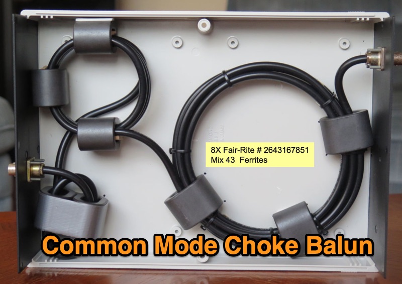 A common mode choke/balun, essential for mitigating common mode current on antenna feedlines, is detailed in this construction and measurement guide. It utilizes eight Fair-Rite #2643167851 Mix 43 ferrites housed within a Hammond 1598JSGYPBK plastic case, with RG-8X coax cable forming the windings. The document references design principles from Ian White, GM3SEK's article on cost-effective ferrite chokes. Specific construction details include the layout of three coils to minimize inter-coil coupling and methods for securing the ferrites with foam tape. The resource presents comprehensive measured data, including isolation impedance (magnitude, real, and imaginary components), Q factor, inductance, and phase angle across various frequencies. It also covers the choke/balun's coax frequency response and return loss characteristics. Techniques for measuring choking impedance are thoroughly explained, focusing on S21 transmission measurements with a Vector Network Analyzer (VNA) and testing ferrite beads in both S11 and S21 modes. The guide describes a practical setup using an aluminum sheet or baking foil for measurements and outlines the calculation of series impedance from attenuation in a 50-ohm system. Additionally, it details a method for determining the balun's equivalent L and C around resonance by adding a parallel capacitor.