Search results
Query: antenna project
Links: 563 | Categories: 26
Categories
- Antennas > 40M > 40 meter Delta Loop Antennas
- Antennas > 40M > 40 meter Yagi Antennas
- Antennas > 12M
- Antennas > 20M
- Antennas > 2M
- Technical Reference > Arduino
- Antennas > Bazooka
- Software > Circuit Design
- Antennas > Feed Lines
- Antennas > Horn
- Antennas > Log Periodic
- Technical Reference > LoRa and LoRaWan
- Antennas > Feed Lines > Open Wire
- Ham Radio > Personal Pages
- Operating Modes > QRP
- Antennas > Quadrifilar Helix
- Antennas > Receiving
- Antennas > Resonant Feedline Dipole
- Antennas > Satellite
- Antennas > Slim Jim
- Antennas > Spiral
- Technical Reference
- Antennas > Towers
- Antennas > Traps
- Antennas > Vertical
- Antennas > VHF UHF
-
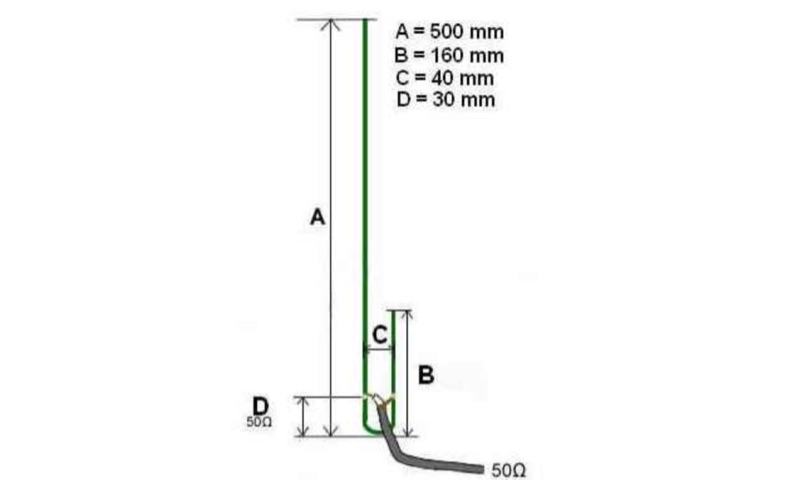
 This article describes the design and construction of a 4-meter band vertical sleeved dipole antenna, built to complement a newly acquired Yaesu FTDX10 transceiver. The simple yet effective antenna consists of modified coaxial cable housed in weather-resistant plastic conduit, featuring an integrated 8-turn choke coil. Despite common misidentification as an EFHW antenna, this design is actually a sleeved dipole that provides an excellent 50-ohm match across the band, achieving SWR values between 1:1 and 1.1:1. The project demonstrates an economical approach to entering the relatively quiet 4-meter band.
 -
 Explore a variety of ATV projects and resources for ham radio operators on ATV-Projects.com. Find helpful guides, tutorials, and tips to enhance your amateur radio experience. From antenna construction to equipment reviews, this site offers valuable information for hams looking to expand their knowledge and skills. Whether you're a beginner or seasoned operator, ATV Projects has something to offer for all levels of expertise.
 -
 Details the construction and performance of a phase-controlled receiving array, specifically a **MicroSWA** variant, optimized for QRP low band fox hunting on 40M and 80M. The resource documents the author's iterative design process, addressing significant regional noise challenges encountered during 0100-0230 UTC fox hunt periods. Initial experiments involved a director wire on a 40M vertical, yielding limited improvement, prompting a shift towards advanced null-steering techniques. The project leverages concepts from Victor Misek’s "The Beverage Antenna Handbook" and Dallas Lankford’s extensive work on phased receiving antennas for urban lots. A key modification involved integrating a new passive phase control box and a push-pull **Norton common base preamp** using 2N5109 transistors, designed for high third-order intercept performance to maintain weak signal integrity amidst strong adjacent signals. The system incorporates Faraday-shielded transformers with RG174 primaries on -75 ferrite cores, housed in ABS plastic pipe. Performance tests confirmed the MicroSWA's ability to produce deep, steerable nulls, achieving approximately 30 dB noise reduction on 160M, 80M, and 40M. This enabled detection of QRP signals undetectable on conventional transmit antennas. The final unit includes front panel controls, a 10-11 dB preamp, and a robust power conditioner, demonstrating effective noise mitigation for challenging low band QRP operations.
 -
 This project outlines a simple, cost-effective 40m band HF dipole antenna design, ideal for beginners. Constructed with insulated copper wire and a 1:1 balun, it offers a 50-ohm impedance, suitable for both 40m and 15m bands due to the harmonic relationship. Calculations account for a K factor, ensuring optimal length and performance. Antenna modeling with 4NEC2 confirms practical access to both bands, though real-world results may vary. Lightweight materials and straightforward assembly make it an accessible and versatile amateur radio solution.
 -
 145 MHz is the target frequency for this 2-meter Skeleton Slot Yagi Stack antenna project. The design focuses on feeding two stacked Yagi antennas using a skeleton slot radiator, which is a unique approach for VHF enthusiasts. The project details the construction process, including the loop tapered matching section for impedance matching, ensuring optimal performance. The use of specific components like the EH789 element holder and MB456 main mast bracket is highlighted, providing clarity on the assembly process. The construction utilizes 20x20 box aluminum bar for durability and precision. Key dimensions, such as the element length (ER-ED4) and main boom spacing (MM123), are meticulously outlined. This attention to detail aids in replicating the antenna design accurately. The downloadable PDF offers comprehensive instructions, making it accessible for amateur radio operators interested in VHF antenna construction. This project is particularly beneficial for those looking to optimize their 2-meter band operations. The inclusion of a skeleton slot radiator and loop tapered matching section demonstrates advanced techniques in antenna design, catering to both intermediate and advanced builders.
 -
 This project describes a high-performance EME antenna array consisting of two home-designed 9-element Yagis, each about 2.5 wavelengths long, combined into a 25-ohm system and matched to 100 ohms using 9/4λ sections of 50-ohm coax. The array supports rotatable polarity from 0° to 180°, allowing both horizontal and vertical polarization to optimize moonbounce performance under varying conditions. Despite operating for years without a balun—something another designer called “disastrousâ€â€”the system has delivered strong results, including copying very weak DX such as VK3KH at about -25 dB with only 120 W (around 2 kW ERP). The builder continues to refine the mechanics, having installed new gear motors and an upgraded follow-up control system in 2011.
 -
 Twenty 1-watt carbon film resistors are configured in parallel to construct a 50-ohm **dummy load** for amateur radio applications. The design incorporates a heatsink for thermal dissipation and an **SO-239 connector** for RF input, making it suitable for QRP operations. This budget-friendly project details component selection, soldering techniques, and mounting procedures, achieving a continuous power rating of 10 watts and intermittent handling of up to 100 watts across HF and VHF frequency ranges. The resource provides a step-by-step guide for assembly. This construction offers an economical solution for essential shack tasks such as antenna tuning, transmitter testing, and SWR meter calibration without radiating an RF signal. The utilization of readily available components significantly reduces the overall build cost compared to commercial alternatives, providing radio amateurs with a functional and reliable test accessory. While specific VSWR measurements are not provided, the design prioritizes practical utility for low-power transceiver diagnostics and general RF experimentation.
 -
 Python NEC2++ Module wraps the C++ API for antenna simulation of nec2++. It is easier to work with, and more powerful than the C-style API wrapper. Works with Python 2.7 and 3+.
 -
 This article describes a DIY RF field strength meter project inspired by VK3YE's "The Squeakie" design. The device, built around a 555 timer IC and a 1N4148 diode, converts RF signal strength into audible tones with proportional pitch. The author enhanced the original design by adding volume control, LED indication, and digital readout capabilities using an Arduino Nano and LCD display. The completed project functions as a versatile RF detection tool, suitable for antenna testing and fox hunting, while offering multiple output methods: audio, visual, and digital measurement display.
 -
 Demonstrates various technical projects and tutorials for amateur radio operators, focusing on digital modes, monitoring, and station setup. It covers topics such as implementing a _WSPR_ station, setting up ADS-B reception, configuring a _DXSpider_ cluster, and utilizing monitoring tools like Prometheus and Grafana. The resource provides practical guides for integrating modern IT solutions with ham radio activities, including Docker and Linux environments for radio applications. This site also features a publicly accessible online logbook, offering detailed statistics on QSOs by band, mode, and geographical zone, with visual mapping of contacts. It includes a comprehensive amateur radio lexicon, explaining hundreds of terms, and provides a real-time display of the F4HXN station's local weather conditions. The resource also aggregates information on upcoming ham radio events and offers a **SWR simulator** for antenna analysis, allowing users to visualize ROS changes based on frequency and antenna parameters.
 -
 The UHF J-Pole antenna described here utilizes an aluminum angle bar and 4mm galvanized threaded rod for its construction, with dimensions based on a previously published design. Assembly involves drilling the angle bar, securing threaded rod sections with nuts, and connecting the coaxial cable via cable lugs, ensuring the braid connects to the shorter element. ROS adjustment is achieved by manipulating nuts approximately **30mm** from the angle bar, allowing for fine-tuning of the impedance match. Once optimal tuning is established, _super glue_ is applied to seal the coaxial cable ends and protect the threaded rod cuts from corrosion, enhancing durability. This project emphasizes rapid realization with common hardware, providing a practical solution for radio amateurs seeking a simple yet effective antenna for the 70cm band.
 -
 The 4m Slim Jim antenna project provides a construction guide for a low-cost, high-performance aerial designed specifically for the 70 MHz FM band. This design achieves a 1:1 SWR across the 4m FM band with straightforward adjustment of the feed point, utilizing RG-58 coax. Its low angle of radiation contributes to effective signal propagation. Construction involves using plastic knitting needles as spreaders and a telescopic fishing pole for support, with components secured using two-part epoxy. Annealed bare single-core copper wire forms the radiating element. The setup process includes raising the antenna at least 3 meters above ground for tuning, adjusting the RG-58 feed point for optimal SWR, and then soldering connections. Waterproofing is achieved with yacht varnish. The design emphasizes low wind resistance for durability, making it suitable for exposed outdoor installations. A PDF construction diagram is available to supplement the written instructions.
 -
 The W6PQL 23cm Beacon Project describes a **1296 MHz** beacon designed for microwave propagation studies and equipment testing, capable of 30 watts output. It utilizes a PIC 16F628A microcontroller to generate CW and FSK keying for a crystal oscillator, followed by a series of frequency doublers and triplers to reach the target frequency. The final power amplification stage employs a Mitsubishi M57762 module, providing a robust 10-watt RF output. The design emphasizes stability and reliability for continuous operation, with the microcontroller code, written in assembly, provided for customization of the beacon's callsign and message. Originally located in CM97am and aimed at 140 true, the beacon used four 4-foot Yagis stacked vertically for a total ERP of 3kW. The article includes schematics, parts lists, and construction notes to guide builders, along with antenna pattern measurements. Although the beacon itself is no longer in service as of August 2010, the detailed documentation remains a valuable reference for amateur radio operators interested in building similar **microwave** projects or understanding beacon operation.