Search results
Query: 50 ohm
Links: 162 | Categories: 0
-
 The ZS6BKW wire antenna, a variant of the G5RV, utilizes a specific 13m (42.6 ft) length of 450-ohm window line as its matching section, feeding a 28.5m (93.5 ft) flat-top element. This design aims for lower SWR on 40m, 20m, 17m, 12m, and 10m compared to a standard G5RV, often achieving SWR values below 1.5:1 on these bands without an antenna tuner. The feedpoint impedance transformation provided by the window line allows for direct connection to 50-ohm coax on multiple bands. F4FHH's experience involved constructing the ZS6BKW and evaluating its performance against an _OCF dipole_ (Off-Center Fed) on various HF frequencies. The article includes observations on SWR readings and operational effectiveness, highlighting the ZS6BKW's suitability for multi-band operation. The antenna's overall length, including the flat-top and window line, is approximately **41.5 meters** (136 feet), making it a significant wire antenna for fixed station use. Comparative analysis with the OCF dipole provided practical insights into the ZS6BKW's advantages and limitations, particularly concerning bandwidth and tuner requirements.
 -
 This article describes the design of an antenna for local contacts on 7MHz, including a simple and efficient matching system that presents a 50 ohm load to the transceiver.
 -
 Demonstrates the construction of two distinct wideband RF preamplifiers, detailing their component requirements and performance characteristics. The first design leverages monolithic microwave integrated circuits (MMICs) such as the MAR-6, MAR-8, or PGA103, offering a broad frequency response from DC to 2 GHz with a gain of 22.5 dB at 100 MHz and a noise figure typically below 3 dB. This MMIC-based amplifier incorporates protection against power supply transients and features a 50 Ohm input/output impedance, operating from an 8-20 volt supply with low current drain. The second preamplifier design utilizes a BSX-20 transistor, providing amplification across the 14 MHz to 550 MHz range. This simpler, more economical build achieves an average gain of 12 dB at 145 MHz and a noise figure of approximately 1.1 dB. It operates from a 7-15 volt battery supply with a current draw of 6 mA. Both projects emphasize critical construction techniques, such as maintaining short RF connections, ensuring 50 Ohm impedance paths, and mounting the circuit within a shielded enclosure to optimize performance and minimize noise. The resource also discusses phantom power options for antenna-mounted preamplifiers and precautions for use with transceivers, including output protection diodes and static bleeders.
 -
 Operating a ZS6BKW antenna often involves understanding its lineage from the _G5RV_ design, with specific modifications by ZS6BKW to optimize performance on several bands. Through computational analysis and field measurements, the antenna's dimensions were refined to allow operation on 10, 12, 17, 20, and 40 meters without an antenna tuner. For 80, 30, and 15 meters, a tuner is necessary, though efficiency on 30 and 15 meters is noted as not particularly high. The physical configuration consists of two 13.755-meter radiating elements fed by a 12.20-meter section of 450-ohm ladder line. Tuning the antenna on the 20-meter band is critical, and any deviation in the ladder line's characteristic impedance necessitates recalculating the element lengths. The design is also referenced in the 12th edition of _Rothammel's Antennenbuch_, page 219. Proper common mode current suppression is crucial at the transition from ladder line to coaxial cable. This can be achieved with a common mode choke, such as several turns of coax wound into a coil or over a ferrite toroid like an Amidon T130. While a 1:1 balun is an option, it may introduce issues.
 -
 This simple 30m QRSS beacon is built entirely out of junkbox parts, the only component purchased specifically for this project was the 10,140kHz crystal. Hans Summers' 30m QRSS beacon project emphasizes simplicity and low cost, built almost entirely from reused parts. Key components include a 10,140kHz crystal, a 2N3904 transistor from a broken DVD player, and an ordinary LED used for frequency shift. The oscillator is stabilized in a polystyrene box, with power amplification driven by recycled copper PCB. Output power peaks at 360mW, and a custom 50-ohm dummy load manages heat. Though aesthetically unconventional, the beacon works effectively, fulfilling the project's low cost aim.
 -
 A _Topfkreis_ antenna, also known as a "bicycle pump" antenna, is presented as a simple vertical design for the 70 cm band. This variant of the J-pole antenna is notable for not requiring a ground plane, simplifying deployment. The construction details specify using aluminum tubing for the radiating element, with precise measurements for the quarter-wavelength outer tube (32 mm diameter) and the three-quarter wavelength inner sliding tubes (10 mm and 8 mm). Feeding is via a 50-ohm coaxial cable connected 90 mm from the base of the central tube. This design can achieve a gain of **4 to 6 dB** when properly tuned using the adjustable radiating element. The article details the fabrication of a critical aluminum washer, suggesting a method using a hole saw and a drill press as a lathe for precise adjustment. The illustrated example is specifically for the 70-centimeter band, and the author, Pop, clarifies construction points in the comments, including material choices and assembly techniques, ensuring a robust build for VHF/UHF operation.
 -
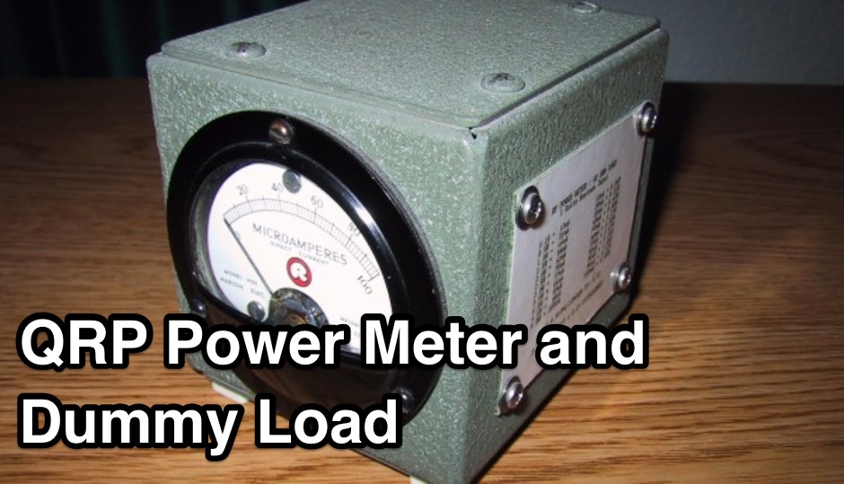 In this article the schematic is of AA5TB QRP power meter and dummy (50 Ohm) load combination
 -
 This resource details the conversion of an 80m elevated vertical antenna to include 160m operation, focusing on a relay-switched design over a trap-based approach. It presents specific feedpoint impedance values, such as **32 ohms** for 80m and **14 ohms** for 160m, and discusses the challenges of SWR drift encountered with the prior trap system during RTTY contesting. The article thoroughly explains the design choices for elevated radials, referencing _N6LF QEX data_ to debunk common myths regarding radial length and height, demonstrating that non-resonant radials can offer superior current uniformity. The construction section provides practical insights into building the vertical, including guying strategies, material selection from scrap pipe, and weatherproofing the relay assembly. It highlights the use of a common mode choke for the relay switching line, measuring approximately 5K ohms on both 160m and 80m, and details the L/C matching network's role in achieving a 50-ohm match at the end of a 300-foot RG-11 run. The author describes a precise VNA-based radial trimming procedure, achieving resonant values within a 3 KHz range. The content emphasizes the practical application of theoretical antenna principles, particularly concerning the interaction between the vertical element, cap hats, and the matching network. It offers a candid assessment of component selection, such as using junkbox parts and acknowledging the need for future upgrades to static drain resistors. The article serves as a comprehensive case study for advanced antenna builders tackling multi-band vertical designs.
 -
 Solves antenna matching problem with two phased antennas. Stacked rotary beams are popular. However, connecting two 50 Ohm antennas together presents some problems.
 -
 Presents a construction project for a linear-loaded 40-meter rotatable dipole, detailing the design evolution from mid-element coils to 300-ohm twinlead loading. It covers material selection, including repurposed fishing poles and EMT conduit, and outlines the assembly process for the antenna elements and mounting plate. The resource provides specific measurements for element lengths and linear loading sections, along with SWR plots demonstrating the antenna's resonance at 7.035 MHz with a 1.1:1 SWR, and bandwidth up to 7.120 MHz below 2:1 SWR. The article documents the antenna's performance during various RTTY and CW contests, including the SARTG RTTY and SCC RTTY contests in August 2006, and the ARRL DX CW and CQWW WPX RTTY contests in February 2007. It reports successful operation at 500-1000W, noting improved performance after replacing a faulty coax cable. Specific DX contacts from British Columbia, including stations in Europe and South Africa, are listed, illustrating the antenna's capability despite its shortened length and relatively low height of 55 feet. The content highlights practical considerations such as weatherproofing the connections and supporting the fiberglass elements to prevent sagging. It also includes a brief comparison to an inverted-V at similar height and a ground-mounted vertical, noting the rotatable dipole's quieter reception. The author shares insights into the iterative design process and tuning adjustments made to achieve optimal resonance.
 -
 A 10 meters band Slim Jim antenna project, made with a 450 Ohm slotted ribbon cable and secured on a 8 m fishing pole, by Steve G0KYA
 -
 An impedance transformer (9:1) to feed a high impedance long wire (~450 ohm), down to a 50 ohm unbalanced coaxial input.
 -
 The ZS6BKW antenna, a popular multiband wire antenna, offers improved band matching compared to the traditional G5RV. This construction guide details the process, beginning with specific dimensions: 13.11 meters (43 feet) for the 450-ohm ladder line and initial dipole arm lengths of approximately 14.8 meters each. It emphasizes the critical role of an _antenna analyzer_ for accurate tuning, particularly for determining the velocity factor of the ladder line and achieving a 1:1 impedance match. The article outlines the materials required, including a 1:1 current balun, 450-ohm window line, wire for the dipole arms, and a 50-ohm non-inductive resistor for testing. It provides a step-by-step procedure for cutting the ladder line to its electrical half-wavelength, explaining how to calculate the velocity factor using measured and free-space frequencies. For instance, a measured 50-ohm impedance at 12.54 MHz with a calculated free-space half-wavelength frequency of 11.44 MHz yields a velocity factor of 0.91. Final adjustments involve hoisting the antenna to its operational height and fine-tuning the dipole arm lengths to achieve optimal SWR, specifically targeting 14.200 MHz. The _ZS6BKW_ design is noted for its performance on 80m, 40m, 20m, 10m, and 6m, though it is not optimized for 15m operation. The author, _VK4MDX_, shares practical tips for durable construction using stainless steel wire and cable clamps.
 -
 Demonstrates the design and construction of a compact, portable multi-band mini-delta loop antenna, specifically optimized for /P (portable) operations from remote locations like Scottish islands. The resource covers the theoretical underpinnings of half-wave loops, contrasting closed and open configurations, and then details the application of a folded dipole principle to achieve a 50-ohm match for direct coax feed. It presents empirical formulas for calculating element lengths, considering the velocity factor of common wire types, and provides a detailed example for a 20m (14.175 MHz) version. The article includes a comprehensive table of dimensions and allowances for a five-band (20m, 17m, 15m, 12m, 10m) mini-delta beam, along with construction hints for the central support and balun. It specifies a 1:1 trifilar balun wound on a ferrite rod and describes the antenna adjustment process using an _MFJ-259B Antenna Analyser_. Initial test results indicate an SWR of 1:1 at resonance and a bandwidth of approximately 240 kHz on 20m, even at a low height of five feet above ground. The distinctive utility lies in its focus on a practical, easily deployable beam antenna for portable DXing, offering a viable alternative to more complex or larger arrays.
 -
 On this page is the design for Dual Band 2M / 70cm antenna with 3.2mm elements. The antenna has a 50 ohm designed driver. This Yagi has a unique element called a Open Sleeve
 -
 Demonstrates the design principles and performance characteristics of **corner reflector antennas**, emphasizing their high gain and directional properties. It covers critical design factors such as the corner angle and the spacing between the radiating dipole and the reflector vertex. The resource explains how reducing the corner angle increases gain but lowers feed impedance, making matching more challenging. Practical angles of 90 degrees or 60 degrees are discussed, with 90 degrees offering easier impedance matching despite slightly lower gain. Details key design considerations, including reflector side length exceeding two wavelengths and reflector width greater than one wavelength for a half-wave radiator. It specifies reflector construction using wire netting, sheet metal, or parallel metal spines spaced less than 0.1 wavelength. The article provides a table with general dimensions for UHF and VHF bands, noting typical impedance values of 50 to 75 ohms and expected SWR of 1.7:1 on the lower band edge. Adjustable radiator-to-vertex spacing is highlighted as crucial for final tuning.
 -
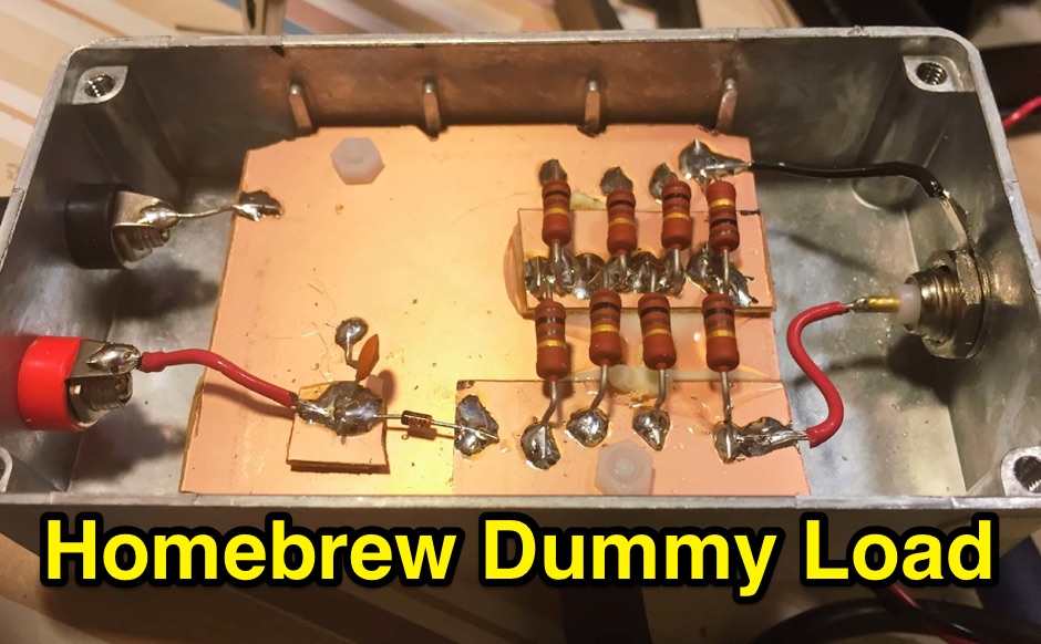
 A homebrew dummy load is usually a combination of several parallel carbon resistors, in order to be able a final resistance of 50 Ohms.
 -
 YF1AR multiband vertical antenna, based on orginal concept by VE7BS. Consist of 6 vertical elements and 6 base radials with a single 50 Ohm feed line.
 -
 This online guide details the microphone pinout for the Kenwood TR-7950 transceiver, specifically addressing the wiring configuration for a dynamic mobile microphone with a **500 Ohm** impedance. It provides a pin-by-pin breakdown for the 6-pin microphone connector, identifying the function of each active pin. The resource specifies that Pin #1 is for the microphone audio (white wire), Pin #2 controls the _PTT_ (black wire), Pin #3 activates the memory down function (blue wire), and Pin #4 controls the memory up function (red wire). Pin #6 is designated as the ground connection, while Pin #5 remains unused in this configuration. The document focuses on the physical wiring necessary to restore microphone functionality to the Kenwood TR-7950, a transceiver capable of **45 watts** output on the _2m band_. It directly addresses the technical challenge of re-establishing correct electrical connections after microphone wires have been disconnected from the connector. The information facilitates proper microphone operation for simplex QSOs and other voice communications. DXZone Focus: Online Guide | Microphone Pinout | Kenwood TR-7950 | PTT Wiring
 -
 If your doing any home brewing gear for ham radio its a great idea to have a dummy load. This will to your radio be the perfect antenna...it will never radiate but your radio sees a perfect 50 Ohm impedance.
 -
 A 50-ohm 10W resistor forms the core of this portable QRP antenna, designed by _K0EMT_ for convenient operation on 160m and 80m. The construction involves soldering the resistor to a BNC connector, with one lead to ground and the other to the center conductor, then insulating the assembly. This minimalist design aims to provide a highly portable solution for low-band QRP operations, acknowledging the inherent trade-offs between antenna size and efficiency. Testing with an antenna analyzer revealed low SWR on both 160m and 80m, with a Yaesu FT-817 confirming good matching. While 40m and 30m showed higher SWR, the primary focus remains on the lower bands. The author successfully tested the antenna with **2.5W CW** output, demonstrating its practical application for QRP field operations where ease of deployment is paramount, even if it means sacrificing some **gain** compared to full-sized antennas.
 -
 Construction details of a multiband dipole that can can operate at high power levels, and match its 50-ohm coax feedline without a tuner
 -
 CO2KK exposes some myths about using 75-ohm feedline with 50-ohm rigs and show how to build a cotanget transformer
 -
 One point eight MHz to 30 MHz is the operational bandwidth for this 4:1 Ruthroff voltage balun, designed to interface an unbalanced T-Match network with a balanced antenna system. The project details the construction using a _T200-2_ powdered iron toroid core, tightly wrapped in PVC electrical tape for insulation, and wound with 17 double bifilar turns of 1.25mm enamelled copper wire. This outboard balun offers flexibility, allowing hams to trial various baluns based on antenna system and impedance characteristics, rather than integrating it directly into the tuner. The resource includes a schematic of the balun, a wiring diagram showing winding connections, and a table suggesting alternative toroid cores like the T80-2 or T400-2 with corresponding winding counts. Component sourcing is straightforward, listing items such as the _Amidon_ T-200-2 core, SO-239 connector, and a sealed polycarbonate enclosure from Jaycar. Performance evaluation was conducted using an _AIM 4170C_ antenna analyser, demonstrating efficient 1:4 voltage transformation across the specified HF spectrum. Further efficiency tests involved measuring RF power loss at various frequencies, revealing minimal loss—less than 0.7 dB from 3.6 MHz to 30 MHz, and only 2.0 dB at 1.8 MHz. These measurements, performed under ideal 50-ohm conditions, confirm the balun's effectiveness as a low-loss interface for multi-band antenna systems. The page also links to several other balun and unun projects, including 1:1 current and voltage baluns, and 9:1 voltage ununs, providing a broader context for impedance matching solutions.
 -
 Optimizing the ZS6BKW antenna for full HF band coverage often requires specific modifications beyond its standard configuration. This resource details several enhancements, beginning with a simple series capacitor to improve 80m SWR, a technique W5DXP found effective for permanent installation due to its minimal impact on higher bands. Further improvements include a 10-inch parallel open stub for 10m resonance, shifting the frequency to 28.4 MHz with an SWR of approximately 1.8:1, a practical solution for Technician class operators. The document then explores a switchable matching section, adding or subtracting one foot of ladder line at the 1:1 choke-balun, which significantly impacts higher frequency bands and eliminates the need for a tuner on 17m. W5DXP's _AIM-4170D_ antenna analyzer measurements confirm these effects. More advanced modifications involve a parallel capacitor for further 80m SWR reduction, requiring remote switching for multi-band operation, and relay-switched parallel capacitors at specific points on the 450-ohm matching section to achieve low SWR on 60m, 30m, and 15m. These detailed steps, including _Smith chart_ analyses for the challenging bands, aim to transform the ZS6BKW into a truly all-HF-band antenna, reflecting W5DXP's practical experience in antenna tuning.
 -
 Presents a QRP AM/CW transmitter project specifically designed for the 10-meter band, utilizing a crystal oscillator and a collector-modulated AM oscillator. The design employs a 2N2219(A) transistor in a Colpitts configuration, generating 100 to 350 mW of RF output power depending on the 9-18 Volt supply voltage and modulation depth. Frequency stability is maintained by a 28 MHz crystal, with fine-tuning possible via a Ct1 trimmer capacitor for approximately 1 kHz adjustment. The resource details the RF oscillator stage, implemented with a 2N2219 NPN transistor, emphasizing frequency stability and low power dissipation. It also covers the amplitude modulation stage, managed by a 2N2905 PNP transistor, which impresses audio information onto the carrier. Selective components (C3, C4, C7, C5) enhance voice frequencies within a +/- 5 kHz bandwidth, and modulation depth is controlled by R2 and R3. The project includes a 3-element L-type narrow bandpass filter (Ct3, L3, C10) to suppress harmonics and ensure a clean output signal. The project provides a complete schematic diagram, a comprehensive parts list including specific capacitor, resistor, and inductor values, and construction notes for the coils (L1, L2, L3). It also offers practical advice on enclosure requirements, suggesting an all-metal case or a PVC box with graphite paint for RF shielding. Operational parameters such as current draw (27mA@9V to 45mA@16V) and input impedance (50 Ohms) are specified, alongside guidance on antenna matching and the importance of a valid amateur radio license for 10-meter band operation.
 -
 A fractional bandwidth of up to 30:1 characterizes spiral antennas, making them highly effective across a very wide frequency range, often from 1 GHz to 30 GHz. The resource details two primary types: the **Log-Periodic Spiral Antenna** and the **Archimedean Spiral Antenna**, defining each with specific polar functions and illustrating their planar configurations. It explains that spiral antennas are typically circularly polarized, with a Half-Power Beamwidth (HPBW) of approximately 70-90 degrees, and a peak radiation direction perpendicular to the spiral plane. The content elaborates on critical design parameters affecting radiation, including the total length (outer radius) for lowest frequency, the flare rate ('a' constant) for optimal radiation versus capacitive behavior, the feed structure (often an infinite balun) for high-frequency operation, and the number of turns (typically 1.5 to 3 turns). It also discusses the theoretical impedance of 188 Ohms for Log-Periodic spirals, derived from Babinet's Principle, noting actual impedances are often 100-150 Ohms. The article presents a simple construction method for an Archimedean spiral, demonstrating VSWR and efficiency measurements. Measurements from a constructed spiral antenna show a VSWR that is fairly constant across the band, albeit with a mismatch loss of about 3 dB. The antenna efficiency remains around -5 dB (31.6%) across its operating range, indicating a decent wideband radiator despite opportunities for optimization.
 -
 This is a simple portable 2-meter J-Pole antenna. You start with a piece of 450-Ohm Ladder Line
 -
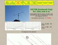 This Duoband-Yagi has a boom of 3.60 m and 3 elements for 10 m 4 elements for 6 m and one feedpoint with 50 Ohm
 -
 A home made dipole antenna for 10m, 6m, 4m bands made with two sections of 450 and 300 Ohm ladder lines, cut to achieve acceptable SWRs on all bands
 -
 A 50-ohm generator feeding a 50-ohm line connected to a _quarter-wave transformer_ (150 ohms) terminated in a 450-ohm load is analyzed to understand transient behavior. The paper meticulously tracks voltage and current waves, reflection coefficients, and power levels through a sequence of events, starting from quiescent conditions. It details how incident and reflected waves combine and interact at impedance discontinuities, illustrating the dynamic changes in impedance and SWR at various points in the system. The analysis reveals that the impedance at the interface between the 50-ohm line and the 150-ohm transformer changes from 150 ohms to **64.3 ohms** after the first reflected wave arrives. Subsequent reflections cause the impedance to asymptotically approach 50 ohms, reaching **53.22 ohms** after five wave terms. The study also examines the generator's reaction to transient SWR changes, noting that a 3:1 SWR can temporarily reduce generator output to 0.75 watts, but these effects are temporary and diminish as the system approaches steady-state conditions.
 -
 The X80 multi-band HF vertical antenna, a commercial iteration of the Rybakov design, exhibits a physical length of 5.5 meters, or approximately 18 feet, and is constructed from aluminum tubing. It operates as a non-resonant vertical, requiring an external antenna tuner for impedance matching across its intended operating frequencies. The antenna's design incorporates a 1:4 UNUN at its base, facilitating a nominal 50-ohm feed point impedance for the coaxial cable. Performance observations indicate effective operation on 40 meters, 20 meters, 15 meters, and 10 meters, with reduced efficiency on 80 meters and 160 meters due to its relatively short electrical length for these lower bands. Comparative analysis with a G5RV dipole and a half-wave end-fed antenna reveals the X80 offers a lower take-off angle, beneficial for DX contacts, particularly on the higher HF bands. Field tests conducted with an Icom IC-706MKIIG transceiver and an LDG AT-100ProII autotuner demonstrate the X80's ability to achieve acceptable SWR across 80m through 10m. The antenna's compact footprint and ease of deployment make it suitable for restricted spaces or portable operations, though its performance on 80 meters is noted as a compromise compared to full-size resonant antennas.
 -
 A simple 50 ohm dummy load to test transmitters. includes a simple RF diode detector to measure the peak voltage, and calculate the power
 -
 C-Poles for 20m and 6m, it is a folded half-wave dipole with an asymmetrical tapped 50-Ohm-point in the lower part of the antenna. Design hints by DK7ZB
 -
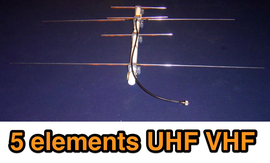
 A 5 element yagi beam antenna for ten meters band with full dimentsions, eznec file and coax match informations for 50 ohms feed line
 -
 Benelec Pty Ltd specializes in the design and manufacturing of **antennas** and RF components, covering a broad frequency range from 0.002 GHz to 8 GHz. Their product line includes Land Mobile Radio Antennas, such as HF 2-30MHz, VHF 40-180MHz, and UHF 200-520MHz models, alongside specialized Military Antennas for dismounted, UxS, C2, and EW applications. The company also produces Cellular Antennas, including 4G/5G and GPS/GNSS types, and Marine Antennas for both vessel-mounted and fixed-site installations. Additionally, Benelec offers a comprehensive range of coaxial cables, connectors like N-Type and SMA, and various radio accessories. The company's offerings extend to RF components such as duplexers, diplexers, and 50 Ohm loads, as well as DAS components like directional couplers and hybrid combiners. Benelec provides EMP and lightning protection solutions, including 1/4 Wave Stub protectors and replaceable GAS capsules. Their product catalog also features P25, DMR, and FM Analog radios, along with portable and mobile radio accessories like batteries, chargers, and cabled headsets. The company supports various sectors with robust communication solutions.
 -
 Designing and constructing portable wire antennas for HF operations, this resource explores several configurations including the _foldback dipole_ for space-constrained setups and an inductively shortened dual-band dipole for 20m and 40m. It details the calculation of inductance for shortened elements, providing a Visual Basic 6.0 program screenshot that illustrates determining coil parameters like turns and length for a **25.5 uH** inductor. The document emphasizes practical considerations such as adjusting wire lengths for optimal SWR, noting that a dual-band dipole achieved SWR below 2:1 on both 20m and 40m, with careful adjustment bringing it under 1.5:1. Further, the resource describes a half-wave antenna matched with a coaxial stub, a method often referred to as the _Fuchskreis_ in German amateur radio circles, to transform the high feedpoint impedance to 50 Ohms. This monoband solution, for a 20m application, uses a stub length of **2.98m** (0.216 lambda multiplied by coax velocity factor) and a shorted stub of approximately 48cm. The coaxial stub design is highlighted for its resilience to ground proximity, allowing it to be rolled up or laid on the ground with minimal SWR impact, making it highly suitable for portable QRP operations.
 -
 Antenna tuners are crucial for matching the impedance of antennas to the 50 ohm output impedance of transmitters. The _LDG Z-11 Pro_ is an automatic antenna tuner designed to handle up to 125 watts, making it suitable for a wide range of amateur radio applications. Its compact form factor allows it to pair well with transceivers like the _FT-857D_, providing a portable solution for operators who frequently change locations or setups. The tuner covers the 80 through 6 meter bands, offering a broad impedance match capability. Although it struggles with some loads, it performs well with typical ham antennas, even managing to load an 80 meter dipole on 6 meters. One of the standout features of the _Z-11 Pro_ is its 8000 memory slots, which enable it to remember successful matches and quickly retune when revisiting frequencies. This memory function significantly reduces tuning time, often to less than half a second. The unit is well-constructed, with improved pushbuttons and a sturdy metal case that offers good shielding. However, users should be aware of potential RFI issues and the lack of a power switch, which requires disconnecting the power cord to turn off the unit completely. Overall, the _LDG Z-11 Pro_ is a user-friendly and cost-effective tuner, offering advanced features that enhance its utility in various amateur radio setups.
 -
 This antenna article is geared towards new Hams and antenna builders looking for a very inexpensive 6 band antenna that can be efficiently fed with 50 ohm coax without a tune
 -
 The **136kHz Vertical Antenna** at G3YMC employs a Butternut HF2V structure, standing 10m tall. It integrates a 6.5mH loading coil to achieve resonance, with a matching transformer for impedance adjustment. The antenna's configuration includes top loading via a 12m horizontal wire, enhancing capacitive impedance. Initial measurements indicated a high impedance of around 300 ohms, necessitating a transformer for a 50-ohm match. Despite challenges with ground losses, the vertical antenna has shown improved performance in specific directions, filling nulls present in the previous loop antenna setup. The tuning remains broad, with variations due to environmental factors affecting the matching. Ongoing adjustments and comparisons with the loop antenna will continue to refine its effectiveness.
 -
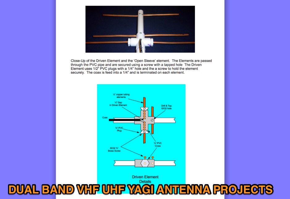 On this page are designs for Dual Band 2M / 70cm antennas. All antennas are 50 ohm designed driver. These Yagis have a unique element called a Open Sleeve. 4 Element 5 element and 9 element Dual Band - 2M / 70cm antenna projects
 -
 The configuration of this antenna is a triangle with apex in the top of a very tall tree. The antenna is fed at a bottom corner using 450 ohm ladder line.
 -
-
 The resource provides coaxial cable attenuation data, listing signal loss in dB per 100 feet for various cable types across a frequency range from 1 MHz to 5.8 GHz. The initial table details attenuation for cables such as _RG-58_, _RG-8X_, and RG-213, with impedance values of 50 ohm or 75 ohm, at frequencies up to 1 GHz. For example, _RG-58_ exhibits **0.4 dB** loss at 1 MHz and **21.5 dB** loss at 1 GHz per 100 feet. A subsequent table expands on this data, including LMR series cables like _LMR-400_ and LMR-600, along with other types such as 9913F7 and RG214. This section covers frequencies from 30 MHz to 1,500 MHz, also noting the outer diameter of each cable. For instance, _LMR-400_ (0.405" diameter) shows **0.7 dB** loss at 30 MHz and 5.1 dB loss at 1,500 MHz per 100 feet. The final section focuses on VHF/UHF/Microwave amateur and ISM bands, presenting attenuation in dB per 100 feet (and meters) for frequencies including 144 MHz, 450 MHz, and 2.4 GHz. This table includes larger diameter hardline options like 1/2" LDF and 7/8" LDF, in addition to flexible coaxial cables. For example, 1/2" LDF cable demonstrates **0.85 dB** loss at 144 MHz and 6.6 dB loss at 2.4 GHz per 100 feet. DXZone Focus: Coaxial cable attenuation | LMR-400 | RG-58 | 5.8 GHz
 -
 T2FD is a 600-900 ohms folded dipole, terminated with resistor. Feed impedance is coupled with 50/600 ohms voltage balun. It is a wide band antenna with rather low SWR over the full designed frequency range: antenna tuner is seldom needed.
 -
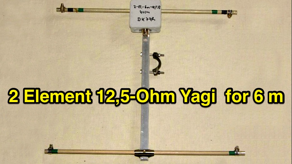 2-Element-12,5-Ohm-Yagi with 0,40m-Boom complete description of all details for building this Yagi and stacking to an array
 -
 The dbm online calculator and reference table for 50 Ohm
 -
 Moxon is a rectangle shaped directional antenna, originally designed by Les Moxon G6XN. There are couple of advantages of using this antenna. It is small in size, Easy to mast, Balanced to 50 Ohms, Near 1:1 SWR, Excellent Front to Back (F/B) ratio, Large bandwidth
 -
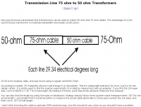
 The article, "Using 75 Ohm CATV Coaxial Cable," details methods for employing readily available 75-ohm CATV hardline in standard 50-ohm amateur radio setups. It addresses the inherent impedance mismatch and practical considerations, such as connector compatibility, for hams seeking cost-effective, low-loss feedline solutions. The resource specifically contrasts common 50-ohm cables like RG-8, RG213, and _LMR-400_ with 75-ohm hardline, highlighting the latter's lower loss characteristics, particularly at VHF and UHF frequencies. It explores two primary approaches to manage the impedance difference: direct connection with an acceptable SWR compromise and precise impedance transformation. The direct connection method acknowledges that a perfect 1:1 SWR is not always critical, especially when using low-loss coax. For impedance transformation, the article explains the use of half-wavelength sections of coax to reflect the antenna's 50-ohm impedance back to the transmitter, noting its single-frequency effectiveness. It also briefly mentions transformer designs using toroid cores and a technique involving two 1/12 wavelength sections of feedline for broader bandwidth. The content further clarifies the concept of _velocity factor_ for calculating electrical versus physical cable lengths, providing a generic formula for precise length determination. It notes that while half-wave matching is practical for 10 meters and above, it can result in excessively long runs for lower bands like 160 meters, potentially adding **250 feet** of cable. The article also mentions achieving a usable bandwidth of 28.000 MHz up to at least **28.8 MHz** on 10 meters with specific transformation techniques.
 -
 A page describing how to home made a custom 9:1 balun for a common portable wire antenna. The author suggest to use 4C65 or FT140-61 toroids instead of the common Amidon T200-2