Search results
Query: qst
Links: 120 | Categories: 0
-

-
 K8CU builds a classic 1967 QST semiconductor project during the 40th anniversary year of the original project publication.
 -
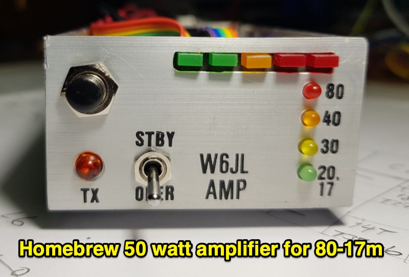 The resource details the construction of a homebrew 50-watt FET amplifier, based on Don W6JL's _QST Homebrew contest_-winning design from 2009. It functions as an afterburner for QRP transceivers, providing a **12dB** power lift. The amplifier utilizes IRFZ24N FETs and covers the 80, 40, 30, and 20-meter bands, with the 20m LPF extending to 17m. Key technical aspects include an FT37-43 transformer for the input network, a relay-switched 3dB pad for lower bands controlled by an _Arduino Nano_, and an RF-actuated T/R switch. The LPF board integrates four relay-switched filters rated for 50 watts, using capacitors with a minimum 250VDC rating. Performance measurements indicate a power gain ranging from **4.4dB** on 20m to 8.1dB on 80m, with a required drive power of approximately 5 watts. The article also discusses thermal management, current limiting considerations, and component sourcing.
 -
 QST Magazine said, We have the hardest T-Hunts in the Country
 -
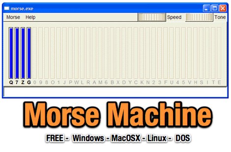 Learn morse code with morse machine, A Fully Automatic Morse Code Teaching Machine first described in a May 1977 QST. Free for Windows MacOS Linux and DOS
 -
 QST Article on what you should know about matching networks for class C RF power amplifiers
 -
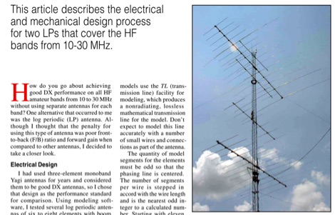 This QST article describes the electrical and mechanical design process for two LPs that cover the HF bands from 10-30 MHz
 -
 Understanding Amateur Radio NVIS Antennas and Propagation, derived from The ARRL Antenna Book and QST Articles
 -
 Sometimes we need a little more output filtering than traditional designs offer. Look at a new filter that can give you that extra boost. QST article by W3NQN
 -
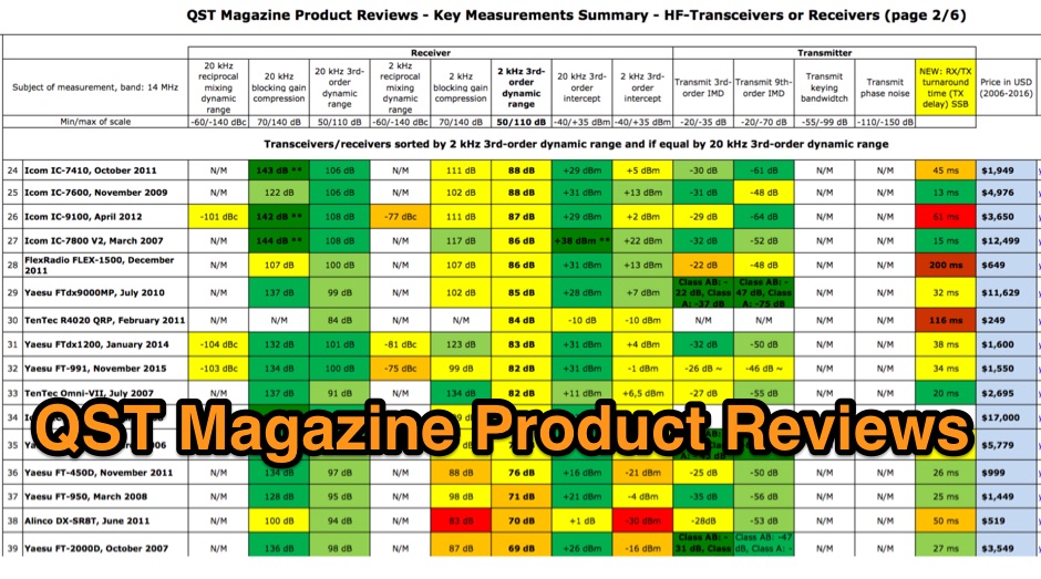 QST Magazine Product Reviews - Key Measurements Summary - HF-Transceivers or Receiver and Linear Amplifiers
 -
 Slot cubes are folded skeleton slot antennas with widened, folded dipoles bent into a cube to reduce size. QST Article 12 2019
 -
 Ten essential tips and truisms for understanding HF antenna: Non-resonant wire dipole antennas fed with open-wire line and an antenna tuner can function effectively as multiband antennas, as detailed in "The Classic Multiband Dipole Antenna" by WB8IMY in March 2004 QST. Coaxial cable, unlike balanced parallel-wire feed lines, can cause RF to travel on the outer shield braid, leading to RF feedback to the station; a 1:1 balun at the dipole center can mitigate this by isolating the unbalanced coaxial feed line. Antenna gain is achieved by shaping and directing RF energy, with beam antennas concentrating power in a specific direction, and wire antennas also exhibiting shaped radiation patterns. An antenna tuner's primary role is to match the transceiver's 50-ohm output to the antenna system's impedance, allowing modern transceivers to deliver full power. Wire antennas do not always require center feeding; end-fed long wires or off-center-fed dipoles (like the Windom) can be used, though they often necessitate an antenna tuner and a counterpoise or radial network. Dipole antennas do not need to be perfectly horizontal; their legs can be bent or inclined, which affects feed point impedance and may require SWR experimentation with coaxial feed. Vertical antennas shorter than a half wavelength require an efficient ground system, typically comprising elevated or buried radial wires, with more radials generally leading to better efficiency. A 1:1 SWR indicates an impedance match but does not guarantee antenna efficiency; an inefficient vertical antenna with a poor ground system can show a low SWR while wasting most RF as heat. Investing in high-quality, low-loss feed line, especially coaxial cable, is crucial for maximizing RF signal transfer and overall antenna system performance.
 -
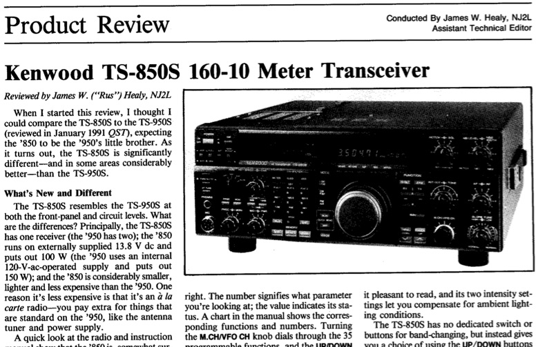 QST Magazine, 1991 July, review of the Kenwood TS-850S 160-10 Meter Transceiver
 -
 Notes on using the QST propagation charts to determine propagation conditions
 -
 The Tuna Tin 2 is a simple transmitter originally designed by the legendary author and experimenter Doug DeMaw, W1FB. The TT2 was first published in the May 1976 issue of QST.
 -

-
 WR1B review of the Kenwood TS-570D on QST Jan 1997
 -
 Technical Correspondence, QST, July 1990 - Why even "perfect" phased array element currents don't produce perfect patterns.
 -
 Balanced feed with coaxial line by John F. Clemens W9ERN
 -

-
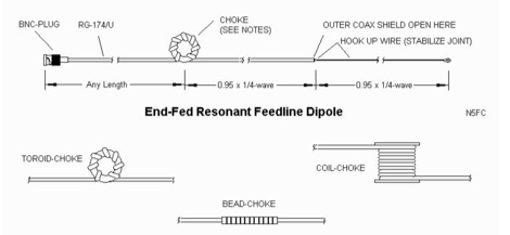 Experiences with the end-fed dipole based on the concepts presented by J. Taylor in an article titled RFD-1 and RFD-2: Resonant Feed-Line Dipoles in QST. August 1991.
 -
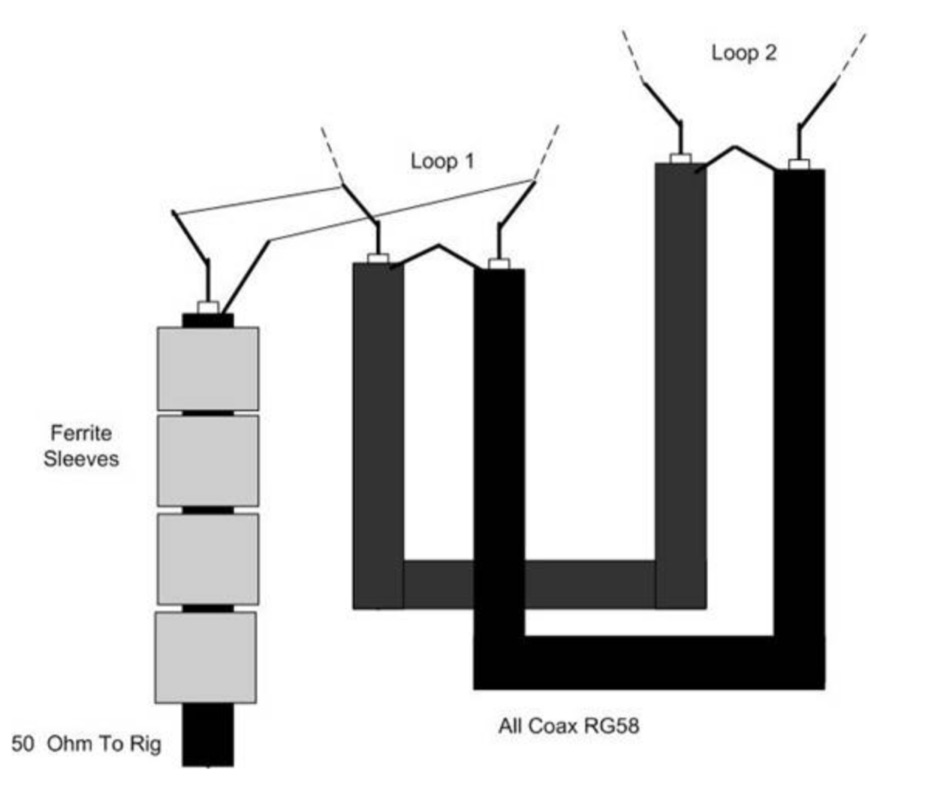 Simple 6 Metre DX Antenna based on an article by LB Cebick in QST May 2002 on a Quad Turnstile antenna. This antenna is basically two full wave loops mounted at right angles fed 90 degrees out of phase to produce an omni-directional horizontally polarized pattern
 -
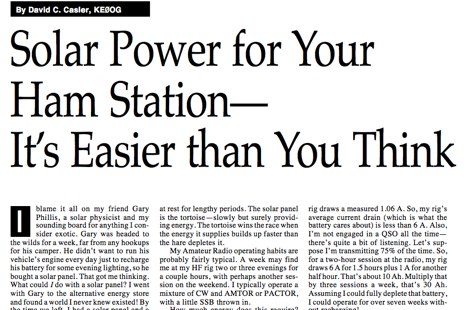 Solar Power for Your Ham Station, It is Easier Than You Think QST article April 96 by KE0OG via Repeater-Builider.com
 -
 This resource details the construction of a Moxon rectangle antenna, a two-element wire beam, drawing inspiration from a _QST_ article by Allen Baker, KG4JJH, and a project group led by KD6WD. It outlines the use of _AC6LA_ software for critical measurements (A-E) to design the antenna for specific bands like 17 meters, emphasizing the simplicity of adjusting frequency and wire size. The guide covers material selection for spreaders, such as telescoping fiberglass fishing poles, and various hub constructions, including aluminum tubing and PVC joints, with accompanying images. The author shares practical insights from building multiple Moxons for 10, 15, 17, and 20 meters, noting consistent 1:1 SWR at design frequencies and broadbanded performance. It describes the feedpoint assembly using a 1:1 Yagi current balun and wire nuts for robust, adjustable connections. The resource also discusses element insulators made from Lucite strips and attachment methods to spreaders using plastic wire ties and duct tape, ensuring precise element spacing. Performance observations include significant signal improvements (4-5 S units) over quad loops and a unique "DX-Vane" effect where the suspended antenna self-aligns with the strongest DX signal. The author also recounts an unsuccessful attempt at a dual-band 17/20 meter Moxon, concluding that the Moxon is inherently a monoband antenna, supported by _EZNEC_ plots for a 17-meter design.
 -
 October 2003 QST article on working digital mondes with sound card interfaces
 -
 This is a QST Article published in January 1982 by W1FB D. Demaw and HH Beverage and is a complete review of the original article published in 1922, which updates and reivew the beverage antenna theory and developlment, explaining the antenna design of transformers and gives accurate reports on antenna general performance.
 -
 VHF UHF Microwave EME Standings, a Who's Who on top in USA
 -
 A look behind the scenes, learn how the ARRL laboratory evaluates new products, and what all those numbers mean to you by WA1SVF
 -
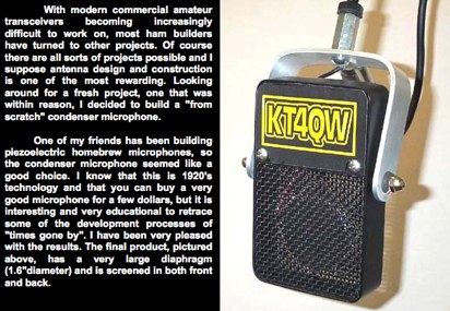 A december 2003 QST article to Build a condenser microphone that will perform like the costly commercial units by KT4QW
 -
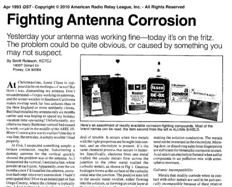 How to make proper maintenance of your antenna. Fighting Antenna Corrosion is a QST article published in 1993 that helps on antenna maintenance works
 -
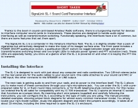 Designed to handle audio signal interfacing as well as transmit/receive switching Reviewed by Steve Ford, WB8IM
 -
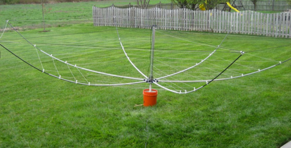 This version of the broadband hexbeam is based on the work of Hunt G3TXQ, HB9MCZ, and Shoemaker K4KIO. EZNEC model is based on a wider element spacing than the version published in QST by K4KIO
 -
 Exploring these mysterious transmissions and how their strong following has created a niche in the community. Free article in PDF Format from QST November 2019
 -
 Kenwood TS-590S QST review comments and table comparison vs Elecraft K3
 -
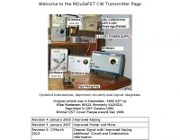 Original article was in December, 1986 QST
 -
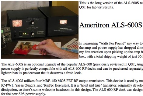 ALS-600S review, an abbreviated version of this review first appeared in the March 2005 issue of QST. See QST for lab test results.
 -
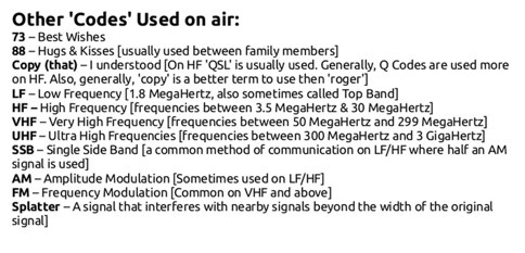 Taken from April 1935 issue of QST page 60 where there is a short article on the origin of 73
 -
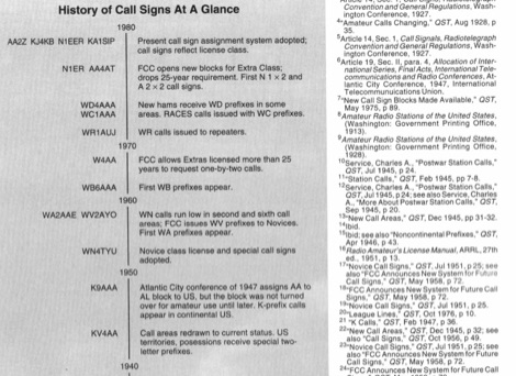 QST article from May 1994 about history of call signs from the very beginning to present system. Article explains call sign allocations, call areas, prefixes for novices and prefixes like K WA WB WD, callsigns during and after the world war II and other curiosities on US Call signs.
 -
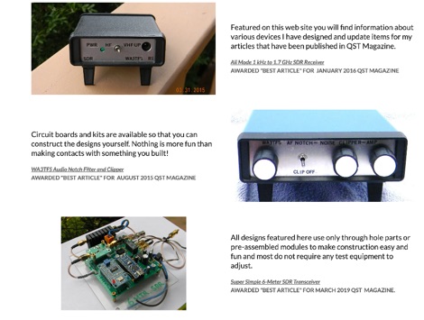 Details on projects by WA3TFS published in QST magazine over the past few years. Includes an online shop with several ham radio kits, circuit boards, simple SDR transceivers
 -
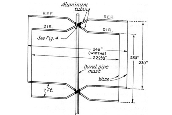 Rotatable Antenna with Phased Elements based on the orignal design concept of HB9CV antennas, is considered to have an higher gain than standard quad antennas. The Swiss Quad Antenna does not need any spreader or boom.
 -
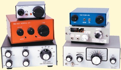 Review of 6 QRP CW transceivers by AE5X published in QST December 2000
 -
 LA3ZA on magnetospheric ducting as an explanation for delayed signals on 3.5 MHz
 -
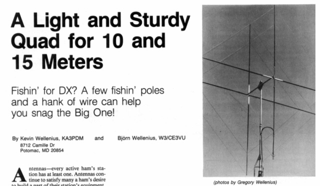 A light and sturdy Quad for 10 and 15 meters. Basic Quad antenna design considerations. Building and assembling a dual band HF QUAD antenna, designing and joining cross-arms and boom, assembling spreader and element wire installation notes. QST article.
 -
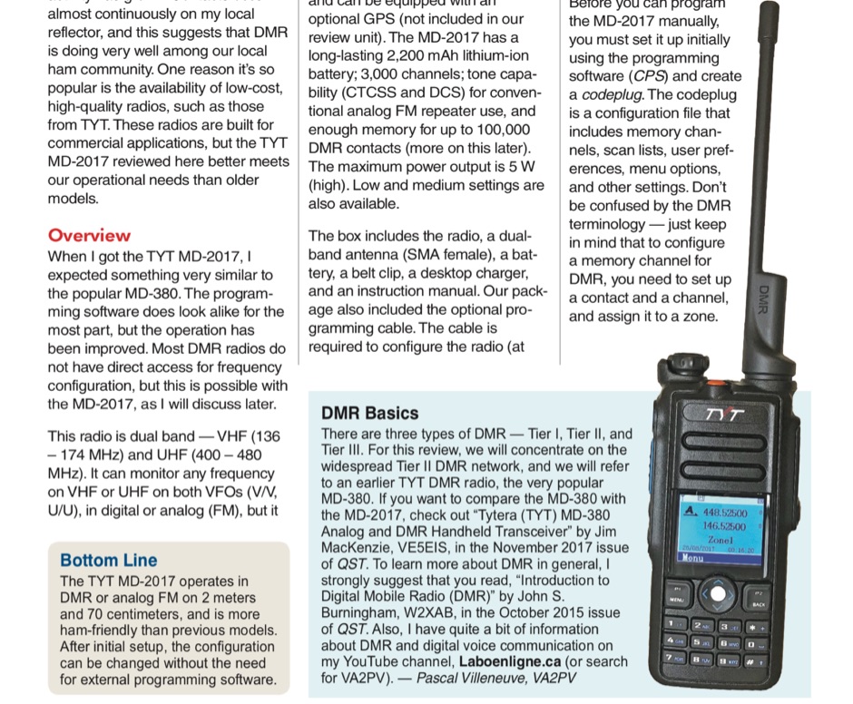 TYT MD-2017 Dual-Band Analog and DMR Handheld Transceiver Reviewed by Pascal Villeneuve, VA2PV
 -
 WSJT New Software for VHF Meteor-Scatter Communication QST Article December 2001 by K1JT
 -
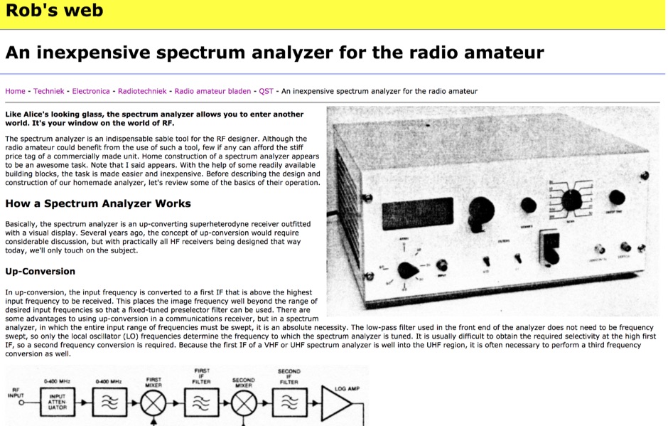 An inexpensive spectrum analyzer for the radio amateur, with a respectable performance and a quite good dynamic range. Schematic and basic information on how spectrum analyzers works.
 -
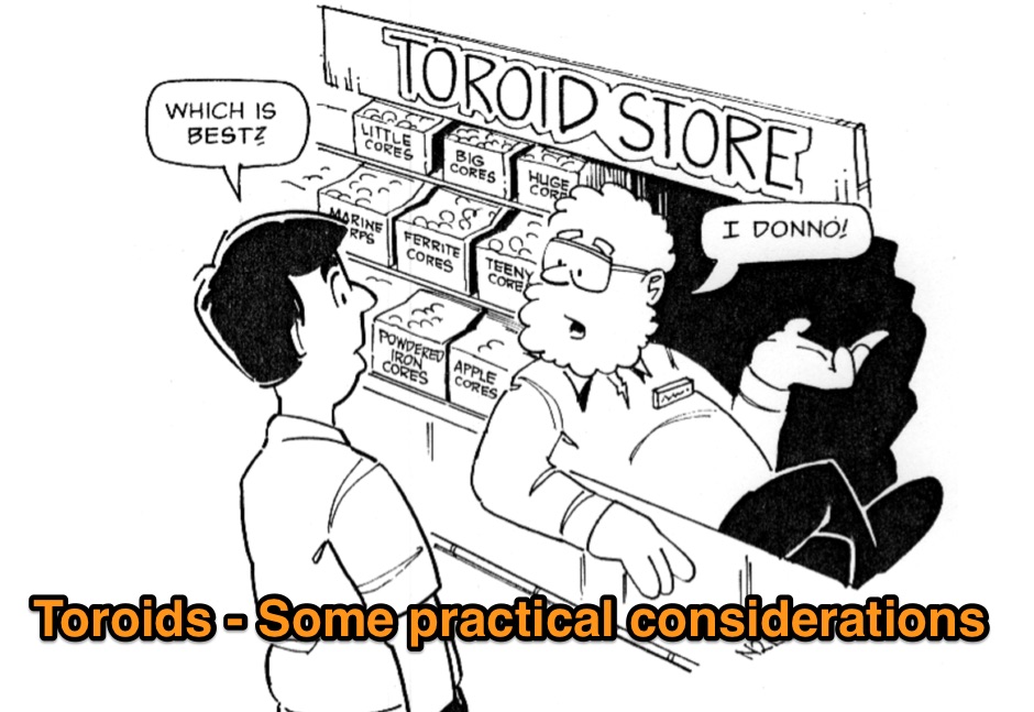 Are you confused when it comes to using toroids? The tips given in this article may simplify your next project. Comprehensive article about choosing the proper toroid.
 -
 A little gadget was found in an article in QST, made with 1 pair of powerpole connectors a resistor and two leds
 -
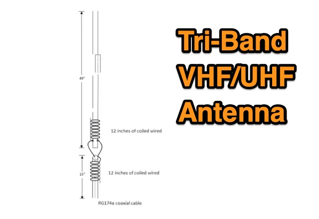 The TBJ-1 – a triband base antenna was published in March 2017 QST. This antenna covers 2M/220 MHz/70cm in one 6ft 3/4 inch PVC pipe and requires no radials.
 -
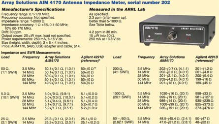 Array Solutions AIM 4170 Antenna Impedance Meter, QST Review