Search results
Query: 40 80 m antenna
Links: 173 | Categories: 3
-
 The ZS6BKW multi-band antenna, an optimized variant of the classic G5RV, is presented with detailed construction and tuning instructions. This resource outlines the antenna's design principles, which were developed by _Brian Austin (G0GSF)_ using computer programs and Smith charts to achieve optimal dimensions. It provides specific guidance on calculating and adjusting the lengths of the radiators (L1) and the matching ladder line (L2), emphasizing the critical role of velocity factor (VF) in achieving resonance. The article includes a step-by-step procedure for empirically determining the VF of ladder line using an antenna analyzer, ensuring accurate physical lengths for the matching section. It details the tuning process for the radiators, offering practical tips for incremental adjustments to achieve the best SWR curve. The resource presents SWR measurement results obtained with an _AIM-4170C_ analyzer across multiple bands, alongside predicted SWR graphs from an AutoEZ model. It confirms successful contacts on 80, 40, 20, and 17 meters, including a **17-meter DX contact** to Italy. EZNEC and AutoEZ models for the ZS6BKW antenna, covering 80 through 6 meters, are provided for download, allowing further analysis and customization. The document specifies component details, such as the use of Wireman 554 ladder line and #14 AWG THHN copper wire, and discusses the antenna's performance characteristics, noting high SWR on 15 and 30 meters but successful tuning on 6 and 80 meters with an external tuner.
 -
 Demonstrates the operational status and reception reports for the SK6RUD/SA6RR QRPP beacons, which transmit on 478.9 kHz, 1995 kHz, 10.131 MHz, and 40.673 MHz. These beacons utilize extremely low power, with the 630-meter beacon operating at approximately 0.1 watt ERP into an L-antenna, showcasing the potential for long-distance contacts under favorable propagation conditions. The site details the specific frequencies and antenna types employed, such as a vertical at 500 kHz and a 1/4 vertical for higher bands. The resource compiles over 10,530 reception reports from amateur radio operators worldwide, logging details such as date, time, band, RST signal report, locator, distance, and receiver setup. Notable long-distance reports include a 500 kHz reception by AA1A-Dave from 5832 km in 2008 and a 10.133 MHz reception by ZL2FT-Jason from 17680 km in 2010, illustrating the global reach of these low-power transmissions. Each log entry provides specific equipment used by the reporting station, including transceivers like the Yaesu FT817, ICOM IC-7300, and various antenna configurations such as coaxial mag loops, inverted Ls, and end-fed wires. The primary objective of the SK6RUD beacons is to challenge conventional notions of power requirements for effective two-way communication, proving that contacts over significant distances are achievable with minimal output. The site also includes a submission form for new reception reports, fostering community engagement and continuous data collection on propagation phenomena across different bands. The detailed logs offer practical insights into real-world propagation characteristics and the efficacy of QRPP operations.
 -
 A presentation of a HF multi-band sloper antenna. This antenna project is for low band operations, and antenna presented in this article works on 40 80 and 160 meters band. Article is in Polish.
 -
 In this experiment the autor is going to explore the use of a 1:64 matching network on the End Fed Long Wire Antenna. Experiment will consist in build a 80-40-20-15-10 meter End Fed Long Wire Antenna with a 1:64 matching network from the documentation available on the internet
 -
 Benelec Pty Ltd specializes in the design and manufacturing of **antennas** and RF components, covering a broad frequency range from 0.002 GHz to 8 GHz. Their product line includes Land Mobile Radio Antennas, such as HF 2-30MHz, VHF 40-180MHz, and UHF 200-520MHz models, alongside specialized Military Antennas for dismounted, UxS, C2, and EW applications. The company also produces Cellular Antennas, including 4G/5G and GPS/GNSS types, and Marine Antennas for both vessel-mounted and fixed-site installations. Additionally, Benelec offers a comprehensive range of coaxial cables, connectors like N-Type and SMA, and various radio accessories. The company's offerings extend to RF components such as duplexers, diplexers, and 50 Ohm loads, as well as DAS components like directional couplers and hybrid combiners. Benelec provides EMP and lightning protection solutions, including 1/4 Wave Stub protectors and replaceable GAS capsules. Their product catalog also features P25, DMR, and FM Analog radios, along with portable and mobile radio accessories like batteries, chargers, and cabled headsets. The company supports various sectors with robust communication solutions.
 -
 The AB2RA bowtie 80 meter antenna includes also a 40 meter dipole
 -
 Building a Windom HF Antenna. A PDF file presentation about homebrewing a windom antenna for the HF bands with formulas for 40 and 80 meters bands and step by step guide on making a 4:1 balun to feed the antenna.
 -
 This article describes the design and simulation of a multiple dipole antenna for the HF band, using the software MMANA-GAL. The antenna will be designed to operate in the 10, 20, 40 and 80 m bands
 -
 Amateur Radio 40m 20m 15m Half Wave Fan dipole antenna project with part list, pictures and drawing. Includes the option to expand the antenna to cover the 80 meters band
 -
 Local amateur radio clubs often serve as vital hubs for hams to connect, share knowledge, and participate in group activities. The Orleans County Amateur Radio Club (OCARC), operating under the callsign WA2DQL, provides a focal point for amateur radio operators in Albion, New York, and the surrounding Orleans County area. These organizations frequently host events, offer technical assistance, and foster camaraderie among members, supporting various aspects of the hobby from contesting to emergency communications. OCARC's activities include discussions on proposed Technician class privileges for **80, 40, and 15 meters**, indicating an interest in regulatory changes affecting entry-level licensees. The club also promotes the use of online tools like _Radio Mobile Online_ for antenna pattern analysis and _VOACAP Online_ for propagation predictions, aiding members in optimizing their station performance. Furthermore, OCARC highlights participation in _Parks On The Air_ (POTA) events, such as the Erie Canal Bicentennial Celebration in 2025, encouraging outdoor operations and public engagement with amateur radio.
 -
 A dual band portable inverted V antenna for 80 and 40 meters band with dimensions for other bands and several assembling instruction
 -
 An interesting presentation of a real multiband Fan Dipole antenna, optimized for better DX operation performances, considering the terrain, position, DX destination path and other influencing factors
 -
 An easy to build and extremely high performance antenna, works perfectly on all HF bands 3.5-28 MHz with some compromises, it is basically an half wave dipole for 40-80 meters, an LC circuit or trap 40 meters allows you to use a single radiating element.
 -
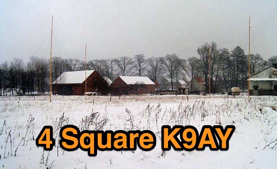 4 Square K9AY Array project for 80 and 40 meters band
 -
 Setting up a ZZ Wave antenna, a dual band loop antenna covering 80 and 40 meters.
 -
 The antenna in this project is a modification of the techniques used to design a multiband fan type dipole with little or no tuning involved having a total space of 105 feet
 -
 Isotron antennas are antennas of reduced size, without tuning. On 40 and 80m band, it is made of two plates into v whose angles are connected by a coil. In this article the description of a home made realization for the 40m band.
 -
 A dual band dipole antenna for 40 and 80 meters band. Total lenght of 26 meters, foreseen two coils at aprox 11 meters distance from center feed.
 -
 Documents the OC1I and OC6I IOTA DXpeditions to Peru, specifically highlighting operations from SA-098 (Isla La Leona) and SA-076 (Isla Lobos de Afuera). The OC1I team logged over **8000 QSOs** from SA-076, while OC6I made 1400 QSOs from SA-098, despite challenging propagation conditions. The resource details the equipment used, including an _IC-7000_, an IC-706mkIIG, and a TS-440SAT, along with various antennas such as a 160m dipole, FD4, G5RV, and a multi-band vertical for 17m, 20m, 30m, and 40m. The DXpedition dates are specified: OC6I operated from SA-098 between December 28 and December 30, while OC1I was active from SA-076 from January 2 to January 7. Both operations are confirmed as valid for IOTA credit. The page also includes a video link for the OC6I operation and a photo gallery from the DXpedition. Feedback is welcomed, and the webmaster is identified as Bodo Fritsche, DL3OCH.
 -
 An antenna for 80 meters band for those who does not have enough space to setup a halwave wire dipole that is aprox 130ft or 40 meters. The antenna is an open-wire-fed shortened dipole
 -
 An inverted V Dipole antenna for HF bands, working on 10 20 40 and 80 meters band. PDF Presentation
 -
 Full article on how to build a home-made wire dipole antenna for 40 and 80 meters band. Article is fully in italian, as it was published on ARI RadioRivista, but is plenty of self explaining pictures that will guide you on homebrewing this trapped dipole antenna for the lower amateur radio bands.
 -
 A portable (15.5 foot diameter) NVIS loop for 3.5 to 7.3 MHz. Performs well at high and low takeoff angles, and has smaller footprint than most NVIS antennas.
 -
 A loop antenna for 80 and 40 meters band, the main loop is based by a crossed line using aluminium strip lines. The main loop diameter is 150 cm.
 -
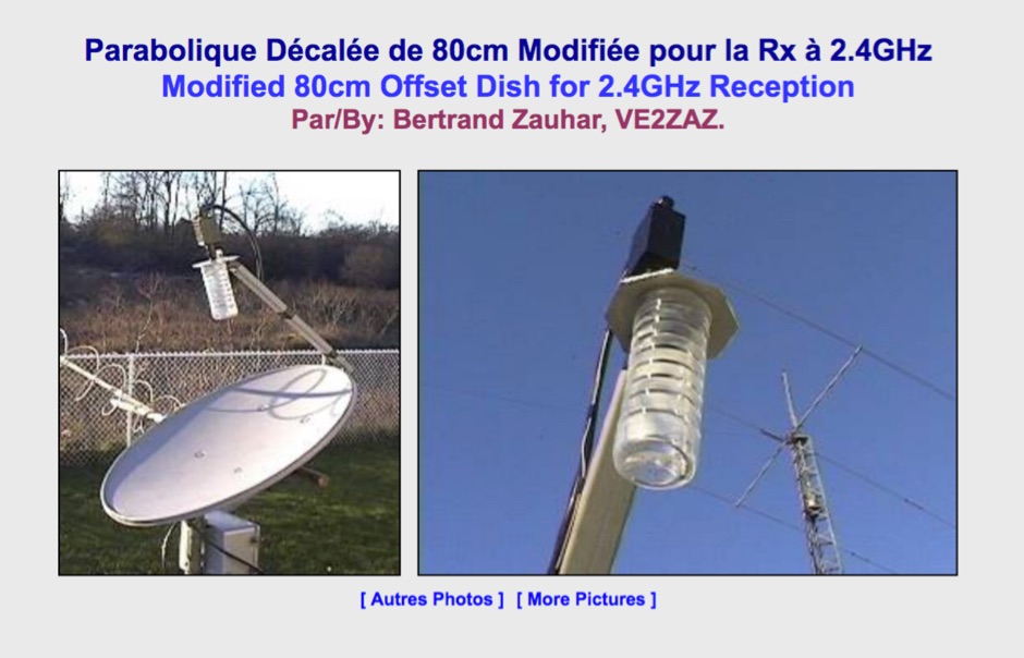 Modified 80cm Offset Dish for 2.4 GHz Satellite Reception. This 50-ohm impedance antenna allows, when connected to 2.4GHz preamplifier and downconverter, to receive Amateur satellites with 2.4GHz transponders such as AO-40.
 -
 A simple portable dipole antenna for the 40 meter band using a total lenght of 18 meter. It can be used for 80 to 10 meters coverage using a antenna tuner.
 -
 Designing and constructing a two-element receiving loop antenna array for HF operation involves specific considerations for achieving high directivity and noise reduction. This resource details a homebrew system comprising two 30-inch diamond-shaped loops, spaced 20 feet apart, which are fed through mast-mounted preamplifiers and passive signal combiners. The operational principle relies on adjusting phase delays between elements via precise _Belden 8241_ coaxial cable lengths, optimized for specific bands from 160m to 20m. Performance data, derived from _EZ-NEC_ modeling, illustrates consistent 90° azimuth-plane beamwidth and low take-off angles across the target bands, with _Receiving Directivity Factor_ (RDF) values comparable to a 300-foot Beverage antenna. The article presents detailed elevation and azimuth plots for 20m, 30m, 40m, 80m, and 160m, demonstrating the array's ability to provide strong response at low DX angles while also supporting _NVIS_ signals. Key components like the _DX Engineering RPA-1_ preamplifier and _DXE RSC-2_ signal combiner are discussed, alongside the importance of impedance matching to preserve antenna patterns. The construction emphasizes self-contained elements that do not require ground radials, offering a compact solution suitable for suburban environments and stealth installations, with a focus on optimizing receive performance independently from transmit antennas.
 -
 The ZS1J/B beacon operates on 28.2025 MHz with 5 Watts output to a half-wave, end-fed vertical antenna, initially installed in 1977 as ZS5VHF near Durban. The 10-meter transmitter is a modified 23-channel CB radio, and the identification keyer uses a diode matrix unit with TTL ICs from the same era. After relocation to Plettenberg Bay in 1993, the beacon has been in continuous service, with additional QRP transmitters later installed for other bands. In 1994, a single-transistor, 80-meter, 0.5-watt QRP transmitter with a half-wave dipole was added on 3586 kHz, followed by a 160-meter, 0.5-watt unit on 1817 kHz. A 30-meter, 0.5-watt transmitter was installed in 1996, operating on 10.124 MHz. In 2002, a 40-meter QRRP beacon on 7029 kHz, with an output of 100 microwatts, achieved DX reports up to 1100 km from ZS6UT in Pretoria. Best DX reports for the 80m and 160m beacons came from 9J2BO.
 -
 Low-frequency (LF) radio time signals, operating primarily in the 40–80 kHz range, are broadcast by national physics laboratories for precise clock synchronization. Transmitters like **JJY** (40 kHz, 50 kW; 60 kHz, 50 kW), RTZ (50 kHz, 10 kW ERP), MSF (60 kHz, 15 kW ERP), WWVB (60 kHz, 50 kW ERP), RBU (66.66 kHz, 10 kW), and DCF77 (77.5 kHz, 50 kW) cover vast geographic areas, often several hundred to thousands of kilometers. LF signals offer distinct propagation advantages over higher-band transmissions such as GPS. Their long wavelengths (3–6 km) enable effective diffraction around obstacles like mountains and buildings. The ionosphere and ground act as a waveguide, eliminating the need for line-of-sight and allowing a single powerful station to cover extensive regions. Ground wave propagation minimizes ionospheric variability effects on transmission delay, and signals penetrate most building walls effectively. Robust and low-cost receivers, often priced at 20–30 USD/EUR, are widely used in radio clocks. These receivers typically comprise a tuned ferrite core antenna, a receiver IC (e.g., Atmel T4227, U4223B, MAS1016) for amplification and AM detection, and a microcontroller for decoding the time signal and phase-locking a local clock. Specific components for DCF77, MSF, and WWVB are readily available from vendors like HKW Elektronik and Ultralink.
 -
 A portable operation experience with a SpiderBeam pole during a contest, testing wire antennas, like dipole and delta loops configurations on 20 40 and 80 meters band.
 -
 The Buddistick antenna, as demonstrated by KP4MD, effectively handles up to **250 watts** and provides coverage from 40 through 10 meters, with an optional coil extending operation to 80 and 60 meters. KP4MD's video presentation meticulously describes the antenna setup, emphasizing the critical role of the _shunting coil_ for achieving resonance on lower bands like 40 and 80 meters. This practical approach highlights how a compact antenna can deliver solid performance from a constrained location. SWR curve diagrams are included, clearly illustrating the impact of the shunting coil on the antenna's resonating frequency. These visual aids provide concrete evidence of the adjustments needed for optimal operation across different bands, particularly when space is at a premium. KP4MD's insights are particularly valuable for hams operating from apartments or other limited spaces, showcasing real-world results from a balcony installation.
 -
 An interesting article on end fed half-wave wire antennas with a couple of original experiments. Author illustrate the role of the QRP matchbox, and a 40/20 meter antenna with a center stub making it a large bandwidth antenna for 40 and 20. Includes also an 80/40 end fed with the typical coil to make it available on 80 merts band.
 -
 High Speed Multimedia (HSMM) radio, as introduced by John Champa, K8OCL, represents a significant advancement in amateur radio's digital capabilities, moving beyond traditional keyboard modes like packet radio. This initiative, driven by ARRL's Technology Task Force, focuses on developing high-speed digital radio networks capable of up to 20 megabits per second. HSMM primarily facilitates digital voice (DV) and digital video (ADV), enabling real-time video transmission from emergency scenes to an EOC without expensive ATV gear, often requiring only a laptop, a PCMCIA card, a digital camera, and a small antenna. The working group's initial efforts concentrate on cultivating microwave skills within the amateur community to build and support portable and fixed high-speed radio-based local networking, or **RLANs**. These networks prove invaluable for RACES and ARES organizations, as well as homeland security and other emergency communications. Field Day exercises and simulated emergency tests (SETs) are encouraged to hone skills in rapid site surveys and deploying broadband HSMM microwave radio networks, with examples like linking Field Day logging stations or antenna test results at the Midwest VHF-UHF Society Picnic 2003. Getting started with HSMM often involves adapting off-the-shelf **IEEE 802.11** (WiFi) equipment to comply with amateur radio regulations, typically operating in the 2.4 GHz ISM bands. While consumer WiFi gear has range limitations under Part 15 rules, proper setup under amateur regulations can extend coverage significantly, with test networks like the Hinternet achieving 5-15 mile ranges at 54 M bit/s using small mast-mounted dish antennas. Careful selection of equipment with external antenna ports, high transmit power, and low receive sensitivity is crucial, along with using low-loss coaxial cable like LMR-400 for optimal performance at these frequencies.
 -
 This magnetic loop DIY site is ment to be an introduction into making DX high quality magnetic loop antennas that will beat any dipole
 -
 No matching adjustments needed. Directly perfect match to 50 Ohms using a remotely switched wideband transformer
 -
 This type of antenna is a popular antenna design as the performance is very good across the HF bands and requires little or no tuning. It’s a dipole fed off center with a 4:1 balun at the offset feed point. The antenna shown covers 80, 40, 20 and 10 meters. The formula can also be used to adjust the overall length to cover more or fewer bands and the resulting overall length. 160-10m, 80-10m or 40-10 meters depending on your available space. Other bands will require a tuner.
 -
 A dedicaed vertical antenna for 80 meters band based on a 40 meter vertical experiment
 -
 A 60-foot available space, for example, might necessitate a shortened multiband dipole array to cover 80, 40, and 15 meters effectively. This resource details the construction of such an antenna, combining full-size and coil-loaded dipoles on a single feedline. It addresses the common challenge of fitting multiple HF bands into restricted physical footprints, providing practical guidance for hams with smaller backyards or portable operations. The core of the offering is an interactive calculator that determines required loading coil inductance and dipole lengths for various amateur bands from 160m to 10m. Users input their available space, and the tool provides dimensions, coil turns, and an efficiency rating (Good or Fair) based on the antenna's electrical length relative to a quarter-wavelength. It also suggests suitable _PVC_ pipe diameters for coil forms. The article further illustrates a center feed-point assembly using an 18-inch section of 2-inch _PVC_ pipe, detailing eye-bolt spacing and coaxial connector installation. It emphasizes the importance of adequate spacing between parallel dipoles and offers customization options for the feed-point, including the addition of a _Balun_ for improved feedline isolation.
 -
 Experimenting with capacitive antennas for 40 and 80 meters band. A very space-saving antenna with good receivings caracteristics
 -
 A 3 band dipole antenna for 40-80-160 meter bands, It's made with easily available materials and is designed for inverted V mounting. The antenna is shortened for these bands, but still manages to make contacts in 80m and 160m with stations in Canada and the USA. The construction details are provided, including the dimensions of the antenna elements and the traps. The antenna is easy to build and provides good performance in all three bands. In Italian.
 -
 With this antenna the coverage is 80,40,20,15 and 10 meter band without any antenna tuner and the average SWR is below 1.2 on phone bands. The total antenna lenght is about 23 meters , with one 20.4 meters long segment from the 1:49 transformer to the 110uh coil and about 2.2 meters long segment from the coil to the insulator.
 -
 The Linked Dipole is a multiband antenna designed for 80/60/40/30/20m bands, optimized for the (tr)uSDX low bands configuration. It incorporates a 1:1 Balun to prevent common mode currents, ensuring balanced operation with coaxial cable. The Balun, wound on an FT140-43 core, achieves 37-40dB attenuation. The design includes a 3D-printable housing for compactness and waterproofing, with labeled link insulators for ease of use. Wire lengths were meticulously adjusted for optimal performance with a 7m pole and 3m rope extension, ensuring the antenna's ends are off the ground for improved behavior. The project includes downloadable printables for DIY construction.
 -
 Vertical end fed antenna used for portable operations. The antenna will work on 80 with acceptable results, it will work fine on 40m, and it will be a good deal better than a normal 1/4 wave GP on 20, 17, 15 meters.
 -
 Experimentin wire antennas on top band using several type of aerials. This includes a 40 to 160 meters EndFed Half Wave kite antennas and 160m/80m loaded vertical antenna.
 -
 Listen to online WebSDR located in Andorra Europe. Four receivers on 60m, 20m, 40m, and 80m, connected to a dipole antenna direction East/West
 -
 A dual band 40-80 vertical antenna on an 18m Spiderbeam Fiberglass Spiderpole, with monoband performance
 -
 This article documents the author's journey in building, modifying, and testing a DIY short vertical antenna for 40, 30, and 20 meters, with potential 80m capability. Initially inspired by Parks On The Air (POTA), the author explores pedestrian mobile operation and details various experiments to enhance antenna performance. The piece highlights challenges, SWR tuning, portability, and practical results, emphasizing a balance between efficiency and size. Ultimately, it showcases the adaptability of DIY antennas for portable ham radio applications.
 -
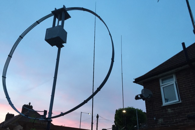
 The author reflects on expanding their antenna for 80m coverage during lockdown. They extend the End Fed Half Wave (EFHW) using a Spiderbeam pole and "cheating" by dog-legging across their garden. Despite challenges, they achieve coverage for multiple bands with minimal cost. Practical Wireless features EFHW antennas, including a pre-made 20m EFHW extended for 40m.
 -
 1260 MHz yagi antenna for ATV with a total Bandwidth (3 dB) 1240-1280 MHz and 10 dBd gain
 -
 How to Design and Build a Field Expedient End-Fed Half-Wave Antenna for 20m, 40m and 80m. This Shorty 80m EFHW comprises a 49:1 autotransformer (to match the very high impedance at the end of a half-wave wire), a half-wavelength wire for 40m (also a quarter-wavelength for 80m), a loading coil and a short tail wire. The coil and the short tail wire (about 6 feet) make up the other quarter wave on 80m.