Search results
Query: alc design
Links: 164 | Categories: 3
-
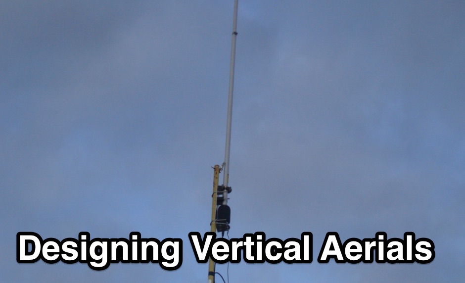 If you want to design vertical antennas you can find all theory and formulas used to model a vertical aerial calculating capacitance, reactance, building the inductor and calculating resistances. Includes an excel spreadsheet to calculate efficiency.
 -
 This web article details the construction of a 4-meter band coaxial dipole antenna, designed for operation between **70.000 MHz and 70.500 MHz**. The resource provides a bill of materials and step-by-step assembly instructions for a half-wave dipole constructed from _RG-58_ coaxial cable. The design specifies a direct 50 ohm feedpoint impedance, eliminating the need for an external matching network. Construction photographs illustrate the stripping and soldering processes for the coaxial cable elements, ensuring proper electrical connection and physical integrity. The article includes specific dimensions for the radiating elements, derived from calculations for the 70 MHz band. The project outlines the physical dimensions required for resonance at 70 MHz, with the outer braid forming one half and the inner conductor forming the other. The feedline connection is directly to the coaxial dipole's center, maintaining a 50 ohm characteristic impedance. While the article does not present SWR plots or VNA sweeps, it focuses on the mechanical construction and dimensional accuracy for achieving a functional 4-meter dipole. The design is intended for fixed station use, with no specific mention of polarization or height above ground, but implies a standard horizontal orientation for dipole operation. DXZone Focus: Web Article | 4m Coaxial Dipole | Construction Guide | 50 ohm Feed
 -
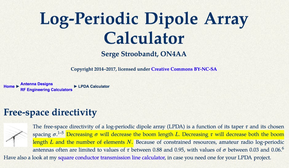 This LPDA calculator is based on the design procedure as described by L. B. Cebik, W4RNL (SK) in the 21st edition of The ARRL Antenna Handbook.
 -
 Designer and supplier of tower reinforcement systems to the wireless industry.
 -
 The calculator designs the Yagi-Uda antenna based on the DL6WU model with boom correction, following the G3SEK-DL6WU method. It optimizes the antenna for maximum gain and allows adjustment of passive elements without affecting SWR. DL6WU antennas are known for their high gain, minimal sensitivity to nearby objects, and stable performance in various weather conditions.
 -
 Online Constant - k Lowpass Filter calculator
 -
-
 When assembling a robust shack, the quality of interconnects often determines overall system integrity and signal fidelity. Neutrik, with over 50 years in the connectivity sector, specializes in professional-grade connectors that withstand rigorous use in entertainment and industrial applications. Their product range includes XLR, speakON, powerCON, and opticalCON series, which are frequently adapted by hams for critical station infrastructure, particularly in contesting or DXpedition environments where reliability is paramount. Amateur radio operators often repurpose these durable connectors for antenna switching matrices, audio interfaces for digital modes, or power distribution systems. The robust locking mechanisms and high-quality contact materials found in Neutrik products ensure stable connections, minimizing intermittent faults that can plague field operations or even fixed station setups. This attention to mechanical and electrical integrity aligns well with the demands of high-power RF environments and sensitive receive chains. While primarily serving the pro-audio and video markets, the engineering principles behind Neutrik's designs translate directly to the needs of radio amateurs seeking superior performance and longevity from their cabling and connection points. Their commitment to innovation, as highlighted by their 50-year journey, suggests a continuous evolution of products that could benefit future amateur radio applications.
 -
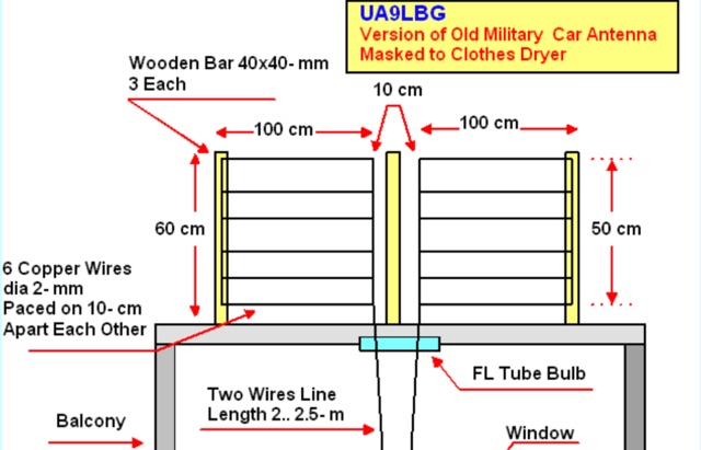 The antenna almost repeat the design of the Car Antenna however instead of aluminum tubes it was used copper wire in plastic insulation in diameter of 2- mm (12 AWG).
 -
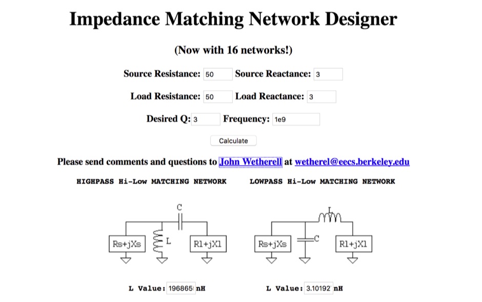 An online multiple calculator of 16 impedance matching networks
 -
 Constructing a basic multimeter involves integrating a 0-1mA meter movement with various shunts and multipliers, selected via a switch, to create a versatile instrument capable of measuring DC volts, current, and resistance. The design outlines two main units: a primary unit handling six DC current ranges up to 1 amp and eight DC voltage ranges up to 1000 volts, alongside an internal battery for an ohms range up to 200,000 ohms. This approach allows for a practical, hands-on understanding of meter operation. An add-on unit further extends the multimeter's capabilities, incorporating a meter rectifier and switched series resistors to provide four AC voltage ranges up to 100 volts. Additional shunt and series resistors, designated Ra and Rb, are included to expand the instrument's range to 10A and 5kV, demonstrating how modular design can enhance functionality. When this add-on is in use, the main instrument is set to measure 1mA FSD, connecting via specific lugs. Component selection emphasizes precision, with 1% tolerance high stability resistors for series elements and Eureka resistance wire for shunts. The design specifies values calculated for a meter with 60 ohms internal resistance, noting that these would require modification for different meter characteristics. Experimental adjustment of shunt values is recommended to ensure accurate readings against a calibrated reference meter, reinforcing practical calibration techniques.
 -
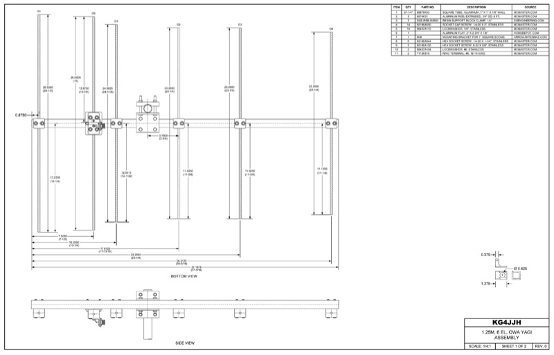 Presents an alternative construction method for isolated element Yagi antennas, specifically for VHF/UHF operation. The technique utilizes commercially available vibration damping clamps (resin support blocks) to isolate 1/4-inch aluminum rod elements from a 1-inch square aluminum boom, simplifying the build process by eliminating the need for custom-machined insulators. This approach is demonstrated through the construction of 6-element Optimized Wide-Band (OWA) Yagis for the 2-meter, 1.25-meter, and 70-centimeter bands, which are well-suited for portable contesting arrays due to their light weight and decent gain. The document provides detailed specifications for element and boom materials, along with step-by-step procedures for cutting, drilling, and tapping. It also covers the fabrication of a feedpoint bracket for a direct 50-ohm SO-239 coax connection and discusses considerations for horizontal versus vertical polarization, including mast placement. The resulting 6-element models achieve an average free-space gain of 10.2 dBi and a 25 dB front-to-back ratio, with the construction technique being scalable for higher gain designs. Included are parts lists with sources, detailed mechanical drawings for each band, and EZNEC data for the 2-meter and 70-centimeter designs, showing both free-space and 30-foot elevation performance. The designs are optimized from W4RNL's original concepts using HAMCALC, ensuring good gain, passband characteristics, and front-to-back ratios for wideband Yagi operation.
 -

-
 A 0-30 MHz step attenuator, constructed from switchable Pi attenuation pads, provides a practical tool for evaluating receiver sensitivity and calibrating S-meters. The design utilizes readily available 5% tolerance resistors, with values derived from paralleled components to achieve specific attenuation steps. A schematic (Fig 1) illustrates the circuit, including PCB pad shielding, while a table details required and actual resistor values, along with percentage differences. Measurements of voltage input versus output at various frequencies are used to calculate dB attenuation, presented in a graph (Fig 4). The resource includes formulas for determining output voltage from a known input and a comprehensive 0-40 dB voltage multiplier table, which is crucial for precise signal level management. The project also references external attenuator calculators and equations for further study. Photos (1-3) provide visual guidance for the assembled unit, showing bottom, top, and front views. The project emphasizes the use of **Pi attenuation pads** and **receiver sensitivity** evaluation, offering a hands-on approach to RF signal management.
 -
 The Tri-pole antenna, a clever modification of a standard dipole, allows for dual-band operation by integrating a third element. This design effectively shortens the overall dipole length by 10 to 20 percent, simplifying antenna rotation and offering a compact footprint. KK4OBI's article delves into the operational principles, using a 6 and 10-meter Tri-pole as a primary example, and provides comprehensive instructions for constructing any Tri-pole antenna within the 6 to 15-meter range. Key to the Tri-pole's performance is its off-center feed, necessitating a common mode choke at the feed point for optimal tuning and reduced noise. The author outlines a methodical approach to determining element dimensions, starting with a vertical element frequency calculated as 0.47 times the sum of the desired upper and lower band frequencies. This calculation, along with K-values derived from trend lines, guides the initial lengths for the horizontal arms, demonstrating how a 10m-6m Tri-pole can achieve a total horizontal length 78% shorter than a conventional 10-meter dipole. Tuning and balancing are critical, with the article detailing adjustments to arm lengths and the vertical element to achieve balanced SWR values, as validated through 4NEC2 simulations. Radiation patterns are analyzed at various elevations, showing gains around 5.7 dBi and favorable take-off angles for DX contacts. Construction details specify aluminum tubing dimensions, U-bolts, and an SO-239 connector, emphasizing the importance of a ferrite-based choke for wideband operation.
 -
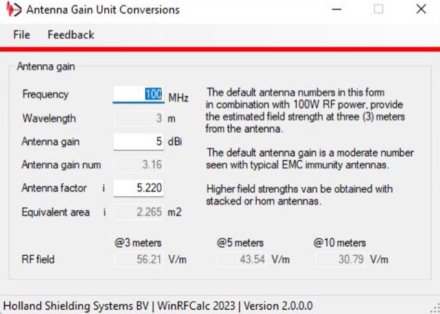 A multi tool Windows program that has been designed to offer the EMC RF and Radio Engineer a large variety of tools for Attenuation calculation, VSWR analysis, FIR Filter calculations, EMC system configuration, Radar testing , RF Filter calculation and much more without the need of a live internet connection.
 -
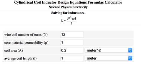 Calculate inductance online, with the cylindrical Coil Inductor Design Equations Formulas Calculator
 -
 A basic YAGI UDA online antenna calculator, accept as input frequency, number of elements, diameter of parasitic element and boom diameter. This online calculator will generate a basic design data including each element length and spacing.
 -
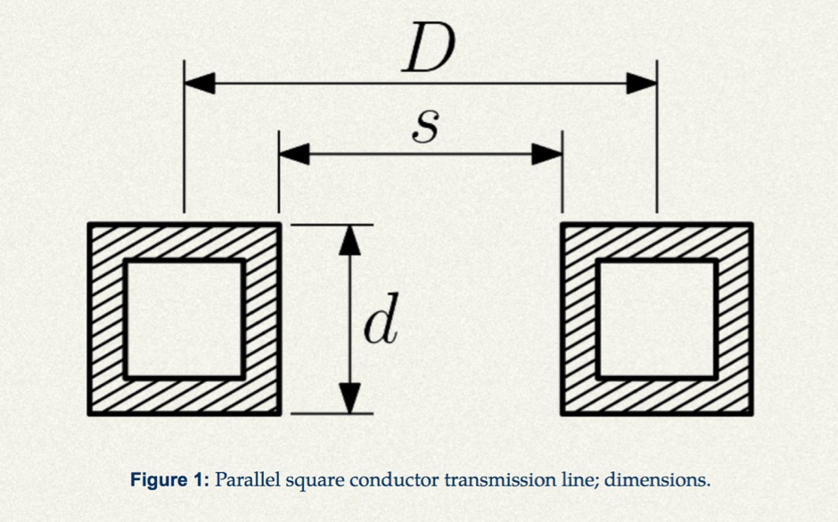 Design a parallel square stock balanced transmission line with this calculator.
 -
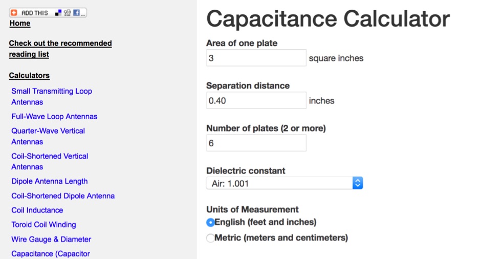 An online calculator for designing and evaluating capacitors based on the capacitor's area, separation, number, and dielectric constant
 -
 Microwaves101 provides an extensive repository of information covering fundamental principles of microwave design, targeting engineers and radio amateurs interested in the higher frequency spectrum. The site features a detailed _encyclopedia_ of microwave terms and concepts, alongside practical design considerations for various components and systems. It serves as a foundational reference for understanding RF propagation, transmission lines, and active/passive microwave circuits. The resource includes numerous calculators for impedance matching, filter design, and other critical RF parameters, facilitating hands-on project development. Discussions on **10 GHz** equipment and **24 GHz** projects highlight practical amateur radio applications, extending to operations up to 134 GHz. Content spans from basic theory to advanced topics like MMIC design and antenna characteristics, supporting both educational and practical endeavors in microwave technology.
 -
 DL7JV shares his practical experience building and testing capacitive antennas, initially skeptical of their performance compared to magnetic loops and mono-band dipoles. His interest was piqued after hearing a Spanish station running 100 Watts on 80 meters with a 1-meter Micro Vert, making DX contacts into PY and UA0, despite the antenna being only 4 meters high in a garden. This prompted DL7JV to investigate further, consulting resources from DL7PE and DL7AHW, the latter providing DOS programs like "Mitspule.exe" and "Spulenprg.zip" for calculating antenna dimensions and coil conversions. The article outlines the construction of two prototype antennas: one for 7.050 MHz using a 75mm PVC pipe and another for 3.550 MHz with a 110mm PVC pipe. Both designs feature aluminum foil condensers and coils wound from 1mm² H07V-K wire. DL7JV provides specific measurements for the condenser capacitance, surface area, diameter, height, coil inductance, turns, and wire length for both 40m and 80m versions, along with RG58 feedline lengths. Initial reception tests for the 7 MHz antenna, placed indoors, yielded impressive S9+5 signals from a German station compared to an S8 from a 42-meter roof-mounted loop, even hearing a Japanese station. Transmission attempts on April 4, 2004, despite moderate solar storm conditions, resulted in successful QSOs on 7 MHz with EA5OT (579/559) and on 3.5 MHz with YT1NT (579/559) and G4KKI (579/559) using 100 Watts. DL7JV notes the antenna's sensitivity to coordination and feedline layout, suggesting a modification from DL7AXO involving a 500pF fixed capacitor and coil tap for improved SWR stability. He concludes that while the capacitive antenna is space-saving and performs well for reception and 100W transmission indoors, its transmit performance doesn't yet match larger antennas, with further outdoor field tests planned. DL7JV also intends to build a 1.8 MHz version.
 -
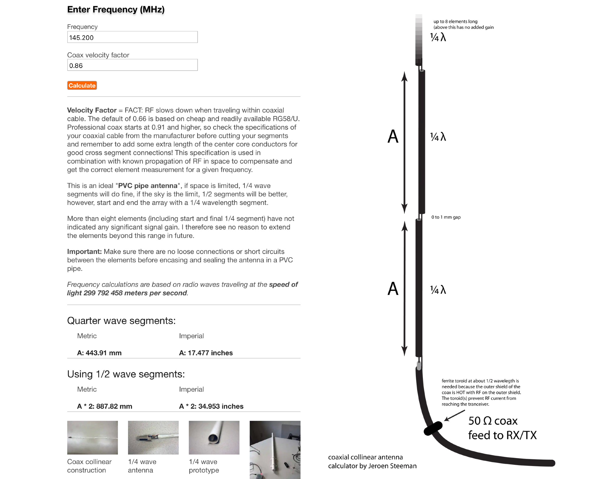 This page offers an online antenna designer tool for Hams to calculate the dimensions needed to construct a coaxial collinear antenna for a specific frequency. It provides guidance on the required frequency input, coax velocity factor, and element measurements for optimal performance. The tool is recommended for experienced antenna builders due to its complexity and technical requirements. Users can input the frequency in MHz and the tool will generate the necessary dimensions based on the chosen parameters. The page emphasizes the importance of accurate measurements and connections for successful antenna construction.
 -
 This article shares the author's experience with building antennas. After putting a large magnetic loop project on hold, they decided to try a base-loaded vertical antenna. The author explains how they chose to design a new antenna from scratch, aiming for a frequency of 7 MHz. They describe the calculations needed to find the right coil inductance and how they used 3D-printed parts for the construction. The article wraps up with results from their initial tests, showing good communication on different bands and highlighting the success of their design.
 -
 The HF Beacon Tracker is an advanced interactive tool designed for DXers and ham radio opoerators in general to monitor active beacons operating below 14 MHz. Built upon a high-fidelity 3D Earth globe, the application provides a spatial perspective on signal paths by integrating real-time environmental data with a comprehensive beacon database curated by Mirek OK1DUB. Beacons are plotted using precise Maidenhead locators and feature a real-time day/night terminator overlay to help operators identify Gray Line propagation opportunities. With a single click, users can calculate the exact distance from their own QTH to any beacon, visualized via an animated Great-Circle Path arc on the globe surface. To enhance its diagnostic capabilities, the tool seamlessly integrates with PSK Reporter, allowing users to right-click CW beacons to instantly fetch current reception reports and signal strength data. The interface is fully optimized with a mobile-responsive design, smooth globe rotation, and togglable Dark/Light themes suitable for any shack environment. Whether you are performing antenna gain tests, conducting ionospheric research, or simply hunting for band openings, the HF Beacon Tracker transforms raw database information into an intuitive, visual diagnostic suite. It serves as an essential asset for any operator looking to master HF band conditions.
 -
 This article describes the construction of a 9,50 m long dipole for the 30 m band (10.1 MHz to 10.15 MHz). It was designed to be mounted ca. 6Â m above ground inside an attic. The calculations were performed by OE1MEW
 -
 The antenna I built was inspired by a portable delta loop designed by Doug DeMaw, W1FB. Given that I constrained myself to a 50-foot roll of speak wire, I scaled my antenna for the 20M band. Using the formula, 1005 divided by the frequency in megahertz, I calculated a total length of 71 feet (21.6 meters) for the center of the 20M band.
 -
 The HB9CV antenna calculator aids amateur radio enthusiasts in designing antennas for VHF and UHF bands. By inputting the working frequency, users can obtain crucial dimensions like dipole lengths and distances. The tool, based on the HFSS antenna model, provides data on impedance, VSWR, and gain, optimizing front/back radiation ratios. It includes tips for fine-tuning using a Г-matching balun and compensating capacitor, ensuring effective performance and minimal VSWR for enhanced radio communications and direction finding.
 -
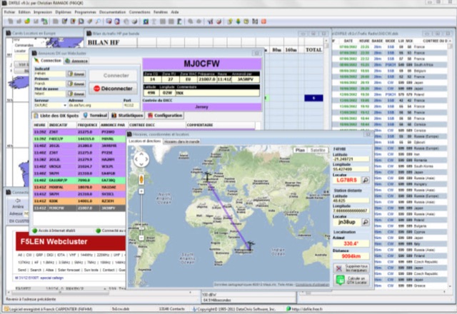 DXFile is a Windows shareware application designed for amateur radio operators, providing comprehensive log management capabilities. The software, developed in Pascal, facilitates real-time and deferred QSO entry, automatically populating fields like frequency, mode, and DXCC country based on user input and system time. It includes features for searching, modifying, and deleting QSO records, with options to sort logs by date, callsign, or entry order. The program offers various printing functions, including QSL card labels in multiple formats, and can generate standard logbook printouts. Beyond basic logging, DXFile integrates modules for tracking progress towards major operating awards such as DXCC, _IOTA_, WAZ, WAS, DDFM, and DIFM. It provides detailed summaries of contacts by band and mode, including graphical representations of HF traffic. A dedicated QSL Manager module assists in processing received QSLs, allowing users to mark confirmations and print multi-line QSL labels. The application also incorporates a DXCC list viewer, which can be updated to ensure accurate country and zone data for logging and award tracking. A distinctive feature is its HF propagation prediction module, which calculates optimal frequencies and signal levels for paths between **250 km** and **6000 km**, considering both E and F layer ionospheric conditions. This module helps operators determine the best times for long-distance contacts. Additionally, DXFile includes a _Web-Cluster_ interface, enabling connection to various DX cluster servers like DXLITE, DXSCAPE, and NC7J for real-time spot information.
 -
 Learn how to design and analyze a folded trifilar antenna for the 80-meter band. Based on a description from RAF antennas between 1940 and 1970, this article provides step-by-step guidance on modeling the antenna, calculating resonance frequency, adjusting dimensions, and verifying performance. Perfect for hams looking to improve their antenna setup for better transmission and reception on the 80M band.
 -
 Presents a detailed construction guide for a 9 dB, 70cm collinear antenna, utilizing readily available _RG58/U_ coaxial cable and PVC pipe for housing. The resource outlines the critical calculations for ½ wavelength sections at 444 MHz, incorporating the coaxial cable's velocity factor of 0.66, which yields a section length of 223 millimeters. It specifies the preparation and soldering of eight such half-wavelength sections, each cut to 231mm to allow for trimming, forming the core of the array. Further instructions detail the integration of a ¼ wave element (169mm #16 solid wire) at the top and a ¼ wave aluminum tube (160mm, 5/16 inch) at the bottom, crimped to the feed point's braid. The guide also addresses RF common mode current suppression by suggesting the use of _FT50-43_ toroids on the feedline. Final assembly steps cover mounting the antenna within ¾" PVC pipe using a wooden dowel, waterproofing connections, and initial SWR checks. The article also discusses scaling the design for different element counts and other VHF/UHF bands.
 -
 The Saturn PCB Toolkit is the best freeware resource for PCB-related calculations you can find. It incorporates many features that PCB designers and engineers are in regular need of like current capacity of a PCB trace, via current, differential pairs and much more. Please download our PCB Toolkit today for free and enjoy!
 -
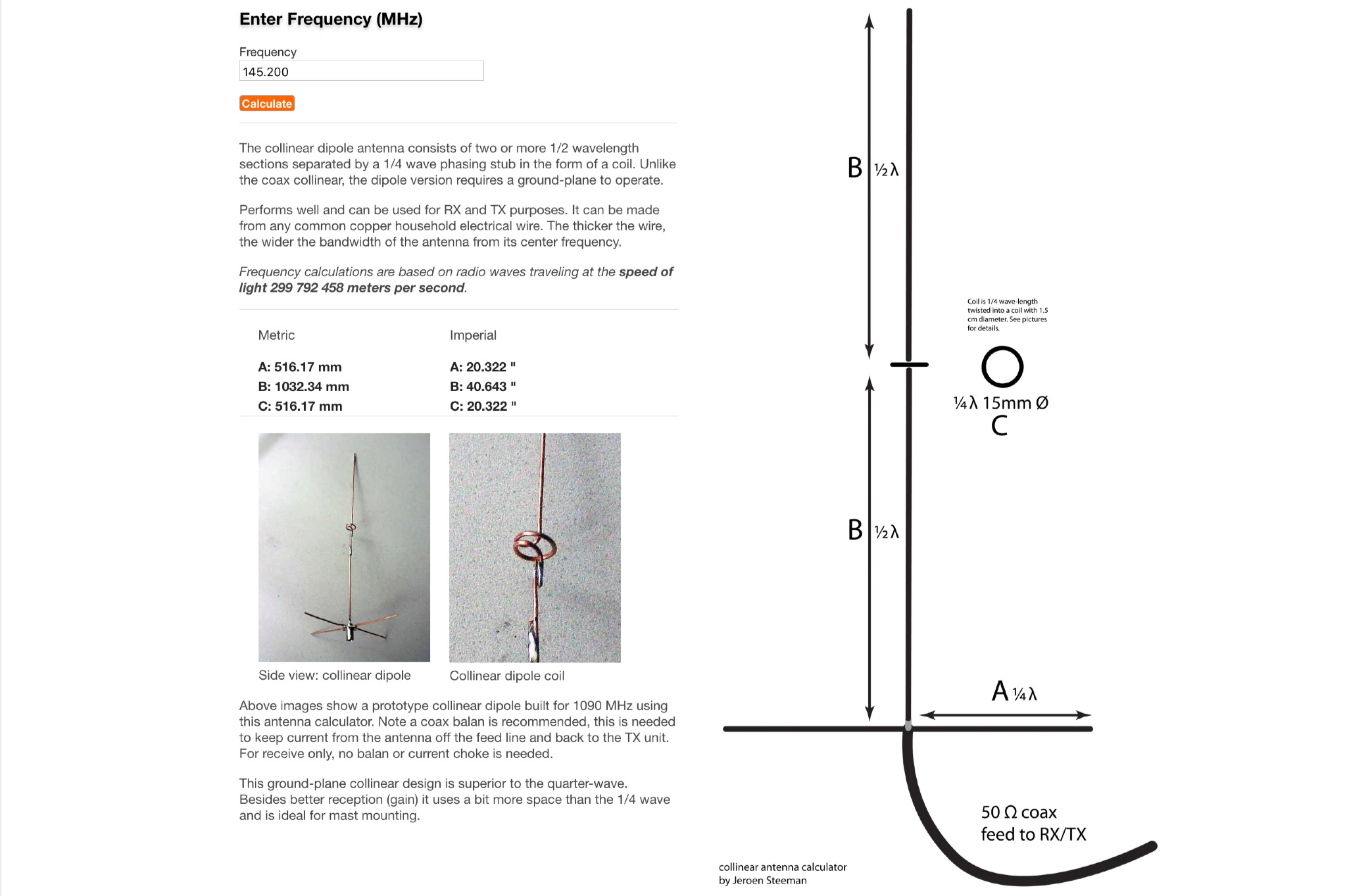 This page offers an online antenna designer to calculate the dimensions for a collinear dipole antenna at a specified frequency. The collinear dipole antenna is constructed with multiple 1/2 wavelength sections separated by a 1/4 wave phasing stub in the form of a coil. It requires a ground-plane to operate and can be used for both receiving and transmitting purposes. The antenna can be made from common copper wire, with thicker wire providing a wider bandwidth. The calculations are based on radio waves traveling at the speed of light. Ideal for ham radio operators looking to build their own antenna for improved reception and transmission.
 -
 The Slim Jim Antenna Calculator is an online tool that helps hams design a Slim Jim antenna for any desired frequency. This extended version of the J-Pole antenna design does not require a ground plane and is perfect for mounting inside PVC piping. The calculator determines the dimensions of the antenna elements based on the input frequency. Suitable for both receiving and transmitting purposes, this antenna can be easily constructed using common household wiring. The tool provides metric and imperial measurements, along with visual representations of the antenna design for easy reference.
 -
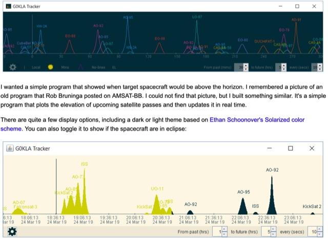 KlaTrack is a Windows-based software application designed to assist amateur radio operators with satellite communication by predicting spacecraft visibility. It provides a simple interface to determine when specific satellites will be above the local horizon, a critical factor for successful two-way contacts via amateur radio satellites. The program processes _Two-Line Element_ (TLE) data to calculate orbital mechanics, offering a practical tool for satellite operators to plan their operating windows. It supports real-time tracking and displays essential pass information. This utility simplifies the complex task of satellite tracking, allowing operators to focus on making contacts rather than manual orbital calculations. While specific gain figures or distances are not quantified, the software's core function directly supports achieving successful satellite QSOs by providing precise pass predictions. It is particularly useful for operators engaging in activities like working the International Space Station (ISS) or other low-Earth orbit (LEO) satellites, where short pass times and precise timing are crucial for maximizing contact opportunities.
 -
 Online antenna calculator for a basic 3 elements yagi uda directional antenna. The described antenna design offers a front-to-back ratio of at least 20 dB, a gain exceeding 7.3 dBi, and a bandwidth (SWR < 2) of approximately 7% around the center frequency. It has an input impedance of 50 ohms when using a straight split dipole, which can be substituted with a folded dipole of the same length, increasing the impedance to 200 ohms. A matching balun is required for coaxial feeder connection, and the boom should be made of a dielectric material, like wood.
 -
 Since 1988, Royal Communications International has been supplying communications equipment designed for the military, professional, and amateur market. We specialize in the sale and service of High Frequency, Single Sideband transceivers that are dependable and easy to use.
 -
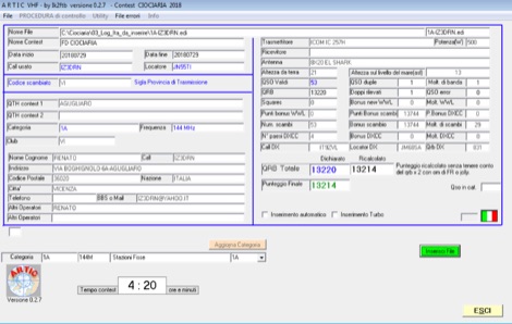 ARTIC is a specialized software tool designed for amateur radio operators participating in VHF contests, offering log checking functionalities. It specifically caters to Italian and Swiss VHF contests, such as the IAC (Italy) and SWAC (Switzerland), ensuring adherence to contest rules and accurate score calculation. The software is developed by IK2FTB and provides a dedicated platform for post-contest log analysis. This resource includes download links for various versions of the ARTIC software, with updates noted for different contest years and rule sets. For instance, versions like ARTIC 2022 and ARTIC 2023 are available, reflecting ongoing development and adaptation to evolving contest parameters. The page also features links to related contest resources and information, providing a centralized hub for VHF contesters to manage their logs and verify their entries.
 -
 The J-pole antenna calculator helps users design custom J-pole antennas for specific frequency bands. It provides dimensions for key antenna sections based on the chosen frequency and material’s velocity factor. The calculator also offers insights into J-pole antenna mechanics, velocity factors, and mounting tips, making it ideal for enthusiasts creating antennas for amateur or mobile radio communications.
 -
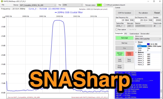 SNASharp is a free software application designed to work with scalar network analyzers compatible with NWT software from DL4JAL. It is used to measure and analyze the scattering parameters (S-parameters) of microwave devices. Provide several measurements and analysis tools including Smith chart, Polar plot, S-parameter tables, Transmission line calculator
 -
 The article details the C-Pole antenna project, emphasizing its portability and ease of setup for amateur radio operators. Key features include its compact design as a vertical half-wave dipole that requires no radials, making it functional at various locations. The antenna employs capacitive loading to reduce physical length while maintaining efficiency. It includes practical advice on resonance tuning, impedance matching, and construction materials, along with a calculator for determining dimensions based on desired frequencies. Overall, it presents a user-friendly solution for portable ham radio communication.
 -
 This DIY guide details constructing a 5-element Yagi antenna for VHF frequencies. Yagi antennas offer directional signal transmission/reception compared to omnidirectional ones. The guide covers material selection (aluminum, screws, etc.), design using software or formulas, and step-by-step assembly including cutting elements, drilling holes, and attaching the coaxial cable. While calculations are provided for a 146 MHz design, adjustments are necessary for different frequencies. Safety precautions and potential result variations are emphasized.
 -
 An **Arduino LC Meter** provides an accessible solution for precisely measuring inductance and capacitance values, crucial for RF circuit design, filter tuning, and troubleshooting in amateur radio applications. This project details the construction of a low-cost, accurate instrument using readily available components, making it an attractive alternative to commercial units for hams and electronics enthusiasts. The build process involves assembling a resonant circuit, integrating an Arduino microcontroller for frequency measurement, and displaying results on an LCD. Key components include an Arduino Uno, a 16x2 LCD, a 74HC14 Schmitt trigger inverter, and a few passive components. The design leverages the Arduino's processing power to calculate L and C values from resonant frequency shifts. Calibration procedures are outlined to ensure measurement accuracy, which is vital for critical RF work. The project includes schematics, a parts list, and the necessary Arduino code, enabling hams to construct a functional LC meter for their workbench.
 -
 The Dipole Bazooka Antenna for 40 meters is a popular choice among amateur radio operators. Its design allows for easy construction using materials like RG58 coaxial cable and PVC. Measurements are calculated using specific formulas; for instance, at a frequency of 7,100 MHz, the total length is approximately 19.74 meters. This antenna offers a performance range of 97% to 99%, with an impedance of 49 to 52 ohms. Additionally, it can handle up to 1 kW of power and requires no modifications for connection.
 -
 EA4EOZ details the construction and testing of 50 MHz traps, a critical component for multiband antenna designs. The project addresses the challenge of sourcing high-voltage capacitors suitable for trap applications, exploring alternatives to expensive doorknob capacitors. The author successfully fabricated a capacitor using 1.6mm double-sided FR-4 PCB material, achieving a capacitance density of **2.6 pF/cm2**. Utilizing the _VE6YP calculator_, specific L and C values of 30 pF and 0.31 uH were determined for a 2cm diameter coil. Both the FR-4 PCB trap and a coaxial cable trap, constructed from _RG-58_, were built and tuned to approximately 50 MHz using a spectrum analyzer. The coaxial cable trap demonstrated superior performance, exhibiting a notch nearly **20dB deeper** than the FR-4 version. This practical comparison provides insights into trap construction for experimental antennas, with the coaxial cable trap selected for an antenna project intended for operation at up to 100 watts.
 -
 Delta loop antennas, particularly the 30 meter variant, offer unique advantages in terms of vertical polarization and omni-directional coverage. The construction process detailed by VE3VN highlights common mechanical and electrical challenges faced by amateur radio operators. Key design considerations include minimizing interaction with existing contest band antennas, achieving low elevation angles for DX chasing, and ensuring the antenna remains off the ground for agricultural clearance. The article provides specific measurements, such as the loop's height and feed point impedance, which are critical for optimizing performance. The use of NEC modeling software illustrates the importance of accurate resonance calculations, revealing how proximity to the tower affects both pattern and impedance. This practical account serves as a resource for hams looking to build effective antennas while navigating typical construction hurdles.
 -
 Addresses the common challenge of constructing effective dual-band antennas for VHF/UHF operations, specifically detailing a J-pole design. It covers the theoretical underpinnings, including calculations for quarter-wavelength radiator and stub sections, accounting for velocity factor and design frequency. The resource provides practical construction guidance using readily available materials like TV twin lead and coaxial cable, culminating in an antenna with a total length of approximately 52 inches. Performance metrics are presented, showing a measured SWR of 1.7:1 or better across most of the 2-meter band and less than 2:1 across the 70-cm band. These SWR measurements, referenced to 50-ohm impedance, were taken at the transmitter end of the feed line. The article also touches upon the necessity of a balun for proper impedance matching between the balanced J-pole and unbalanced coaxial feed line, suggesting a split-core cylindrical ferrite for this purpose.
 -
 Chavdar Levkov, LZ1AQ, presents an experimental comparison of small wideband magnetic loops, building on his previous work on wideband active small magnetic loop antennas. His research focuses on increasing loop sensitivity by maximizing the short-circuit current, which is directly tied to the "loop factor" M = A/L, where A is the equivalent loop area and L is its inductance. Levkov's methodology involves reducing inductance and increasing area through parallel or coplanar crossed (CC) configurations, comparing these designs against a reference single quad loop of 1 m2 area. Experimental verification included testing three distinct loop types: a simple quad loop, two coplanar crossed (CC) loops, and eight parallel loops, all designed to have a total geometric area of 1 m2. Measurements were conducted at 1.8, 3.5, 7, and 10 MHz using a small transmitter 270 meters away, with a Perseus direct sampling receiver for precise signal level assessment. The results consistently showed that CC loops, particularly Loop 5 (two CC circular loops with 1.44 m2 total area), yielded significantly higher currents, up to 9.1 dB over the reference loop at 3.5 MHz, validating M as a reliable predictor of loop sensitivity. Numerical simulations using MMANA further corroborated the experimental findings, demonstrating an almost perfect correlation between the calculated M factor and the induced loop current for 15 different loop models. Levkov concludes that CC loops offer superior sensitivity for a given loop area, while parallel loops are advantageous for minimizing physical volume. Practical recommendations suggest using loops with an M factor greater than 0.5 uA/pT for quiet rural environments, and he provides a spreadsheet tool, WLoop_calc.xls, to aid in optimizing loop configurations for specific operational needs.
 -
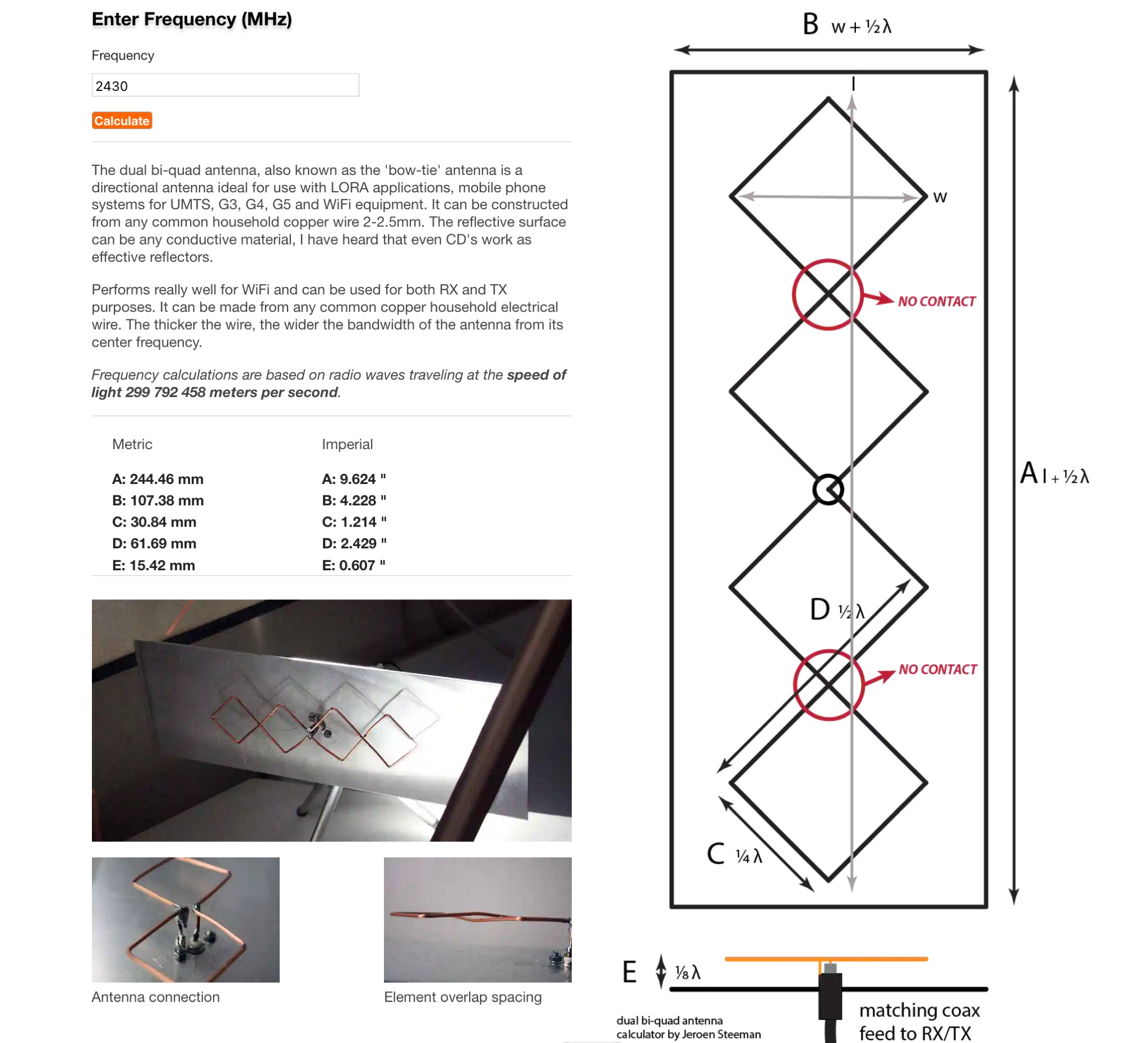 This webpage offers an online antenna designer tool to calculate the dimensions for constructing a double bi-quad antenna for various frequencies. The directional antenna is suitable for UHF and higher frequencies, such as WiFi, UMTS, LORA, and mobile phone networks. It provides dimensions based on the input frequency, making it ideal for hams looking to build their own antennas for specific applications. The tool also mentions using common household materials like copper wire for construction, making it accessible for amateur radio operators with basic equipment.
 -
 The DIY Power Meter project utilizes the _INA226_ high-side power monitoring chip, paired with an ATtiny85 microcontroller, to measure voltage, current, and power, displaying the results on a 128x32 OLED screen. The INA226 communicates via an I2C interface and is programmed with a calibration factor based on the shunt resistance and current register LSB. The project is designed to handle a maximum current of 500mA using a 0.16ohm shunt resistor, which can be adjusted to a 0.2ohm resistor, reducing the full-scale current range to 409mA with a resolution of **12.5uA**. The shunt resistor dissipates only 33mW at maximum current, making 1/4 watt resistors suitable for the setup. The PowerMeter.ino sketch configures the shunt resistance and maximum design current, automatically calculating the calibration factor. The project can be prototyped on a breadboard using an Arduino Uno, employing the Wire library for INA226 and OLED communication, and the u8g2lib library for the OLED display. For the ATtiny85 version, the Adafruit-TinyWireM and Tiny4kOLED libraries are used. The power meter is independently powered by a 3V CR2032 cell, with power switching options including manual switches or DC switched jacks. The low-side n-channel MOSFET switch configuration is tested but introduces voltage drop issues, making manual switching a more reliable option until a suitable DC switched jack is found. DXZone Technical Profile: INA226 | ATtiny85 | OLED Display | Power Meter