Search results
Query: alc design
Links: 164 | Categories: 3
-
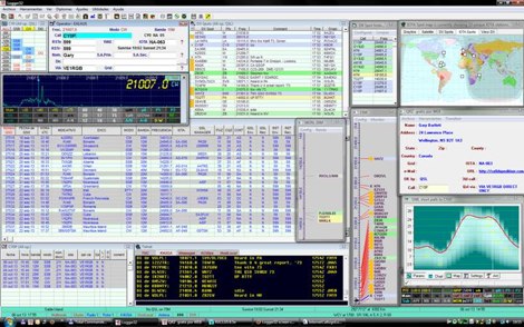 Logger32 is a well-established amateur radio logging program designed primarily for DXers who require a flexible and data-driven logging environment. The software maintains a comprehensive logbook database capable of handling large volumes of QSOs while offering detailed tracking of DXCC entities, awards, and band/mode statistics. One of the core strengths of Logger32 is its DX cluster integration. The program connects to telnet DX clusters and displays spots in real time, with filtering options by band, mode, country, or callsign. The cluster window can automatically highlight needed DXCC entities, band-fills, or new modes based on the operator’s log. Logger32 also provides rig control through CAT interfaces, supporting a wide range of transceivers via serial or USB connections. When properly configured, frequency and mode are automatically captured in the log entry window. The software supports digital mode integration through external applications and can exchange information using standard interfaces. Another important feature is its award tracking system, including DXCC, WAS, IOTA and other common amateur radio awards. The program calculates worked, confirmed, and needed entities with detailed reports. Logger32 supports ADIF import and export, allowing interoperability with other logging systems. It also includes QSL management, with tracking for bureau, direct, and electronic confirmations such as LoTW or eQSL when configured. Overall, Logger32 remains a technically capable logging solution focused on DX tracking, cluster awareness, and detailed statistical analysis of operating activity.
 -
 Author evaluated a custom-built passive AM loop antenna, achieving notable DX reception including KLBJ Austin (230 miles) and WWL New Orleans (700 miles). The antenna operates solely on resonant inductive coupling, enhancing weak signal reception without external amplification. This project illustrates how fundamental RF design—calculating inductance, capacitance, and Q factor—can significantly boost performance of consumer-grade radios. Detailed construction techniques, theoretical background, and optimization strategies for effective loop antenna design are presented for amateur and experimental use.
 -
 Details the construction of a **multiband vertical** antenna, specifically designed for stealth operation in a rented property, covering 80m, 60m, 40m, and 30m. The author, N3OX, leverages a 12m Spiderbeam telescoping fiberglass pole as the primary support, noting its sturdiness compared to typical fishing rods while remaining light enough for quick deployment and takedown. The radiating element is a 14 gauge Flex-Weave wire, attached to the pole's top with a rubber grommet, and fed by 27 bare 18 gauge radials spread across a 40-foot square backyard. N3OX describes the impedance matching solution, opting for custom-built L-networks over a remote tuner to enable fast bandswitching. Using an MFJ-259B and EZNEC modeling, base impedances were measured and component values calculated with G4FGQ's L_TUNER and SOLNOID_3 programs. The 80m coil is wound on a 3.5-inch PVC form, while the 30m, 40m, and 60m coils are air-wound, self-supporting #10 wire. Variable capacitors are incorporated for 40m and 30m shunt elements, with the 60m impedance matched by a series inductor. The project includes a **servo-controlled** homebrew band switch, utilizing a two-pole 12-position ceramic wafer switch for remote operation, addressing the limited 80m bandwidth. The entire matching network is housed in a weather-resistant shelter constructed from lumber and aluminum flashing. N3OX reports good DX results at 100W, estimating the total cost between $150 and $250, depending on existing parts.
 -
 Complete guide to build Jpole antennas with online dimensions calculator.
 -
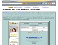 This basic calculator is designed to give the aproximate length (height) of a particular vertical antenna, for the frequency and wavelength chosen.
 -
 Details the construction of a J-vertical antenna specifically for the 10-meter band, offering a practical alternative to a _Slim Jim_ design for 28 MHz. The resource outlines the use of aluminum tubing for the half-wave vertical section and coaxial cable for the quarter-wave matching section, providing specific calculations for element lengths based on frequency and coaxial cable velocity factor. It contrasts the performance of the J-vertical with center-fed dipoles and end-fed verticals, noting superior results in previous comparisons. The article further presents a more recent iteration of the J-vertical, constructed using a fiberglass pole and insulated wire, with updated dimensions for 28.8 MHz. It includes practical advice on weatherproofing connections and securing the antenna for durability against adverse conditions, referencing the survival of an original _J Vertical_ during 110 MPH winds in 1987. The SWR performance is reported as 1.1:1 at 28.6 MHz, maintaining below 1.5:1 across 28.3 to 29 MHz.
 -
 calculates the dimensions and spacings of the elements needed to build a log periodic antenna, given tao, sigma and the lower and upper cutoff frequencies.
 -
 A 9 dB gain 70cm collinear antenna construction is detailed, utilizing eight half-wavelength sections of _RG58/U_ coaxial cable. The design incorporates specific calculations for velocity factor (0.66 for RG58/U) to determine precise element lengths, such as 223mm for a half-wavelength at 444 MHz. A quarter-wave radiating element of #16 solid wire, 169mm long, is added to the top, and a 160mm aluminum tube acts as a quarter-wave counterpoise at the feed point. RF choke baluns, constructed from three _FT50-43_ toroids, are positioned a half-wavelength from the feed point to mitigate common mode current. Assembly involves soldering the coax sections in series, followed by SWR testing during construction and final mounting within a ¾-inch PVC pipe. The article suggests using four half-wave elements for a shorter antenna, noting a potential slight increase in SWR, which can be mitigated with quarter-wave ground radials. The design principles and formulas are scalable for other VHF/UHF bands like 6m, 2m, or 1¼m, providing a versatile homebrew solution for enhanced gain.
 -
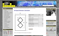
 The Cubical Quad antenna is a popular choice among amateur radio operators due to its robust design and excellent performance characteristics. This resource provides essential scaling formulas that help determine the lengths of the antenna elements and the necessary gamma match values for various frequencies. The design is adaptable, allowing operators to optimize for gain or front-to-back ratio by adjusting the spacing between elements. The accompanying Excel files facilitate precise calculations, making it easier for both beginners and experienced hams to construct their own Cubical Quad antennas. In addition to the design formulas, the resource includes practical insights from the author, who has successfully built and utilized these antennas in various field events. The document outlines the tuning process for achieving minimum VSWR, ensuring optimal performance. With detailed illustrations and performance data, this guide serves as a comprehensive reference for anyone looking to delve into Cubical Quad antenna construction and optimization, enhancing their amateur radio experience.
 -
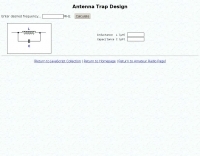
 HamCalc is a free collection of calculators for radio amateurs include Antenna ERP calculations, Attenuators, Audio Filter design, Coil Winding, Decibels, Great Circles map and calculator, HF Filters, HF Traps, Metric conversions OP Amps QRA Locator to Latitude/Longitude, Radio Horizon calculator, Resonance Satellite orbit calculator Timer calculations (555 timer)Zener Diode calculations Download zip By G4VWL
 -
 Design your own 5/8 wave vertical antenna. A simple jscript calculator at Antenna Elmer.
 -
-
 The project details a DIY SWR/Wattmeter designed around an _Arduino Uno_ shield, providing capabilities to measure RF power from 2 to **200 watts** and Standing Wave Ratio (SWR) for HF amateur radio bands. This construction features a compact design, integrating the measurement circuitry directly onto a custom PCB that interfaces with the Arduino Uno microcontroller. Key components include a directional coupler for sensing forward and reflected power, precision rectifiers, and analog-to-digital conversion for processing RF signals. The Arduino firmware handles calibration, calculations, and displays the results on an integrated LCD, offering real-time feedback on antenna system performance. The design prioritizes simplicity for homebrewers. Performance specifications indicate accurate readings within the **2-200W** power range, suitable for typical QRP to medium-power HF operations. The project provides schematics and a basic overview of the software logic.
 -
 J-pole Design Program V1.1 by WA2ISE Download a VHF twinlead Jpole antenna calculator MSDOS program
 -
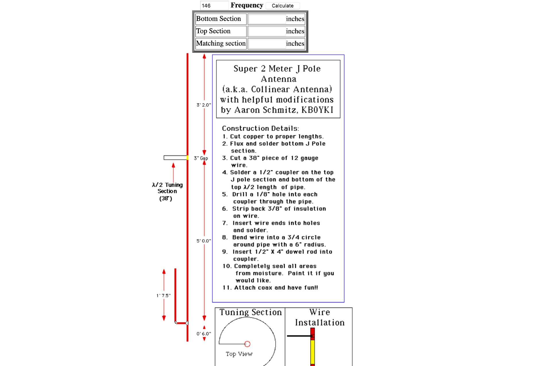 Javascript for calculating the lengths of tubing to be used for the construction of a Super J-Pole in a collinear design
 -
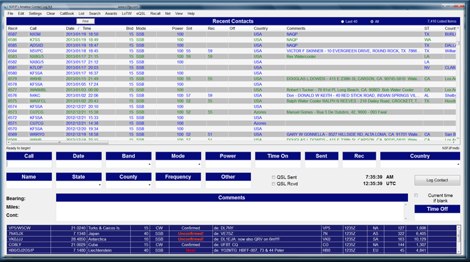 Amateur Contact Log (AC Log) by N3FJP is a commercial Windows-based general logging program designed for amateur radio operators, supporting Windows 7 through 11. It provides comprehensive tracking for various operating awards, including Worked All States (WAS), Worked All Counties, Worked All Countries (WAC), DXCC, VUCC, Grids, Zones, IOTAs, and Lighthouses. The software features a customizable user interface, allowing operators to display specific data fields and adjust font sizes. It includes built-in databases for counties and countries, facilitates queries by band, mode, or power level, and offers a bearing and distance calculator for DX contacts. AC Log also provides DX spotting via Telnet or packet TNC, supports keyboard CW, and can play wave files. The program offers full support for ADIF import and export, enabling seamless integration with external services like eQSL, QRZ, Club Log, and the ARRL's Logbook of the World (LoTW) for QSO uploads and confirmation downloads. It interfaces with popular transceivers from Elecraft, Icom, Kenwood, Ten Tec, and Yaesu, and connects with digital mode software such as WSJT-X, Fldigi, and JTAlert via API. AC Log includes a Net Manager form for group logging, prints basic QSL label strips, and integrates with QRZ and Ham Call lookup services. The software is fully networkable for multi-PC operation, supports Parks on the Air (POTA) logging, and displays worked entities and DX spots on a real-time world map. Full featured Trial version available for 45 days
 -
 Constructing a **reduced-size coaxial Moxon rectangle** antenna for the 17-meter band is detailed, presenting a method to achieve a compact directional antenna. The resource outlines the use of RG-58/U coaxial cable for elements, enabling a substantial reduction in physical dimensions compared to traditional wire or tubing Moxon designs. It provides specific instructions for tuning coaxial elements using an **MFJ-259B antenna analyzer**, including a formula to calculate trimming lengths based on measured resonance and desired frequency. The article explains how to prepare the coaxial cable for both driven and reflector elements, specifying connections for testing and final assembly. Performance data from an MFJ-259B shows SWR readings between 1.0 and 1.2 across 18.068 MHz to 18.168 MHz, with R values from 51 to 59 ohms and X values of 0 or 6 ohms. The antenna's power handling is approximately 500 watts continuous, limited by the RG-58/U coax. Comparative receive testing against an All-Band Sterba Curtain at 50 feet indicated a 2 S-unit reduction for the coaxial Moxon at 9 feet, suggesting optimal performance at a height of 34-40 feet for a 15-18 degree take-off angle. The design achieves an electrical quarter wavelength with over 30 percent size reduction.
 -
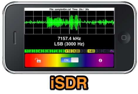 iSDR is a software defined radio application compatible with the Apple iPhone, iPod touch and iPad. iSDR is designed for experimenters, shortwave listeners, and amateur radio enthusiasts who would like a truly portable software-defined radio receiver.
 -
 Constructing a compact, directional antenna for the 6-meter band presents unique challenges, especially for operators with limited space or those seeking portable solutions. This project details the build of a 50 MHz Moxon rectangle, specifically engineered for balcony or temporary mast deployment, using readily available materials from a typical hardware store. The design emphasizes ease of construction and portability, allowing for quick setup and breakdown. The antenna's dimensions are precisely calculated using _Moxgen_ software for 50.200 MHz, ensuring optimal performance. Key construction techniques include using aluminum U-channel for elements, fiberglass driveway markers for insulation, and cable ties for secure assembly. The guide provides detailed instructions for fabricating the driven element, reflector, and boom, including a clever method for creating foldable element tips for transport. Performance observations indicate a respectable front-to-back ratio, capable of reducing an S7 signal to S0 when pointed away, and a modest gain over a simple wire antenna. The design incorporates a ferrite bead choke balun at the feedpoint to mitigate common-mode current and reduce shack noise, a critical consideration for urban or apartment-based operations.
 -
-
 The KD6WD Moxon Antenna Project details the construction of 50-ohm two-element wire beam antennas, specifically Moxon rectangles, for the 10, 15, 17, and 20-meter bands. It utilizes AC6LA's software for critical measurement calculations (A-E) based on center frequency and wire size. Construction involves 16-gauge silver-coated copper wire, 16-foot telescoping fiberglass crappie fishing poles as spreaders in an "X" configuration, and various hub designs including aluminum tubing or PVC joints. A 1:1 current balun is used at the feedpoint, with wire nuts for connections, often achieving a 1:1 SWR across the design band. The project highlights practical applications, such as running a kilowatt into the antennas for greyline DX contacts, consistently yielding excellent signal reports. Comparisons to quad loops show 4 to 5 S-unit improvements in both receive and transmit. The Moxon design, according to L.B. Cebik's analysis, offers superior forward gain and front-to-back ratio among wire beams. The author notes a "DX-Vane" effect where a freely suspended Moxon automatically points to the strongest DX signal. Attempts at dual-band operation (17/20 meters) with a single feed were unsuccessful, reinforcing the Moxon's monoband nature, with EZNEC plots provided for a 17-meter Moxon at 30 feet.
 -
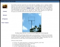
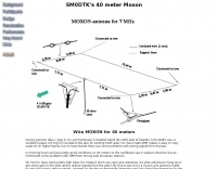 SM0DTK's 40-meter Moxon antenna project details the construction and deployment of a wire Moxon rectangle, specifically dimensioned for the 7 MHz band. The resource outlines the use of a _Moxon Rectangle Generator_ for calculating wire lengths and the fabrication of plexiglass supports for corners and the feeding point. It describes the practical challenges of elevating the antenna to approximately **14 meters** using an aluminum tube and fiberglass rod, emphasizing the adjustment process for achieving the correct rectangular shape. The article presents comparative results against a 60-meter long-wire and a full-size 40-meter ground plane antenna. The Moxon demonstrated significant directional gain towards the west, facilitating DX contacts in the Caribbean with **100 watts**, while simultaneously reducing QRM from strong eastern European stations. The SWR was reported as perfect without the need for an antenna tuner, validating the design's effectiveness for targeted signal enhancement and interference mitigation.
 -

-
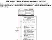 a Javascript for calculating the lengths of tubing to be used for the construction of a Super J-Pole.
 -
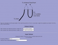 Online calculator for a 4 to 1 coax cable balun
 -
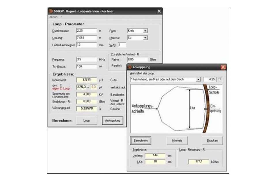 Magnetic loop antenna calculator and loop antenna design program for windows let you calculate dimensions for magnetic loops antennas, in german
 -
 Presents a practical approach to constructing a portable, lightweight antenna support structure, ideal for field operations or temporary installations. The design utilizes readily available PVC pipe sections, allowing for a total height of **20 feet** and a transportable weight of **25 lbs**. Detailed material lists specify various PVC pipe diameters and lengths, along with couplers, tees, and elbows, facilitating a modular assembly that can be easily disassembled for transport. Accompanying the tower design, the resource also outlines the construction of a _MicroVert_ antenna, including formulas for radiator length, capacitance, and inductance. It provides guidance on creating a current balun using ferrite beads or a coax coil, and calculating counterpoise length for optimal performance. The antenna section includes a schematic diagram illustrating the connection of the SO-239 connector and counterpoise.
 -
 Quagi antenna design, this little windows application let you calculate dimensions of elements and spacing of a quagi antenna. Freeware by VE3SQB
 -
 The resource details the construction and performance of a dual-band 40/30 meter _Moxon_ antenna, evolving from an initial single-band 30-meter design that failed in a storm. It specifies materials such as four 10-meter fishing rods, galvanized iron TV antenna support pipes, 1mm diameter PVC-covered copper wire, and a piece of 75-ohm TV satellite cable for feedline. The document outlines the iterative design process, including initial resonance measurements of 9.9 MHz for 30 meters and subsequent recalculations to shift the center frequency by 300 kHz using _Moxon software_. Initial testing on a roof yielded SWR readings of 1.4:1 at 7.200 MHz and 1.5:1 at 10.280 MHz. After installation atop a 30-meter tower, the final SWR measurements were 1.1 at 7.130 MHz and 1.4 at 10.230 MHz, with a notable 30 dB front-to-back ratio on 40 meters. The 30-meter performance, while good, showed a front-to-back ratio of approximately 15 dB, suggesting a slightly high resonance. The antenna's placement on a 700-meter hill, with a significant ground drop in certain directions, is noted as a potential factor in its excellent DX performance, enabling daily contacts with the USA West Coast on 30 and 40 meters with 100 watts.
 -
 F6EZX presents a detailed account of constructing a compact, multi-band _Levy antenna_ for portable holiday operations, specifically addressing issues with local QRM from a previous _Deltaloop_ setup. The article outlines the design criteria, including multi-band operation on 40m, 30m, 17m, 15m, 12m, and 10m, a symmetrical configuration to reduce interference, and a low take-off angle for DX. Construction involves 2x 10.3m radiating elements and a 15.3m open-wire feeder (ladder line) with 7cm spacing, made from 1.5mm2 copper wire and foam pipe insulation spacers. Theoretical calculations, referencing F9HJ's "_Les antennes Levy_" book, guide the determination of element lengths and feeder impedance characteristics, aiming for a good match across bands with a commercial antenna tuner. Initial field tests with the _VCI Vectronics VC300DLP_ tuner showed a 1:1 SWR from 80m to 10m, with some difficulty on 17m. The antenna, mounted as a 45-degree slopper with the high point at 12m, successfully facilitated DX contacts to South America, particularly Chile and Argentina, suggesting a lower take-off angle compared to the previous Deltaloop which favored Brazil. The Levy antenna significantly reduced TVI/RFI, attributed to its improved symmetry and greater distance from the QRA. While signal reports on 15m and 20m were 1-2 S-points lower than the Deltaloop, its performance on 40m and 30m was comparable, fulfilling the design goals for a portable, low-cost, multi-band solution.
 -
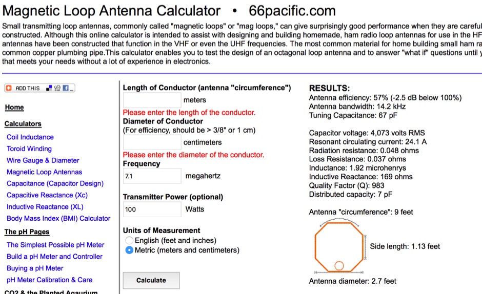 A free online calculator for making all of the calculations required to design and build small transmitting loop antennas, also known as magnetic loops by 66pacific.com
 -
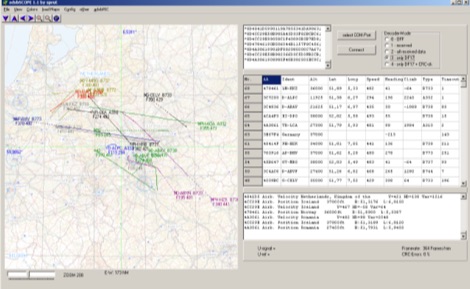 adsbScope is a freeware Windows application designed for processing _ADS-B_ (Automatic Dependent Surveillance-Broadcast) frames received from a compatible decoder. It identifies aircraft, calculates their real-time positions, and presents flight parameters in both alphanumeric tables and a graphical display. The software interfaces via a virtual COM port, receiving raw frames to provide detailed situational awareness, including a global coordinate grid, continental coastlines, over 4,000 **airport** locations, and major cities. Users can overlay OpenStreetMap tiles and view world state boundaries, with each tracked aircraft rendered with labels showing altitude, speed, heading, squawk code, and flight identifiers. When paired with the adsbPIC-decoder, adsbScope enables advanced hardware control, allowing users to toggle data filters for specific frames like DF17/18/19, adjust analog signal thresholds for reception fine-tuning, and manage system resets or bootloader activation directly from the PC. This functionality provides a customizable toolkit for hobbyist radar listeners, offering a robust alternative to commercial tools for processing aircraft data. The software displays up to **1090 MHz** transponder data and can track aircraft up to 250 nautical miles.
 -
-
 Log periodic antenna design excel sheet file download, in italian.
 -
 MoxGen is a **Windows** application designed to calculate dimensions and generate antenna model files for 50-ohm **Moxon Rectangle** antennas. Users input the desired design frequency in MHz and the wire size (AWG or diameter in inches/mm), and the software outputs the precise element lengths, spacing, and overall dimensions required for construction. It also creates a .maa file compatible with EZNEC, enabling further analysis and optimization of the antenna's performance characteristics. The software provides a visual representation of the Moxon rectangle, displaying key parameters such as gain, front-to-back ratio, and SWR at the design frequency. This allows radio amateurs to quickly assess the potential performance of their proposed antenna before physical construction. The generated EZNEC model facilitates detailed pattern analysis, impedance matching, and interaction with surrounding structures, proving useful for both initial design and fine-tuning.
 -
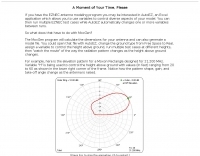
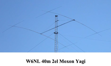 This resource presents a detailed analysis of the W6NL 2-element 40-meter **Moxon Yagi** antenna, covering its design, construction, and measured performance characteristics. It outlines key specifications such as a free-space gain of 6 dBi, 11 dBi at 70 feet, and a direct 50-ohm feed. The document highlights the antenna's physical attributes, including 52-foot elements, a 27-foot boom, and a weight of 75 pounds, engineered to withstand 125 mph winds. Modeling was performed using **AO6** and K6STI software, with a focus on the unique functions of the transverse tip elements for Moxon coupling, physical balance, efficient capacitive loading, and reduced wind load. The presentation includes comparative data, showing the Moxon's superior front-to-back (F/B) ratio and wider bandwidth compared to traditional loaded Yagis. Performance graphs illustrate the SWR, gain, and F/B across the entire 40-meter band (7.0-7.3 MHz), comparing measured results against calculated values. Azimuth and elevation patterns demonstrate high F/B, with the antenna's pattern matching that of a full-size 3-element Yagi on a 30-foot boom. It also notes a gain difference of 1.5 dB down relative to a K3LR 4-element Yagi on a 50-foot boom, providing practical benchmarks for performance evaluation.
 -
 This is my simple implementation of the ARRL Antenna Book design equations for the axial-mode helical antenna.
 -
 Inverted V antennas is a dipole with the center raised on a mast and the endpoints near ground. Calculate dimensions online.
 -
 End-Fed Half-Wave Antennas (EFHWAs) are analyzed for their utility in portable QRP operations, emphasizing their simplicity, efficiency, and predictable radiation patterns compared to other portable antenna types. The discussion contrasts EFHWAs with vertical antennas, random length wires, and center-fed dipoles, highlighting the common pitfalls of each, such as ground system dependency for verticals and feedline issues for dipoles. The article details the electrical half-wavelength calculation using the formula L (Ft) = 468/F(MHz) and explains how EFHWAs can be resonant on harmonic frequencies, enabling multiband operation. Various deployment configurations are presented, including the inverted L, inverted Vee, sloping wire, and vertical setups, each with specific advantages for radiation angle and polarization. For instance, a vertical EFHWA offers a low angle of radiation suitable for DX contacts without requiring an extensive ground system. The resource also addresses the counterpoise requirements, suggesting a quarter-wavelength wire or connection to a metallic structure for decoupling. A schematic diagram for a simple parallel-tuned circuit tuner, based on the _Rainbow Bridge/Tuner_ design, is provided, detailing component values for 30 and 40 meters, including a 6 microhenry toroidal inductor and a 20-100 picofarad mica compression capacitor. The tuner's adjustment process for SWR matching is also outlined.
 -
 PA3FWM's software defined radio (SDR) page documents his extensive hardware and software development efforts between 2004 and 2009. Initial experiments utilized a direct conversion receiver with 90-degree phase difference, feeding a PC soundcard at 48 kHz sample rate, covering 24 kHz of spectrum around a 7080.5 kHz local oscillator. This setup, similar to AC50G's QEX 2002 article, allowed for basic I/Q signal processing to distinguish signals above and below the LO frequency. Limitations included fixed crystal frequencies, 16-bit dynamic range, and narrow bandwidth. Subsequent hardware iterations aimed for enhanced performance, incorporating external 24-bit ADCs with 192 kHz sample rates, connected via 10 Mbit/s Ethernet. A **MC145170-based PLL** and programmable octave divider provided a 58 kHz to 30 MHz tuning range. The **Tayloe mixer** was employed, with differential outputs feeding a PCM1804 ADC. An ATmega32 microcontroller handled serial data conversion to Ethernet frames, though without CRC calculation due to processing constraints. Later designs integrated AD7760 2.5 Msamples/second ADCs and a Xilinx Spartan-3 FPGA, enabling direct reception of 0-1 MHz spectrum and eventually 2.5 MHz bandwidth across the shortwave spectrum. Software was refactored to use an initial 8192 non-windowed FFT for efficient high-bandwidth processing. The project culminated in a two-way QSO on 21 MHz using the developed hardware and software, demonstrating transmit capabilities with a D/A converter. The system exhibited a 2.5 MHz wide spectrum display and a zoomed 19 kHz display, capturing signals like ionospheric chirp sounders and RTTY contest activity. Challenges included noise leakage from digital circuitry and cooling for high-power dissipation components.
 -
 This PDF document, authored by KT4QW in October 2004, details the construction and modeling of a dual-band, horizontally polarized hanging rectangular loop antenna for **10 and 17 meters**. The design, adapted from *The ARRL Handbook*, utilizes _NEC4WIN95_ software for scaling and optimization, targeting a 50 ohm feedpoint impedance. The resource includes a bill of materials, step-by-step construction instructions, and a discussion of the antenna's radiation characteristics. It presents NEC-generated elevation and azimuth patterns, comparing the loop's performance to a half-wave horizontal dipole at the same height and frequency. The 17-meter element is centered at 18.140 MHz for low SWR across the phone band, while the 10-meter element is centered at 28.500 MHz. Construction involves 14-gauge stranded copper wire and Schedule 40 PVC spreaders, with the total wire length calculated by the formula: Length in feet = 1005/MHz. The feedpoint impedance can be adjusted by modifying the rectangular aspect ratio. The document specifies hoisting the antenna to at least a half-wave above ground for testing. It notes that a balun was tested and found to have no measurable effect on SWR or radiation characteristics. A 2-meter scale model is presented to illustrate the physical design, and a "rotator" string is incorporated for directional adjustment up to 90 degrees.
 -
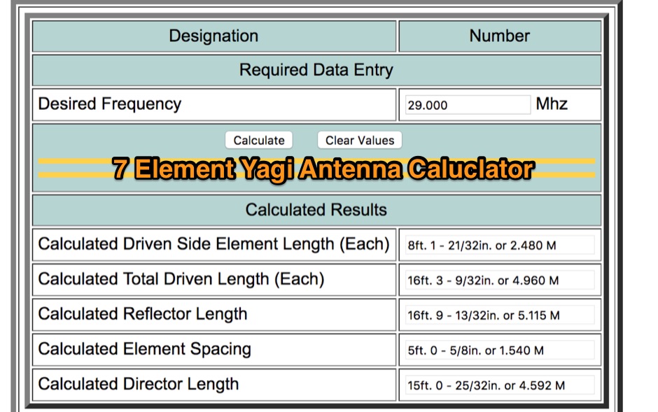 Online javascript antenna calculator designed to give the critical information of a particular beam antenna, in this case a seven element Yagi, for the frequency chosen.
 -
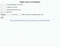
 This page lets you do calculations for single layer air cored coils using the solenoid formula
 -
 Calculates precise dimensions for **Moxon rectangle** HF antennas, enabling hams to design antennas by inputting desired resonant frequency and wire diameter. This web-based tool, version 0.5, is a PHP front-end developed by W4/VP9KF, based on a public domain BASIC program originally authored by L. B. Cebik, W4RNL. It generates critical measurements for the driven element and reflector, ensuring proper spacing and element lengths for optimal performance. User feedback confirms the calculator's accuracy, with one user reporting resonance within 50 Hz of the design frequency for an 18 MHz antenna, eliminating the need for SWR adjustments. This contrasts with other online tools that resulted in significant frequency discrepancies. The tool's precision facilitates building **directional antennas** for specific bands, contributing to effective DXing and contesting operations.
 -
 Manufacturer of Fibreglass Whip Antennas, Low and mediun Frequency, HF and VHF Antennas Specialized in the design and manufacturing of a full range of Beacon (MF), AM Broadcasting 540 - 1700 KHz, HF 1.7 to 30 MHz, VHF 30 to 156 MHz and UHF 200 to 500 MHz antennas.
 -
 Managing extensive amateur radio contact logs efficiently requires specialized software that integrates various operational aspects. Aether provides a macOS-native logging solution, designed from the ground up using Apple's Cocoa, to streamline QSO entry, organization, and retrieval for Mac users. It supports modern macOS technologies and offers an intuitive interface, aligning with the user experience expected on Apple platforms. The application includes features such as automatic dupe checking, which quickly identifies previous contacts with a station, and awards tracking, indicating if a new contact is needed for specific operating awards. Aether also integrates rig control via RS-232, automatically populating frequency, mode, and power data from supported Elecraft, Icom, Kenwood, Yaesu, and some TEN-TEC transceivers. This automation reduces manual entry errors and speeds up the logging process. Furthermore, Aether offers comprehensive QSL management, including synchronization with eQSL.cc and Logbook of The World, and the ability to print QSO detail and address labels for paper QSLs. It also incorporates automatic callbook lookup from sources like QRZ.com and HamQTH.com, and calculates distance and beam heading, with Google Maps integration for visualizing contact locations. Full ADIF and Cabrillo import/export capabilities ensure compatibility with other logging software and contest submission platforms.
 -
 Constructing a compact, two-band magnetic loop antenna for HF operation, especially from constrained locations like a balcony, presents unique challenges. OK1FOU's design, inspired by DJ3RW's 50 MHz loop, addresses these by employing an unusual side-fed configuration and placing the symmetric, two-section variable tuning capacitor at the bottom of the loop, directly connected to the coax shield. The article provides specific material recommendations, including two 1-meter wooden pales and about 3 meters of thick loudspeaker cable, noting the high current (60A at 100W) in the loop. Construction steps detail forming two turns with a 5 cm gap, using a GDO to pre-tune the open loop to a frequency slightly above the desired highest band, and then integrating the tuning and coupling capacitors. For 10/14 MHz, an open loop resonance of 16-17 MHz is suggested. Practical experience with the 10 MHz band from a third-floor balcony in Prague (JO70GC) shows a 1:1 SWR across most of the band without an external ATU. While DX traffic was modest due to the urban environment, QSO examples with RA6WF, LA6GIA, G0NXA, and LZ1QK on 10 MHz are provided, demonstrating its operational capability.
 -
 A circular waveguide calculator for designing cantennas include source code and windows executable by lincomatic
 -
 G4URH calculations to design your own antennas, ground plane, half wave antennas, Quad Antennas and 5/8 verticals
 -
 ERP Calculator is an Amateur Radio software utility designed to perform a side-by-side comparison of two Ham Radio antenna systems. ERP Calculator comes pre-programmed with data files including published data for several popular brands and types of coax cable as well as several popular antenna system brands and models. ERP Calculator displays values of ERP, Antenna Power Gain, Antenna Feed point Power, Antenna System Gain in dB, Antenna Gain in dBd, SWR Attenuation in dB, SWR Power Attenuation, Coax Loss in dB, and Coax Power Loss