Search results
Query: antenna measure
Links: 124 | Categories: 3
-
 Constructing a 5-element quad antenna, the author aimed for low cost and simplicity, resulting in an effective design with 11 dBi gain and SWR of 2:1 or better across the 2-meter band. Using wood and dowels, the antenna costs under $8 and takes less than two hours to build with basic tools. The model predicts excellent performance, confirmed by ARRL Lab measurements. Practical field results demonstrate improved communication, even in simplex mode.
 -
 Showcasing German engineering, ANjo Antennen develops and manufactures a diverse portfolio of amateur radio and commercial antenna products. Their offerings span a wide frequency range from 1.8 MHz to 3000 MHz, emphasizing electrical and mechanical precision for longevity. The company actively participates in events like FUNK.TAG Kassel, providing opportunities for direct engagement and order pickup. ANjo's product line includes high-performance **Yagi antennas** optimized for Tropo and EME, along with multi-stacked Quad antennas designed for contest operations, featuring wide horizontal and narrow vertical beamwidths. They also produce circularly polarized satellite antennas, some with switchable LHCP/RHCP, leveraging their commercial satellite antenna expertise. Beyond amateur applications, ANjo provides flexible, custom antenna solutions for commercial sectors such as BOS, EMC measurements, and telemetry. Their commitment to quality is evident in the Premium-Line antennas, which utilize **1.4301 (V2A) stainless steel** for mast clamps and connectors, ensuring durability and corrosion resistance. They also offer end-fed HF multiband wire antennas, known for their compact footprint and discreet installation.
 -
 Method, Units of Measure, and the Dipole Standard of Reference. This article helps in understanding where does beam gain come from in directional aerials like in example Yagi antennas.
 -
 This blog post by VE3VN discusses the design and performance of a 40-meter reversible Moxon antenna. The antenna provides coverage between southeast to west by default, with the ability to reverse for coverage from east to northwest. The post explains how the antenna performs well in various directions, focusing on the Caribbean, South/Central America, the US, and Europe. Detailed measurements and design considerations are shared, highlighting the accuracy of the model and the critical importance of coil inductance. The post also mentions the use of NEC5 for accurate modeling. Overall, this detailed discussion provides valuable insights for ham radio operators looking to optimize their antenna setup.
 -
 The Dipole Bazooka Antenna for 40 meters is a popular choice among amateur radio operators. Its design allows for easy construction using materials like RG58 coaxial cable and PVC. Measurements are calculated using specific formulas; for instance, at a frequency of 7,100 MHz, the total length is approximately 19.74 meters. This antenna offers a performance range of 97% to 99%, with an impedance of 49 to 52 ohms. Additionally, it can handle up to 1 kW of power and requires no modifications for connection.
 -
 This article published on QEX details measurements of tree conductivity and permittivity at HF frequencies, addressing a long-debated topic in amateur radio. N6LF conducted experimental impedance measurements on Douglas fir and maple trees using a vector network analyzer with rings of nails inserted into tree trunks. Results showed that tree conductivity increases with frequency while relative permittivity decreases, similar to soil characteristics. Measured conductivity ranged from 0.06 to 0.4 S/m at 10 MHz, aligning with values used in previous research. These findings validate that NEC modeling can reliably estimate trees' substantial impact on HF antenna performance.
 -
 Chavdar Levkov, LZ1AQ, presents an experimental comparison of small wideband magnetic loops, building on his previous work on wideband active small magnetic loop antennas. His research focuses on increasing loop sensitivity by maximizing the short-circuit current, which is directly tied to the "loop factor" M = A/L, where A is the equivalent loop area and L is its inductance. Levkov's methodology involves reducing inductance and increasing area through parallel or coplanar crossed (CC) configurations, comparing these designs against a reference single quad loop of 1 m2 area. Experimental verification included testing three distinct loop types: a simple quad loop, two coplanar crossed (CC) loops, and eight parallel loops, all designed to have a total geometric area of 1 m2. Measurements were conducted at 1.8, 3.5, 7, and 10 MHz using a small transmitter 270 meters away, with a Perseus direct sampling receiver for precise signal level assessment. The results consistently showed that CC loops, particularly Loop 5 (two CC circular loops with 1.44 m2 total area), yielded significantly higher currents, up to 9.1 dB over the reference loop at 3.5 MHz, validating M as a reliable predictor of loop sensitivity. Numerical simulations using MMANA further corroborated the experimental findings, demonstrating an almost perfect correlation between the calculated M factor and the induced loop current for 15 different loop models. Levkov concludes that CC loops offer superior sensitivity for a given loop area, while parallel loops are advantageous for minimizing physical volume. Practical recommendations suggest using loops with an M factor greater than 0.5 uA/pT for quiet rural environments, and he provides a spreadsheet tool, WLoop_calc.xls, to aid in optimizing loop configurations for specific operational needs.
 -
 Effective suppression of harmonics and parasitic radiation from HF transmitters is crucial, especially with the increasing sensitivity of VHF/UHF radio channels to interference. This project details a hybrid low-pass filter (LPF) designed to operate across the HF bands up to 51 MHz, making it suitable for 6-meter band operations while providing deep VHF/UHF suppression. The design addresses the challenge of modern interference landscapes, where even microvolt-level signals can disrupt wireless sensors and other simple VHF/UHF receivers. The filter utilizes a single elliptic link, combining high cutoff steepness with robust suppression in the hundreds of megahertz range. A key feature is the use of only two standard capacitor values, simplifying construction and component sourcing. The article provides a detailed schematic, performance characteristics, and _RFSim99_ model file, demonstrating a reflection coefficient S11 below 0.017 (VSWR < 1.03) across 1-51 MHz, ensuring minimal degradation to the antenna system. Construction notes include coil winding specifications and capacitor selection guidance, with recommendations for _FR-4_ assembly. Two capacitor sets are presented, with the first variant recommended for its lower RF current demands, keeping currents below 3 A at 1 kW passing power at 51 MHz. Fine-tuning involves adjusting frameless coils, with considerations for capacitor tolerance and high-frequency capacitance measurement accuracy.
 -
 The F6AOJ RX splitter project was created to split the antenna signal from an LZ1AQ receive loop to multiple receivers, such as radios or SDRs. The design is simple to build and effective. The splitter, mounted on the back of the LZ1AQ control board, provides two outputs—one for an Afedri SDR and another for a K3 transceiver. Measurements show a damping of -3.01 dB at 1 MHz and -3.10 dB at 30 MHz, with a low SWR (max 1.07 at 30 MHz and 1.4 at 60 MHz).
 -
 Testing of real antennas is fundamental to antenna theory. The most common and desired measurements are the antenna radiation pattern including antenna gain and efficiency, the impedance or VSWR, the bandwidth, and the polarization. The procedures and equipment used in antenna measurements are described in this page.
 -
 The tri-band trapped delta loop antenna design operates on 80 meters (3.5–4 MHz), 40 meters (7–7.3 MHz), and 30 meters (10.1–10.15 MHz) using a single triangular wire loop. This configuration eliminates the need for an external antenna tuner or band-switching relays. The antenna's physical perimeter, approximately 270 feet, establishes 80M as the fundamental band, with specific trap placements enabling resonance on 40M and 30M. Trap design and placement are critical, with 30M traps positioned inboard of 40M traps within the horizontal element. Each slant leg measures approximately 80 feet. The resource references foundational information from the _ARRL Antenna Handbook_ and _ON4UN’s Low Band DXing_ regarding full-wave loop behavior and feedpoint impedances. The project aims to provide multi-band HF operation from a single, fixed antenna structure.
 -
 Delta loop antennas, particularly the 30 meter variant, offer unique advantages in terms of vertical polarization and omni-directional coverage. The construction process detailed by VE3VN highlights common mechanical and electrical challenges faced by amateur radio operators. Key design considerations include minimizing interaction with existing contest band antennas, achieving low elevation angles for DX chasing, and ensuring the antenna remains off the ground for agricultural clearance. The article provides specific measurements, such as the loop's height and feed point impedance, which are critical for optimizing performance. The use of NEC modeling software illustrates the importance of accurate resonance calculations, revealing how proximity to the tower affects both pattern and impedance. This practical account serves as a resource for hams looking to build effective antennas while navigating typical construction hurdles.
 -
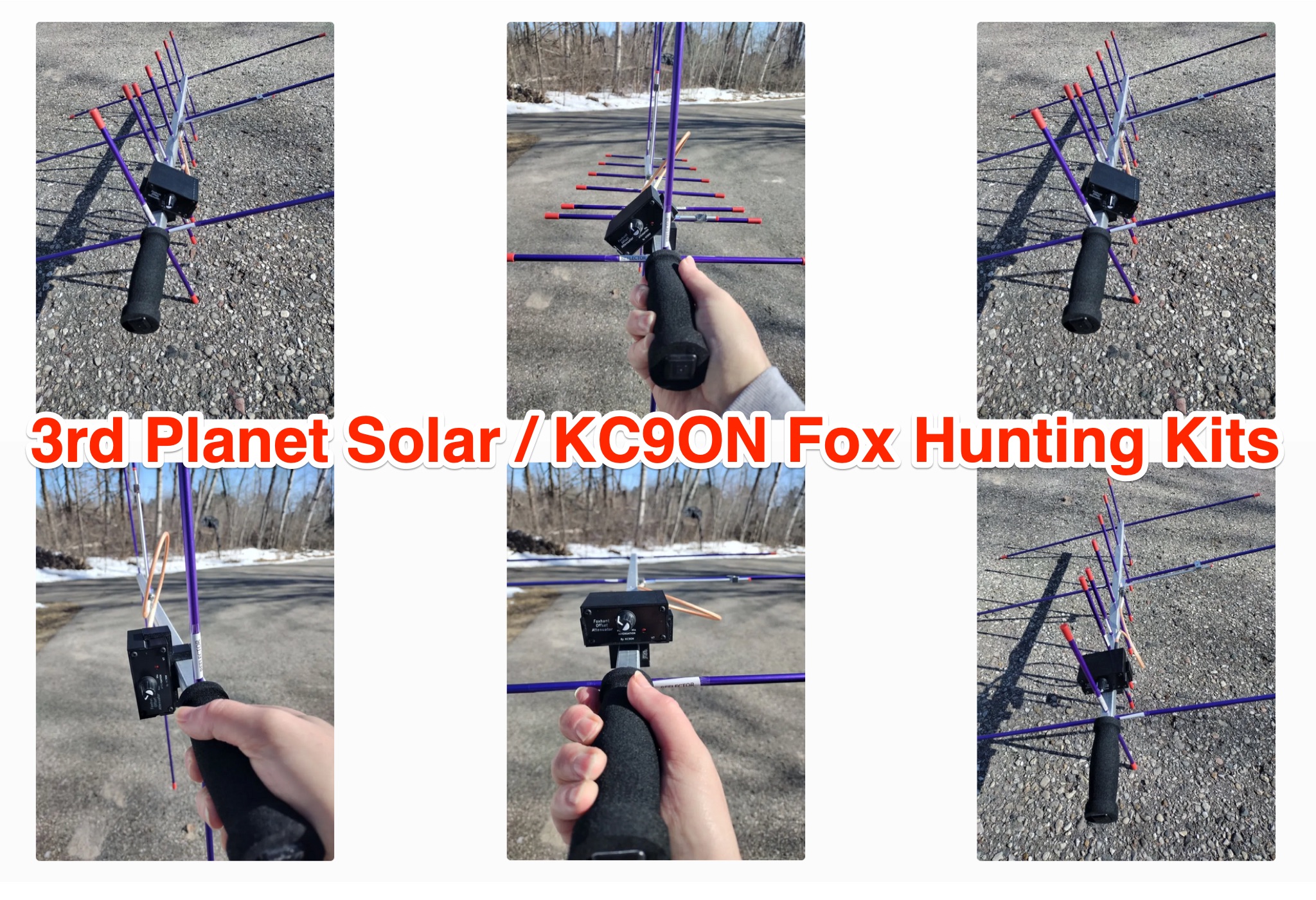 Explore the world of fox hunting with the Fox Hunt V7 Kits and Assembled Units. Learn about the different antennas used for fox hunting, such as the tape measure beam with an offset attenuator. Discover how to make your own WB2HOL beam antenna using PVC pipe, T's, and a tape measure. Find out how the offset attenuator works and how it can help you track down jammers and interference. Whether you're a seasoned fox hunter or just starting out, this page offers valuable insights and tips for improving your hunting skills.
 -
 This page provides basic information about SWR (Standing Wave Ratio) and its importance for ham radio operators. It explains what SWR is, how to measure it, and why it is crucial to have a good SWR reading. The content covers the impact of SWR on antenna efficiency, power transmission, and potential interference issues. It clarifies common misconceptions like the impact of coax length on SWR. Suitable for hams looking to optimize their radio setup and avoid performance issues due to SWR issues.
 -
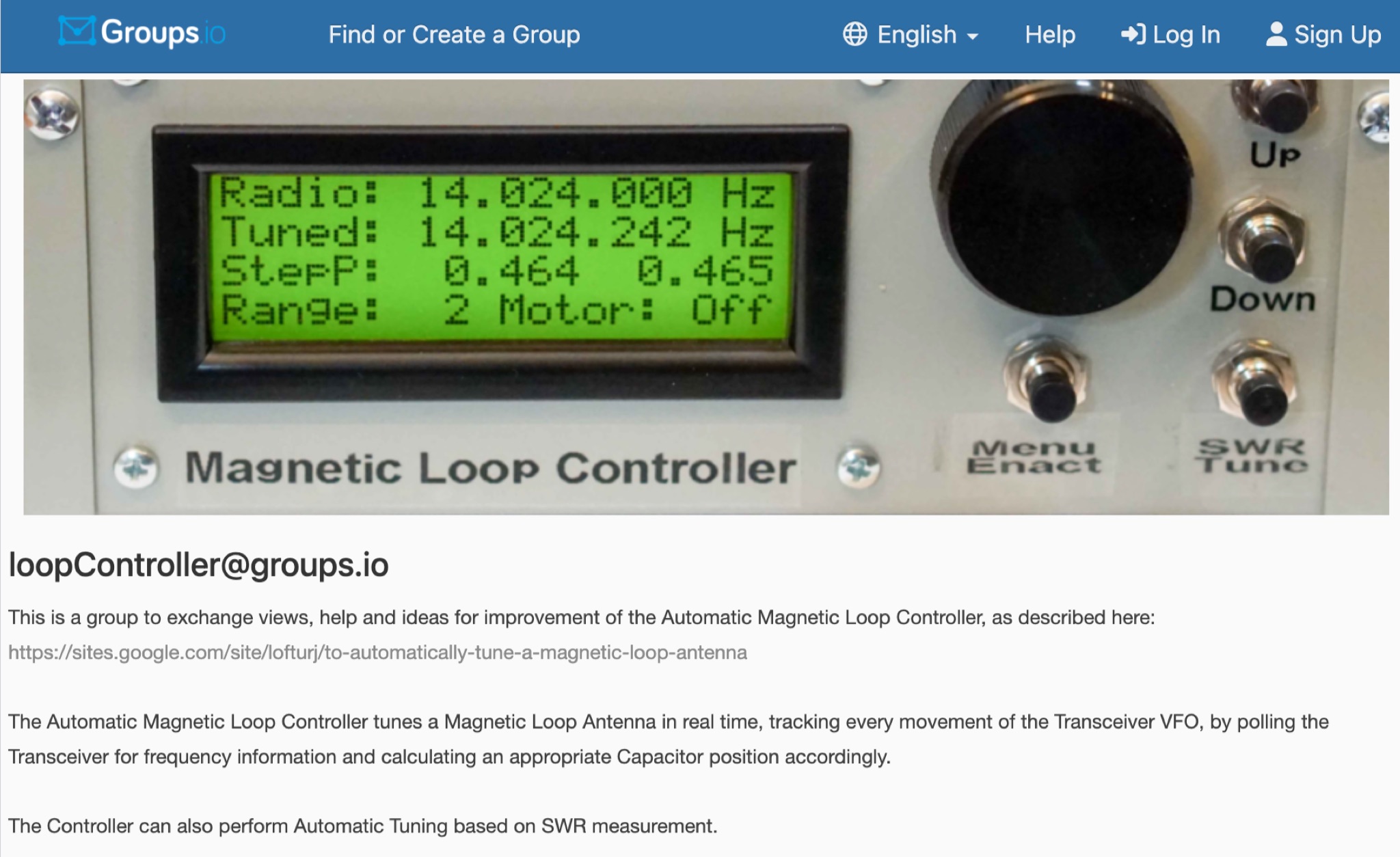 This is a group to exchange views, help and ideas for improvement of the Automatic Magnetic Loop Controller, as described at VE2AO web site. The Automatic Magnetic Loop Controller tunes a Magnetic Loop Antenna in real time, tracking every movement of the Transceiver VFO, by polling the Transceiver for frequency information and calculating an appropriate Capacitor position accordingly. The Controller can also perform Automatic Tuning based on SWR measurement.
 -
 Guide to constructing an effective antenna for 50MHz. Inspired by a design from Martin DK7ZB, the article emphasizes the importance of precise measurements and quality materials. With a 2.20m boom and careful assembly, the antenna promises excellent performance, resilience, and cost-effectiveness, making it ideal for six meter band operations.
 -
 This comprehensive article dispels common misconceptions about Standing Wave Ratio (SWR) in amateur radio. The author explains that SWR is not an antenna property but a measure of the entire antenna system, representing the mismatch between transmission line and load impedance. Contrary to popular belief, modest SWR values (under 3:1) typically cause minimal power loss in HF applications. The article demonstrates mathematically why obsession with achieving 1:1 SWR is often unnecessary, explains when SWR matters more (QRO, QRP, VHF/UHF), and explores effective matching techniques including proper ATU placement and quarter-wavelength transformers.
 -
 VE1ZAC's analysis details the performance of **MFJ927** and **SGC239** autotuners with portable HF vertical antennas, specifically comparing 31 ft and 43 ft configurations. The resource originated from challenges encountered during a Maritime QSO Party roving operation, necessitating a lightweight and easily deployable antenna system. Target bands for the contest included 80, 40, 20, 15, and 10 meters, with a maximum power handling of 100 W CW. The author utilized a 30-foot carbon fiber push-up pole to support a vertical wire element, noting its 2 lb weight and reliability. EZNEC modeling was employed to predict performance, showing favorable results for a 30-foot vertical with elevated radials, particularly on 40 and 20 meters. Feedpoint impedance measurements, taken with an AIM4170C, are presented for various HF bands, both with and without a 41-foot RG6 stub designed to reduce reactance on 80 and 20 meters. The stub significantly improved matching on these bands, easing the tuner's workload. Operational tests revealed issues with the MFJ927's reliability during contest setup, leading to reliance on the K3's internal tuner. The SGC239, tested post-contest, performed flawlessly. A detailed side-by-side comparison covers mechanical aspects, connection options, power bias, impedance range, board quality, and documentation. Modifications to the MFJ927, including a new aluminum case, white paint for heat reduction, and upgraded impedance-measuring resistors, are also described.
 -
 Twenty 1-watt carbon film resistors are configured in parallel to construct a 50-ohm **dummy load** for amateur radio applications. The design incorporates a heatsink for thermal dissipation and an **SO-239 connector** for RF input, making it suitable for QRP operations. This budget-friendly project details component selection, soldering techniques, and mounting procedures, achieving a continuous power rating of 10 watts and intermittent handling of up to 100 watts across HF and VHF frequency ranges. The resource provides a step-by-step guide for assembly. This construction offers an economical solution for essential shack tasks such as antenna tuning, transmitter testing, and SWR meter calibration without radiating an RF signal. The utilization of readily available components significantly reduces the overall build cost compared to commercial alternatives, providing radio amateurs with a functional and reliable test accessory. While specific VSWR measurements are not provided, the design prioritizes practical utility for low-power transceiver diagnostics and general RF experimentation.
 -
 This resource presents a non-rigorous evaluation of the front-to-back (F/B) ratio of short Beverage antennas, specifically designed for low-band operation on frequencies such as 160, 80, 40, and 30 meters. The author, VE1ZAC, details the methodology used to measure the F/B ratio, which involves using a Millen Grid Dip Oscillator as a portable signal source. Measurements were taken by switching the antenna direction and recording S Meter and preamp readings to derive gain numbers. The document discusses the challenges faced in achieving accurate measurements and the assumptions made during the process, such as the calibration of S Meter units at 6 dB. This evaluation is particularly relevant for amateur radio operators interested in antenna performance on low bands.
 -
 This article describes a DIY RF field strength meter project inspired by VK3YE's "The Squeakie" design. The device, built around a 555 timer IC and a 1N4148 diode, converts RF signal strength into audible tones with proportional pitch. The author enhanced the original design by adding volume control, LED indication, and digital readout capabilities using an Arduino Nano and LCD display. The completed project functions as a versatile RF detection tool, suitable for antenna testing and fox hunting, while offering multiple output methods: audio, visual, and digital measurement display.
 -
 This study analyzes the antenna pattern of the Utah Amateur Radio Club's 146.760 MHz repeater following antenna relocation in 1997. Noting degraded transmission toward the north, a customized signal mapping system using a Yaesu FT-817, GPS, and software was developed to log real-time signal data. Calibration techniques extended the radio's signal range, enabling precise field measurements. The method allowed continuous signal strength monitoring while driving, revealing anomalies in coverage likely due to tower modifications. Findings helped assess and visualize the antenna’s actual radiation pattern and highlighted environmental impact on signal distribution.
 -
 Demonstrates the construction of an active loop converter specifically designed for the Low Frequency (LF) bands, addressing common localized noise interference in LF reception. The design integrates a sharply tuned circuit and a tuned loop antenna, utilizing the loop as the sole tuned inductive element. By applying positive feedback, the converter significantly increases the loop's effective Q, achieving factors between 1000 and 2000, which sharpens tuning and reduces noise. The circuit employs an _NE602_ mixer stage, feeding its output to an HF receiver, with a crystal-locked local oscillator at 4 MHz. A 20-turn, 0.8-meter square loop antenna with 500 uH inductance is detailed, connected via 2 meters of figure 8 flex cable. The converter offers three selectable frequency bands: 195-490 kHz, 150-220 kHz (including the New Zealand amateur band), and 128-160 kHz (covering the European amateur band). Performance measurements indicate an effective 3dB bandwidth of approximately 100 to 200 hertz at 200 kHz. The article provides insights into component selection, including an _LF353_ op-amp and a trifilar wound transformer on a ferrite core. Sensitivity figures are presented, showing 7.5 uV of converted output per 1 uV/meter signal strength into a 50-ohm load, or 37.5 uV into an _FRG7_ receiver, highlighting its capability to extract weak signals from noise.
 -
 The W6PQL 23cm Beacon Project describes a **1296 MHz** beacon designed for microwave propagation studies and equipment testing, capable of 30 watts output. It utilizes a PIC 16F628A microcontroller to generate CW and FSK keying for a crystal oscillator, followed by a series of frequency doublers and triplers to reach the target frequency. The final power amplification stage employs a Mitsubishi M57762 module, providing a robust 10-watt RF output. The design emphasizes stability and reliability for continuous operation, with the microcontroller code, written in assembly, provided for customization of the beacon's callsign and message. Originally located in CM97am and aimed at 140 true, the beacon used four 4-foot Yagis stacked vertically for a total ERP of 3kW. The article includes schematics, parts lists, and construction notes to guide builders, along with antenna pattern measurements. Although the beacon itself is no longer in service as of August 2010, the detailed documentation remains a valuable reference for amateur radio operators interested in building similar **microwave** projects or understanding beacon operation.