Search results
Query: eme antenna
Links: 743 | Categories: 9
Categories
- Antennas > 6M > 6 meter Yagi Antennas
- Antennas > Antenna Books
- Software > EME
- Radio Equipment > HF YAGI Antennas > Hy-Gain TH3JR
- Technical Reference > Lightning Protection
- Operating Modes > WiFi > Long Range WiFi
- Antennas > Maria Maluca
- Antennas > Feed Lines > Open Wire
- Technical Reference > Standing Wave Ratio
-
 The ZS6BKW multi-band antenna, an optimized variant of the classic G5RV, is presented with detailed construction and tuning instructions. This resource outlines the antenna's design principles, which were developed by _Brian Austin (G0GSF)_ using computer programs and Smith charts to achieve optimal dimensions. It provides specific guidance on calculating and adjusting the lengths of the radiators (L1) and the matching ladder line (L2), emphasizing the critical role of velocity factor (VF) in achieving resonance. The article includes a step-by-step procedure for empirically determining the VF of ladder line using an antenna analyzer, ensuring accurate physical lengths for the matching section. It details the tuning process for the radiators, offering practical tips for incremental adjustments to achieve the best SWR curve. The resource presents SWR measurement results obtained with an _AIM-4170C_ analyzer across multiple bands, alongside predicted SWR graphs from an AutoEZ model. It confirms successful contacts on 80, 40, 20, and 17 meters, including a **17-meter DX contact** to Italy. EZNEC and AutoEZ models for the ZS6BKW antenna, covering 80 through 6 meters, are provided for download, allowing further analysis and customization. The document specifies component details, such as the use of Wireman 554 ladder line and #14 AWG THHN copper wire, and discusses the antenna's performance characteristics, noting high SWR on 15 and 30 meters but successful tuning on 6 and 80 meters with an external tuner.
 -
 EF0603S is a 3 element portable yagi antenna for six meters band by YU7EF
 -
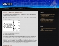 The Double 5/8 is a natural extension of the Single 5/8 and uses a 5/8λ element for both the top and bottom radiators.
 -
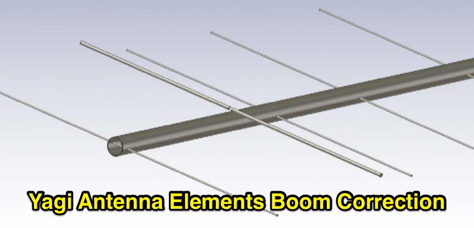 Dragoslav Dobricic, YU1AW antennex article on influence of Boom on frequency performance and how compensate it
 -
 Ground Plane - 1/4 wave vertical, J-Pole, 3 Element Yagi Beam and simple antenna supports
 -
 In this PDF article Zack Lau describe how to homebrew a four element yagi beam antenna for 50 MHz band, including how to build mounting blocks and tubing clamps to hold elements.
 -
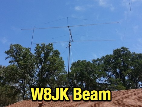 A compact 2 element W8JK beam antenna for 20M to 10M bands by AF6SA
 -
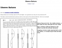 Sleeve baluns are normally used at VHF and higher. As a general rule, they are not practical at HF. The balun can be inverted and used as a skirt to form part of the antenna element
 -
 The GM4JJJ VHF and EME pages document David's extensive work in Earth-Moon-Earth (EME) communication, specifically on the 144 MHz band, and his involvement in amateur radio astronomy. The resource details his station setup and operational experiences, providing insights into the technical challenges and rewards of bouncing signals off the moon. It offers a glimpse into the specialized equipment and techniques required for successful EME contacts, a niche but highly rewarding aspect of amateur radio. David's content shares practical applications and field results from his EME endeavors, which can be particularly useful for hams contemplating or actively pursuing moonbounce operations. The information, while not a step-by-step guide, implicitly compares the complexities of EME with more conventional VHF/UHF operations, highlighting the significant power and antenna gain necessary to overcome path losses. This resource serves as a testament to the advanced capabilities achievable in amateur radio.
 -
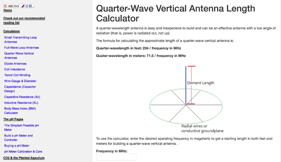 Use this online calculator to determine the length of a quarter-wave antenna from the frequency. Both metric and English units of measurement are supported.
 -
 Demonstrates various practical amateur radio projects and technical discussions through video episodes. One episode details cutting and retuning a _1/4 wave shorted stub_ from 101.7 MHz to 107.5 MHz to safeguard a transmitter's driver stage, alongside insights into advanced _160-meter antenna systems_ like eight-circle arrays and beverage antennas. Another segment covers upgrading firmware on an _ATS-20+_ receiver using AverDudes for improved display and functionality, and a detailed guide on using D-Star DR mode on an _ICOM ID-52A_ for international repeater programming. Additional content includes a deep dive into _OpenHamClock_ as a potential replacement for the HamClock project, updates on _Raspberry Pi 5_ running Trixie OS, and a review of the Choyong LC90 Internet radio with AI integration. The series also features "Ham College" episodes, which meticulously prepare viewers for the Technician Exam by covering topics such as antenna and transmission line measurements, SWR interpretation, and the functions of basic electronic components like rectifiers, relays, and transistors. Practical advice on coaxial cable characteristics, dummy loads, and proper soldering techniques is also provided.
 -
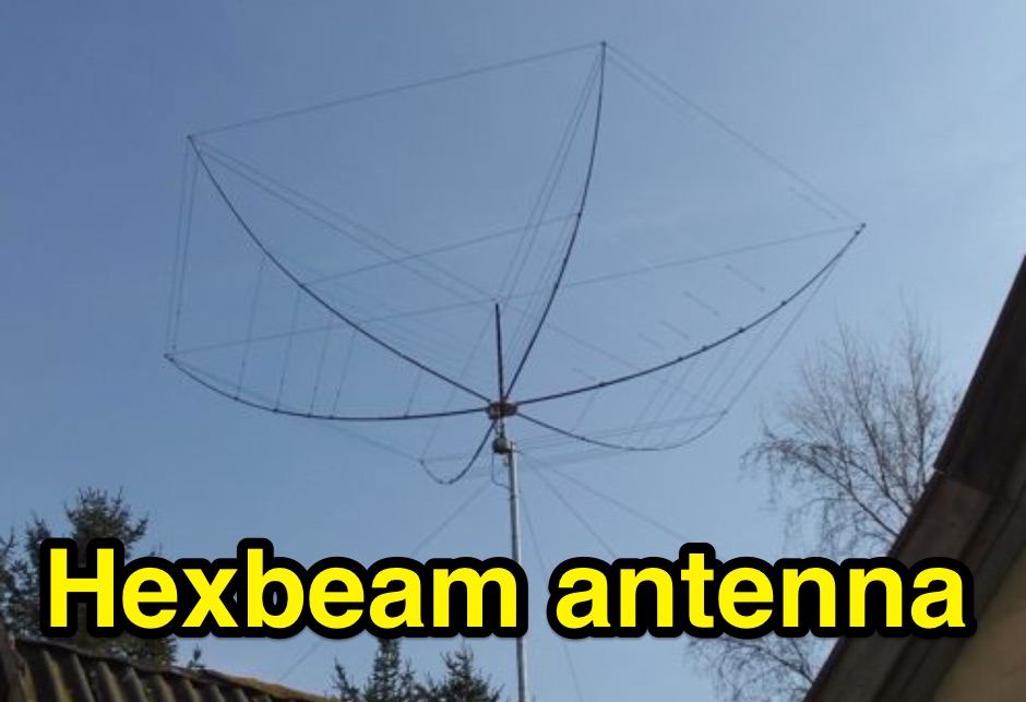 An HexBeam antenna project, a 2 full elements on six bands
 -
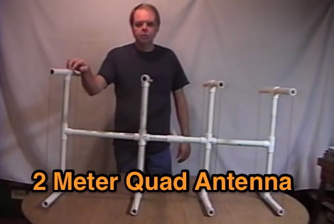 A four elements quad antenna for 144 MHz made with PVC pipes
 -
 The electrical characteristics of an antenna that are of interest to obtain by direct measurement are the frequency at which the antenna is tuned, the gain and radiation pattern
 -
 Dimensions and EZNEC plots for a 2 Element 30 meter Yagi antenna with 28 Ohm featuring 4.3 dBd Gain and a 16dB F/B with a good bandwidth.
 -
 Demonstrates the operational status and reception reports for the SK6RUD/SA6RR QRPP beacons, which transmit on 478.9 kHz, 1995 kHz, 10.131 MHz, and 40.673 MHz. These beacons utilize extremely low power, with the 630-meter beacon operating at approximately 0.1 watt ERP into an L-antenna, showcasing the potential for long-distance contacts under favorable propagation conditions. The site details the specific frequencies and antenna types employed, such as a vertical at 500 kHz and a 1/4 vertical for higher bands. The resource compiles over 10,530 reception reports from amateur radio operators worldwide, logging details such as date, time, band, RST signal report, locator, distance, and receiver setup. Notable long-distance reports include a 500 kHz reception by AA1A-Dave from 5832 km in 2008 and a 10.133 MHz reception by ZL2FT-Jason from 17680 km in 2010, illustrating the global reach of these low-power transmissions. Each log entry provides specific equipment used by the reporting station, including transceivers like the Yaesu FT817, ICOM IC-7300, and various antenna configurations such as coaxial mag loops, inverted Ls, and end-fed wires. The primary objective of the SK6RUD beacons is to challenge conventional notions of power requirements for effective two-way communication, proving that contacts over significant distances are achievable with minimal output. The site also includes a submission form for new reception reports, fostering community engagement and continuous data collection on propagation phenomena across different bands. The detailed logs offer practical insights into real-world propagation characteristics and the efficacy of QRPP operations.
 -
 A 5 element yagi beam antenna for ten meters band with full dimentsions, eznec file and coax match informations for 50 ohms feed line
 -
 Use this online calculator to determine the length of a full-wave loop antenna from the frequency. Both metric and English units of measurement are supported. Quarter-wave matching section lengths are also calculated.
 -
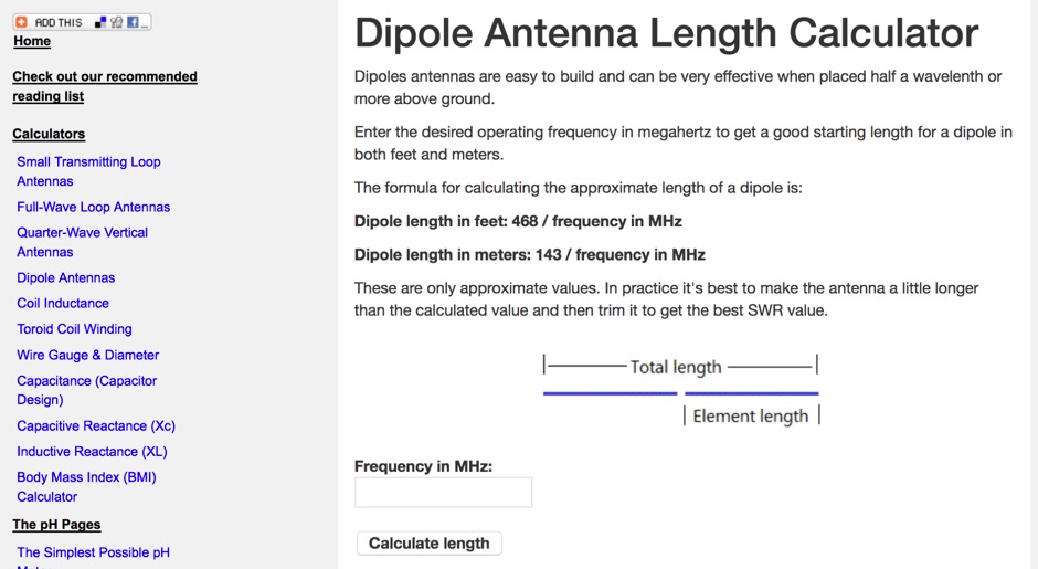 Use this online calculator to determine the length of a dipole antenna from the frequency. Both metric and English units of measurement are supported.
 -
 An homebrew project for a 4 elements yagi monoband antenna for the 10 meters by 9M2MSO
 -
 This web article by VK3BLG details the construction of an experimental 70cm (432 MHz) circularly polarized patch antenna, intended for satellite communication. The resource provides dimensions, feed point specifications, and impedance matching considerations for a single patch element, with discussion extending to array configurations for circular polarization. Construction involves a copper patch element on a dielectric substrate, fed via a coaxial cable. The design is based on information derived from AO-40 satellite antenna specifications, focusing on achieving circular polarization for satellite reception. The article includes specific dimensions for the patch and feed points, along with impedance values. Validation is implied through on-air satellite reception reports, with initial signal reports of **1 S-point above noise** for AO-40 beacons using a grid reflector, improving to **3-4 S-points above noise** with a 2-turn helical feed. The author references a _NanoVNA_ for impedance measurements and discusses the relationship between slot and dipole antennas in the context of patch design. DXZone Focus: Web Article | 70cm Patch Antenna | On-Air Satellite Reception | Circular Polarization
 -
 Examining the _Angle of Radiation_ and its impact on amateur radio operations, the resource provides insights into optimizing antenna performance for DX and local contacts. It features a design for SPOTTO, a direct conversion high-performance universal DSB transceiver, detailing its construction and operational characteristics for homebrew enthusiasts. Additionally, the site presents a 7-element VHF high-gain antenna design, offering practical schematics and expected performance metrics for those seeking enhanced gain on VHF bands. The resource also covers the development and popularity of the _FT8_ digital mode, highlighting its effectiveness in weak-signal conditions and its role in special event operations like the FT8DMC anniversary. It includes information on Hamfest India 2023 and the Lamakaan Amateur Radio Convention, providing dates and organizational details for significant Indian amateur radio gatherings. Technical articles on Direct Digital Synthesizers (DDS) VFOs and low-cost multifunctional frequency counters offer practical project ideas for radio amateurs.
 -
 An high gain long yagi antenna, seven elements, for six meters band
 -
-
 Antenna for limited space, made from 24AWG wire helically wrapped around the top element of a 3-element cane pole, is basically a fully-loaded vertical and performance are limited and should represent the last resort for extreme cases.
 -
 Article by G4AON about a 4 and 2 Element Quad Antennas for the 6m band
 -
 Millimeterwave/Microwave transmission lines and components, Cryogenic temperature application transmission cables and systems, Permittivity(Dielectric rate) and Permeabillity measurement systems, Antennas, Radar systems
 -
 A 2 element 40 meters band parasitic delta loop antenna project with pictures and details
 -
 Designing and constructing portable wire antennas for HF operations, this resource explores several configurations including the _foldback dipole_ for space-constrained setups and an inductively shortened dual-band dipole for 20m and 40m. It details the calculation of inductance for shortened elements, providing a Visual Basic 6.0 program screenshot that illustrates determining coil parameters like turns and length for a **25.5 uH** inductor. The document emphasizes practical considerations such as adjusting wire lengths for optimal SWR, noting that a dual-band dipole achieved SWR below 2:1 on both 20m and 40m, with careful adjustment bringing it under 1.5:1. Further, the resource describes a half-wave antenna matched with a coaxial stub, a method often referred to as the _Fuchskreis_ in German amateur radio circles, to transform the high feedpoint impedance to 50 Ohms. This monoband solution, for a 20m application, uses a stub length of **2.98m** (0.216 lambda multiplied by coax velocity factor) and a shorted stub of approximately 48cm. The coaxial stub design is highlighted for its resilience to ground proximity, allowing it to be rolled up or laid on the ground with minimal SWR impact, making it highly suitable for portable QRP operations.
 -
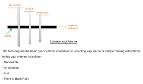 This article includes an online calculator for a 3 element Yagi Antenna. The formula and basics theory of Yagi Antenna are also explained with examples.
 -
 Antenna tuners are crucial for matching the impedance of antennas to the 50 ohm output impedance of transmitters. The _LDG Z-11 Pro_ is an automatic antenna tuner designed to handle up to 125 watts, making it suitable for a wide range of amateur radio applications. Its compact form factor allows it to pair well with transceivers like the _FT-857D_, providing a portable solution for operators who frequently change locations or setups. The tuner covers the 80 through 6 meter bands, offering a broad impedance match capability. Although it struggles with some loads, it performs well with typical ham antennas, even managing to load an 80 meter dipole on 6 meters. One of the standout features of the _Z-11 Pro_ is its 8000 memory slots, which enable it to remember successful matches and quickly retune when revisiting frequencies. This memory function significantly reduces tuning time, often to less than half a second. The unit is well-constructed, with improved pushbuttons and a sturdy metal case that offers good shielding. However, users should be aware of potential RFI issues and the lack of a power switch, which requires disconnecting the power cord to turn off the unit completely. Overall, the _LDG Z-11 Pro_ is a user-friendly and cost-effective tuner, offering advanced features that enhance its utility in various amateur radio setups.
 -
 Photo construction manual of a portable antenna made with two heavy duty whips by buddipole. In this article has been implemented a 50 MHz portable dipole.
 -
 The page discusses the concept of a 2-element Parasitic Ground Plane antenna for the 40-meter band. It includes a conversation between amateur radio operators discussing modeling results and design considerations for the antenna. The author shares insights on radial configurations and the impact on antenna efficiency and pattern.
 -
 Tips on winding wire coils used as inductive loads, traps, band-pass filters, are implemented in a number of amateur radio projects especially antenna projects
 -
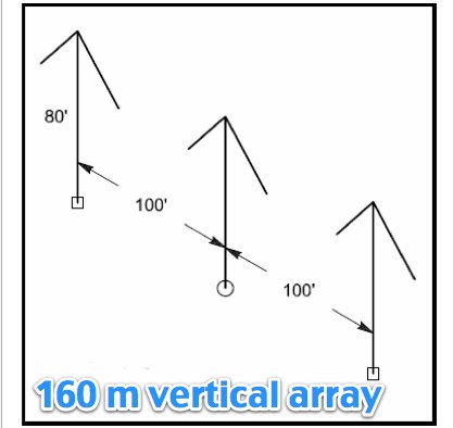 Article by N6LF on a top band vertical antenna array system
 -
 With the view to establish a quick and easy multi-band antenna deployment for portable and camping operations a simple long wire antenna with an earth or earth plus counterpoise arrangement with a 9:1 voltage unun including a tuner or simply with a tuner is one possible solution. With the 9:1 voltage unun and wire lengths suggested in the below tables the antenna should present non extreme impedances for all HF amateur band frequencies. This page is far from complete and represents the ongoing investigation into this type of antenna. Experiments to date seem to have raised more questions than obvious answers.
 -
 The early 20th century saw significant advancements in wireless communication, culminating in the first successful transatlantic radio signal. This historical account details Guglielmo Marconi's pioneering efforts, from his initial experiments with electromagnetic waves to his patented wireless system in 1900. It describes the technical challenges of long-distance radio transmission, particularly the prevailing belief that radio waves would be lost due to the Earth's curvature over vast distances. On December 12, 1901, Marconi established a receiving station in Newfoundland, Canada, utilizing a _coherer_ and balloons to elevate the antenna. Signals, consisting of the Morse code letter "S" (pip-pip-pip), were transmitted from Poldhu, Cornwall, England. The successful reception of these faint but distinct signals across **1,700 miles** confirmed Marconi's theories, marking an epoch in communication history. This achievement demonstrated the viability of global wireless communication, paving the way for future developments in radio technology.
 -
 The resource details the construction of a multiband trap-style Inverted-V antenna designed for operation on 3.5 MHz, 7 MHz, 14 MHz, 21 MHz, and 28 MHz. It presents specific winding data for the traps, including the number of turns, wire gauge, and coil former dimensions, crucial for achieving resonance on the target bands. The document provides a parts list and a diagram illustrating the antenna's physical layout and trap placement. It outlines the process for building the traps using PVC pipe formers and specifies the required capacitor values for each trap. The design emphasizes a practical approach to achieving multiband operation with a single feedline, a common goal for HF operators with limited space. The document includes a table with antenna segment lengths for each band, allowing for precise replication of the design. It also offers insights into tuning and adjustment, ensuring the antenna performs optimally across the designated amateur radio bands.
 -
 Operating magnetic loop antennas requires careful consideration of RF safety, particularly regarding near-field magnetic field intensity. This resource presents calculations for magnetic field strength (H-field) at various distances from a magnetic loop, emphasizing that the H-field is significantly higher than the E-field in the near-field region due to the inductive nature of the radiating element. It provides specific formulas and examples for determining safe operating distances based on power levels and loop dimensions, crucial for compliance with RF exposure limits. The analysis compares calculated H-field values against FCC and ICNIRP maximum permissible exposure (MPE) limits for controlled and uncontrolled environments. It demonstrates that even at QRP power levels (e.g., 5W), the H-field can exceed MPE limits within a few feet of the antenna, necessitating greater separation distances than often assumed for electric field considerations. The practical application of these calculations helps amateur radio operators configure their stations to ensure personnel safety and regulatory compliance when deploying compact, high-Q magnetic loop antennas.
 -
 DK7ZB's fan dipole designs address the challenge of operating multiple HF bands with a single feedline, providing practical construction details for **multiband wire antennas**. The resource outlines specific lengths for half-dipoles across various band combinations, including 10-15-20m for classic bands and 12-17-30m for WARC bands. It emphasizes the importance of proper spacing between resonant elements to avoid impedance interaction and high SWR, a common issue when frequencies are too close. The article details the use of **current baluns** built with FT240-43 or FT140-43 cores, specifying turns and cable types for 1KW and 400-Watt power levels. It includes a correction table for adjusting dipole lengths based on frequency shifts, aiding in fine-tuning resonance. The 20+40m dipole is noted for its ability to operate on 15m with an ATU, demonstrating versatility.
 -
 Hi-Z Antennas offers specialized high-impedance receiving systems, primarily focusing on phased vertical arrays for HF reception. Their product line includes preamplifiers designed for shortened vertical antennas, featuring optimized 15dB gain and array-matched characteristics. These components are engineered to enhance weak signal reception and improve signal-to-noise ratio across the HF spectrum. The company provides controllers for managing multiple vertical elements in a phased array configuration, enabling directional reception patterns. These systems are particularly effective for mitigating local noise and interference, a common challenge in urban and suburban operating environments. Specific offerings include solutions for 160-meter and 80-meter bands, addressing the unique requirements of low-band DXing. Technical details often reference components like the 2N3866 transistor in preamp designs and discuss concepts such as out-of-band attenuation. The focus remains on optimizing receiving antenna performance through impedance matching and active amplification, rather than transmit capabilities.
 -
 Based on a simple project based on a 2 elements Yagi for 20m band, and then becomed a triband yagi with a open-sleeve feed system
 -
 A 38-foot Tristao Tower, similar to the U.S. Tower HDX538, was installed twice by the author, first in 1980 and then reinstalled in 1989. The resource details the challenges of self-performing heavy construction tasks like breaking concrete and digging a 3' x 3' x 6' deep footing, contrasting it with hiring professionals for the second installation. It highlights the financial and physical costs associated with DIY tower foundation work, noting a rebar cage cost of $65 in 1980 versus $150-$175 today, and the expense of tools for bending rebar. The content emphasizes the critical importance of obtaining building permits, recounting how a permit in Buena Park, California, nullified a neighbor's complaint about TVI. It also discusses the necessity of adhering to local building codes, such as the 1975 UBC and the subsequent 1985 UBC recertification requirement, which reduced the allowed antenna wind loading from 30 square feet to 20 square feet for the author's _KT34A_ Yagi. The footing depth also increased from 6 feet to 6.5 feet under the newer code. Practical advice includes hiring licensed contractors for specialized work, delaying antenna installation for a month after raising the tower, and verifying buried utilities before any excavation. The author provides specific examples of utility location services like _DigAlert_ in California, underscoring the legal and safety implications of neglecting this step. The narrative is grounded in personal experience, offering a realistic perspective on tower projects.
 -
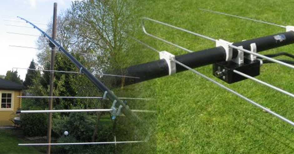 A ten element ultra-lightweight yagi beam antenna for 144 MHz based on YU7EF design concept
 -
 The HyGain LJ-153BA a monoband 3 element Yagi, designed for the 15 m band 21.00 - 21.45 MHz
 -
 **LDG Z100** automatic tuner repair focuses on toroid replacement and troubleshooting. The guide provides detailed steps for diagnosing and fixing common issues with the toroid, which is crucial for the tuner's performance. It includes specific instructions on disassembling the unit, identifying faulty components, and sourcing replacements. The document is technical, requiring familiarity with electronic components and soldering techniques. It emphasizes the importance of using the correct toroid specifications to ensure optimal functionality. Successful repair of the **LDG Z100** ATU restores its ability to match a wide range of antennas, enhancing transmission efficiency. The guide compares the performance before and after the repair, highlighting improvements in SWR readings and overall reliability. Practical application of this repair extends the life of the tuner, making it a cost-effective solution for amateur radio operators. The document serves as a reference for similar repairs on other models, providing insights into common issues and solutions. It is a valuable resource for those looking to maintain their equipment without resorting to professional services.
 -
 50MHz Collapsible 2 Element Mini Beam antenna, an overview the development of the 6MBA.
 -
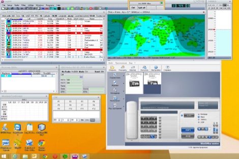 Operating a modern amateur radio station often involves integrating various software tools, and LogHX aims to provide a unified environment for Windows users. The software facilitates comprehensive QSO accounting, allowing operators to track contacts and manage both e-QSL and traditional paper QSL exchanges, including via QSL managers or direct methods. It also offers real-time QSO preview and integrates with popular callbook data for quick lookups. LogHX supports various logbook database searches and maintains statistics for numerous awards, a critical feature for serious DXers and contesters. The program handles logbook import and export in widely used formats such as _ADIF_ and _Cabrillo_, ensuring compatibility with other logging applications. Furthermore, it interoperates with Telnet clusters and third-party ham radio software, enhancing its utility in a networked shack environment. Key functionalities include antenna rotator control, editable macros for PSK, RTTY, CW, and SSB operations, and CAT control via _OmniRig_ or direct interfaces. Embedded modules like MMVari, MMTTY, and CWServer streamline digital mode operations, while its multi-window structure allows users to customize their screen layout, preserving valuable monitor space.
 -
 A 4 elements Yagi-Uda antenna for 144.3 MHz plan with dimensions and yagimax dimension calculation
 -
 For radio amateurs and electronics enthusiasts requiring specialized wiring solutions, Multi/Cable Corporation provides custom multi-conductor cable manufacturing services. They focus on made-to-order constructions, offering a broad range of specialty cable products including composite, instrumentation, electronic, flexible cord, thermocouple, high-temperature, and Mil-Spec wire and cable. Their capabilities extend to extensive customization of all cable components, ensuring precise adaptation to specific application requirements, which can be critical for bespoke shack setups or antenna control lines. With over 50 years in business, Multi/Cable emphasizes low minimum orders, quick turnarounds, and competitive pricing, making custom cable solutions accessible even for smaller projects. A case study highlights their role in helping an emergency vehicle lighting company expand offerings by providing versatile and cost-effective wire bundles, demonstrating their ability to support diverse technical needs beyond typical off-the-shelf options. They also provide reference data and guides on choosing conductors, insulation, and jacketing materials.