Search results
Query: Micro Vert
Links: 50 | Categories: 5
-
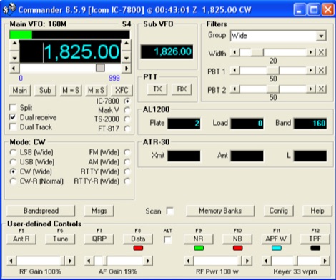 A free application that controls up to 4 Alinco, Elecraft, FlexRadio, Icom, JST, Kachina, Kenwood, TenTec, or Yaesu transceivers, switching between them manually or automatically based on frequency, and displaying frequency-dependent settings for devices like tuners and amplifiers; includes a bandspread, and supports transverters, frequency and mode tracking by an independent transceiver or receiver, SDR-based panadaptors, and SO2R switching with microHam or OTRSP-compliant devices.
 -
 The HB9ABX RoomCap antenna document details the construction and performance characteristics of a compact HF antenna design. It presents a series of comparative field tests conducted between July and September 2005, evaluating the HB9ABX antenna against established designs like the Microvert MV-500, Cushcraft R5/R7000 verticals, and a 5-element DJ2UT Yagi beam. Specific test scenarios include mobile installations, rooftop deployments, and comparisons on 20m, 40m, 80m, and 160m bands, with signal reports from various European and DX stations. The resource emphasizes the antenna's small physical footprint and its claimed efficiency across multiple HF bands. Test results consistently show the HB9ABX antenna performing comparably to, and often outperforming, larger reference antennas in terms of received signal strength, with reported differences of 1 to 2 S-points (6-12 dB) in many contacts. Notably, a 20m DX test on July 26, 2005, indicated the 1.3m HB9ABX radiator yielded 2-3 S-points stronger signals than an R7000 vertical for US DX stations. An August 12, 2005, test on 40m highlighted the HB9ABX's superior signal-to-noise ratio in urban QRM, demonstrating 10-18 dB better performance than an R7000. The document includes specific callsigns, signal reports, and QTHs for each comparison, providing empirical data for the antenna's performance claims.
 -
 11 Meter CB, 10 Meter Amateur Ham, FRS, GMRS Radios, Test Meters, Scanners, Antennas, Microphones, Power Supplies, Inverters, Accessories and Technical Reference Information.
 -
 Download this Microsoft Excel-based converter to import ADIF to Excel table and export the Excel Table to ADIF file format.
 -
 manufactures and distributes HF, VHF, UHF and SHF equipment covering 10MHz. - 47.0GHz. Our products include: Wireless LAN / WAN Bidirectional Linear Amplifiers, Low Noise Preamplifiers - LNA's, RF Linear Amplifiers, Relays, Transverter Systems, Frequency Translation Systems, Downconverters, Antennas, Parabolic Dishes, Coaxial Cable, Relays, Antenna Switches, Microwave Test equipment, PC controlled Receivers, Microwave Linear Amplifiers including models for Telemetry, Wireless, and CDMA applications.
 -
 Captures any audio from the Internet, records audio from CD, microphone, line-in, converts any sound formats to WAVE and MP3. Total Recorder records streaming audio, Mic input, Line-in input as well as CDs and DVDs, allows users to schedule any number of future recordings
 -
 The KD1JV "Melt Solder" Digital QRP SWR/Power Meter operates across the 160m to 6m bands, featuring 9.9-watt and 990-milliwatt power scales, a peak hold mode for SSB, and a VSWR scale from 1:1 to 9.9:1. It utilizes a _Stockton directional coupler_ wound on a single binocular core and an _Atmel AVR ATtiny26L_ microcontroller for processing. The design incorporates _W7EL diode compensation_ in a non-inverting amplifier feedback loop to address diode voltage drop and non-linear behavior at low power levels, with software corrections applied for improved accuracy, particularly at QRP power levels up to 5 watts. Construction details include parts placement, transformer winding instructions for #26 magnet wire, and calibration procedures using a 1.5V alkaline battery or an oscilloscope with a 50-ohm dummy load. Packaging options are discussed for fitting the board into an Altoids tin or a deeper Whitman’s Sampler tin, with considerations for battery life extension by adding a third or fourth battery. Accuracy tests performed at 7 MHz compare readings against a True RMS power meter based on an _Analog Devices AD8361_ chip, showing typical deviations of 0-5% across various power levels.
 -
 Presents a practical approach to constructing a portable, lightweight antenna support structure, ideal for field operations or temporary installations. The design utilizes readily available PVC pipe sections, allowing for a total height of **20 feet** and a transportable weight of **25 lbs**. Detailed material lists specify various PVC pipe diameters and lengths, along with couplers, tees, and elbows, facilitating a modular assembly that can be easily disassembled for transport. Accompanying the tower design, the resource also outlines the construction of a _MicroVert_ antenna, including formulas for radiator length, capacitance, and inductance. It provides guidance on creating a current balun using ferrite beads or a coax coil, and calculating counterpoise length for optimal performance. The antenna section includes a schematic diagram illustrating the connection of the SO-239 connector and counterpoise.
 -
 Over 45 years of amateur radio experience inform the homebrew projects detailed on this personal website, with a particular focus on microwave frequencies. The site showcases a 24 GHz transverter and a more recent 47 GHz transverter, demonstrating practical construction techniques for extreme high-frequency operation. These projects often involve custom circuit design and careful component selection to achieve stable performance at millimeter-wave bands. Key projects include a _harmonic converter_ for frequency measurement and a tracking spectrum analyzer, essential tools for microwave experimenters. The site also documents a CW sidetone generator and a TX/RX sequencer, illustrating fundamental building blocks for radio equipment. Details on a digital frequency meter and an S-meter/dBm meter provide insights into test equipment construction. Specific achievements, such as a **24 GHz** tropo QSO with DK3SE in 2021, highlight the operational success of these homebrewed systems. The content reflects a long-standing dedication to self-sufficiency in amateur radio, providing practical examples for those interested in building their own gear.
 -
 End-Fed Half-Wave Antennas (EFHWAs) are analyzed for their utility in portable QRP operations, emphasizing their simplicity, efficiency, and predictable radiation patterns compared to other portable antenna types. The discussion contrasts EFHWAs with vertical antennas, random length wires, and center-fed dipoles, highlighting the common pitfalls of each, such as ground system dependency for verticals and feedline issues for dipoles. The article details the electrical half-wavelength calculation using the formula L (Ft) = 468/F(MHz) and explains how EFHWAs can be resonant on harmonic frequencies, enabling multiband operation. Various deployment configurations are presented, including the inverted L, inverted Vee, sloping wire, and vertical setups, each with specific advantages for radiation angle and polarization. For instance, a vertical EFHWA offers a low angle of radiation suitable for DX contacts without requiring an extensive ground system. The resource also addresses the counterpoise requirements, suggesting a quarter-wavelength wire or connection to a metallic structure for decoupling. A schematic diagram for a simple parallel-tuned circuit tuner, based on the _Rainbow Bridge/Tuner_ design, is provided, detailing component values for 30 and 40 meters, including a 6 microhenry toroidal inductor and a 20-100 picofarad mica compression capacitor. The tuner's adjustment process for SWR matching is also outlined.
 -
 Presents the design and construction of an automatically tuned 7-30 MHz mobile HF vertical antenna, originally published in _QEX / Communication Quarterly_ in 2003. The resource details a base-loaded vertical antenna system that mounts on a vehicle's roof, incorporating a variable inductor as its loading coil. A three-legged chariot, driven by a modified model airplane servo, travels inside the coil to adjust inductance. The control unit, featuring a _Basic Stamp microcontroller_ and SWR sensor, emulates a Kenwood AT-50 tuner for seamless integration with a _Kenwood TS-50_ transceiver, allowing automatic tuning across all ham bands from 40 to 10 meters. The project emphasizes practical application, providing a solution to the narrow-banded nature of mobile HF antennas and the inconvenience of manual band changes. It achieves a maximum SWR of 1.3:1 across its operating range. The mechanical design is thoroughly documented with detailed drawings, including a full-resolution GIF and AutoCAD R14 DWG files, illustrating components like the stainless steel whip, PVC coil tube, and the servo-driven chariot mechanism. Construction requires a lathe, but the author notes it can be accomplished with a hobby lathe, making it accessible to those with moderate mechanical skills.
 -
 PA3FWM's software defined radio (SDR) page documents his extensive hardware and software development efforts between 2004 and 2009. Initial experiments utilized a direct conversion receiver with 90-degree phase difference, feeding a PC soundcard at 48 kHz sample rate, covering 24 kHz of spectrum around a 7080.5 kHz local oscillator. This setup, similar to AC50G's QEX 2002 article, allowed for basic I/Q signal processing to distinguish signals above and below the LO frequency. Limitations included fixed crystal frequencies, 16-bit dynamic range, and narrow bandwidth. Subsequent hardware iterations aimed for enhanced performance, incorporating external 24-bit ADCs with 192 kHz sample rates, connected via 10 Mbit/s Ethernet. A **MC145170-based PLL** and programmable octave divider provided a 58 kHz to 30 MHz tuning range. The **Tayloe mixer** was employed, with differential outputs feeding a PCM1804 ADC. An ATmega32 microcontroller handled serial data conversion to Ethernet frames, though without CRC calculation due to processing constraints. Later designs integrated AD7760 2.5 Msamples/second ADCs and a Xilinx Spartan-3 FPGA, enabling direct reception of 0-1 MHz spectrum and eventually 2.5 MHz bandwidth across the shortwave spectrum. Software was refactored to use an initial 8192 non-windowed FFT for efficient high-bandwidth processing. The project culminated in a two-way QSO on 21 MHz using the developed hardware and software, demonstrating transmit capabilities with a D/A converter. The system exhibited a 2.5 MHz wide spectrum display and a zoomed 19 kHz display, capturing signals like ionospheric chirp sounders and RTTY contest activity. Challenges included noise leakage from digital circuitry and cooling for high-power dissipation components.
 -
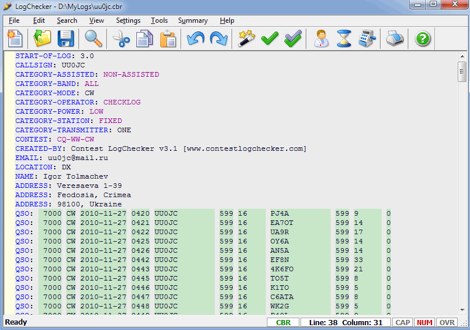 Contest LogChecker is a set of contest tools for Microsoft Windows, combining advanced text editing with keyword highlighted, and the ease and flexibility of import, export, statistics and charting utilities. With LogChecker you can edit, fill in the log, check Cabrillo Format and Header, convert files from the most popular logging software to Cabrillo, print customizable files, calculate statistics and export logs to RTF, PDF or HTML for publishing. You can examine a log in many different ways by highly interactive methods. LogChecker includes a Master Callsign Database tool for managing databases, which have been generated from actual contest logs. Commercial
 -
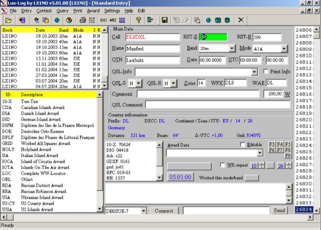 For amateur radio operators running Microsoft Windows XP or later, Lux-Log provides a robust logging and contest software solution, designed by Norbert Oberweis, LX1NO. It is capable of managing over 30,000 logbooks within a single database and image copy, offering comprehensive data handling features. The software facilitates data import and export via **ASCII** and **ADIF** formats, ensuring compatibility with other logging applications, and includes an integrated tool for converting data from other programs into ADIF. It provides instant feedback on previous contacts and country information during data entry, alongside static or serial value generation for contesters. Lux-Log integrates a versatile award module, currently supporting 123 definitions for popular awards such as DXCC, WAZ, WAS, US Counties, IOTA, and more. Operators can generate pre-defined and user-definable data queries, visualize statistics through bar/pie charts, and print QSL labels. The software also interfaces with the RAC Callbook and HamQTH, supports LoTW, and offers radio control for Icom and Yaesu FT-857 transceivers. Additionally, it supports telnet connections to internet clusters and integrates with K1EL's WinKey for CW generation, making it a comprehensive tool for both general logging and contesting activities.
 -
 A micro processor interface that converts PC keyboard code into Morse code
 -
 Terrasat Communications specializes in advanced RF technology for satellite communication, focusing on _Intelligent Block Up Converters_ (IBUCs) and Solid State Power Amplifiers (SSPAs). These products are engineered to enhance satellite link performance, offering features like extended frequency ranges and high power efficiency. The IBUC series, for instance, integrates a BUC with an SSPA, enabling operators to install, configure, and monitor units for both commercial and military satellite applications, ensuring reliable, high-performance connectivity worldwide. The company's offerings support various satellite bands, including C, X, Ku, and Ka, providing solutions for diverse operational requirements. Their technology is designed for robust field performance, with products like the _IBUC2_ and _IBUCG_ models demonstrating the integration of advanced diagnostics and control capabilities, which are crucial for maintaining optimal signal integrity in demanding environments. Terrasat's focus on _SSPA_ technology underscores a commitment to power efficiency and compact design.
 -
 Progress in Design of Extremely Short Transmitting Antennas Short and still efficient, how is that possible? By Juergen Schaefer, DL7PE author of the MicroVert antenna concept. The MicroVert introduced in this document is an extremely short and hardly visible short-wave antenna with outstanding radiation properties
 -
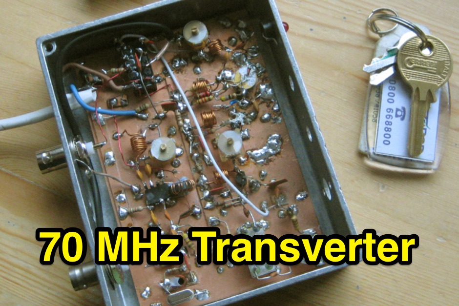
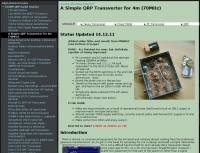 Transverter for 70MHz, a project by G3XBM
 -
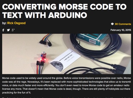 A sketch to read the input from the microphone and translate the dots and dashes into ASCII characters.
 -
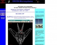 NEC4WIN is a 32 bits commercial antenna simulation software based on MININEC3 developed by the Naval Ocean Systems Center in the 70s and 80s. It runs under Windows and can be used to simulate, analyze and optimize wire antennas, beams, verticals, etc. NEC4WIN has limitations. They are the same as Mininec3 on which the engine is based.
 -
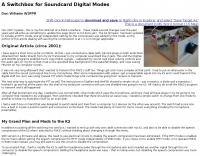 The Elecraft K2 transceiver requires specific modifications for optimal soundcard digital mode operation, particularly for PSK31. The original article, circa 2001, details initial challenges with manual PTT and speech compression settings. A key modification involves adding headphone audio and a compression disable signal to the K2's microphone jack, utilizing pins 4 and 5. The **COMP0** signal, active low, is shorted to ground via a non-inverting open collector switch circuit, comprising two resistors and two transistors, mounted on the SSB board near U3. This circuit provides effective control of an analog signal line with good noise immunity. The switchbox itself repurposes a computer COM port switch, using only two of its original connectors and four of the nine poles. It integrates a microphone preamplifier, a PTT circuit built with 'flying leads' construction, and RCA jacks for soundcard connections. A trimpot adjusts the audio drive to the K2. The central DB9 connector links to the K2's mic connector via a shielded RS232 serial cable, ensuring proper grounding and signal routing. An external footswitch PTT jack is also included. Further enhancements include a **noise-canceling microphone** preamp based on a QST December 2000 article, adapted for Heil mic elements. This preamp, built with pseudo-Manhattan style construction, provides a gain of approximately 2 by changing emitter resistors (R9 and R16) from 680 ohms to 330 ohms. A 10-ohm series resistor and 47 µF capacitor on the +5V supply mitigate noise spikes.
 -
 This is a prototype of the WA4DSY 56KB RF modem. It is intended for use on amateur packet radio networks. The modem generates RF in the 28 to 30 mhz range and requires and linear transverter to convert the signal to a UHF or microwave ham band
 -
 70 MHz transverter, 4m band, by G3XBM
 -
 A 200 kHz bandwidth digital transmission system for image transfer in the Amateur Service is under development, specifically targeting VHF allocations. John B. Stephensen, KD6OZH, leads this project under an FCC Special Temporary Authority (STA) valid until September 10, 2006, authorizing emissions up to 200 kHz bandwidth in the 50.3-50.8 MHz segment. Current regulations typically limit bandwidths to 20 kHz on VHF amateur bands, making this STA crucial for testing wideband digital modes. The modem, a modified **OFDM** (Orthogonal Frequency Division Multiplexed) unit, was initially tested on the 70-cm band. It splits a high-rate data stream into multiple low-rate subcarriers to mitigate multipath echoes. The system uses a DCP-1 card with a Xilinx XC3S400 FPGA and Oki Semiconductor ML67Q5003 microcontroller. The transmitter, located at 36d 46m 30s N, 119d 46m 22s W, generates 150 WPEP into an 8 dBi gain vertical antenna, while the mobile receiver uses a Ham-stick. Three data formats for 50, 100, and 200 kHz channels are being tested, with encoded data rates of 96, 192, and 384 kbps. Verilog code for the VHF OFDM modem is 95% simulated, with modifications from the UHF version including increased filter coefficient precision and a change from Ungerboeck **TCM** to BICM for improved performance over fading paths. Final tests will involve one-way over-the-air measurements of bit error rates and coverage area.
 -
 Design and manufacture application specific microwave and RF amplifiers, upconverters, downconverters and multifunction assemblies.
 -
 Top quality Microwave Phase Locked oscillators for DB6NT, DEMI and homebrew microwave transverters, and other support products.
 -
 This program converts an ADIF report file from ARRL's Logbook of the World (LoTW) to comma-separated value (CSV) format so that it can be read into a spreadsheet program like Microsoft Excel.
 -
 This online project guide details the construction of a homebrew boom microphone system. It details the assembly of a microphone shell from a 3/4" PVC pipe section and an end cap, requiring a drilled hole for a snug fit of the electret or condenser mic element. The internal wiring schematic specifies a **2.2 K** resistor and a **47 uF** polar capacitor for signal conditioning, with a circuit diagram provided for integration with IC-706 series transceivers. The guide outlines the use of CAT-5 cable for internal connections, incorporating strain relief at the rear of the mic shell, and an inline 3.5 mm jack to facilitate an external _PTT_ line, designed for a foot-mounted switch. Further construction involves fabricating a microphone shock mount from a 2-inch PVC connector, detailing the creation of four "fingers" and the insertion of screw-eyes for attaching elastic bands, which are twisted 180 degrees for tensioning and vibration isolation. A foam wind screen is also incorporated into the microphone assembly, secured with adhesive. The boom arm itself is repurposed from an articulated architect lamp, with the original lamp assembly converted into a **60 watt** resistive load for testing power sources. Microphone cabling is secured to the boom arm using wire ties, ensuring sufficient slack at hinge points to maintain articulation. The boom base is mounted to a bookshelf, requiring specific positioning to achieve proper microphone placement in front of the operator. Performance evaluation of the microphone system is conducted through on-air audio signal reports from other amateur radio operators. DXZone Focus: Online Project Guide | Boom Microphone Construction | Electret Mic Element | PTT Line
 -
-
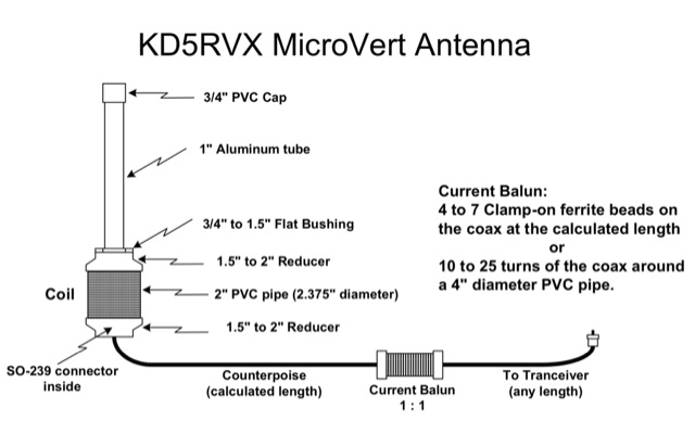 A Microvert antenna by KD5RVX based on the original microvert concept by DL7PE. PDF includes a 20 foot portable PVC tower project
 -
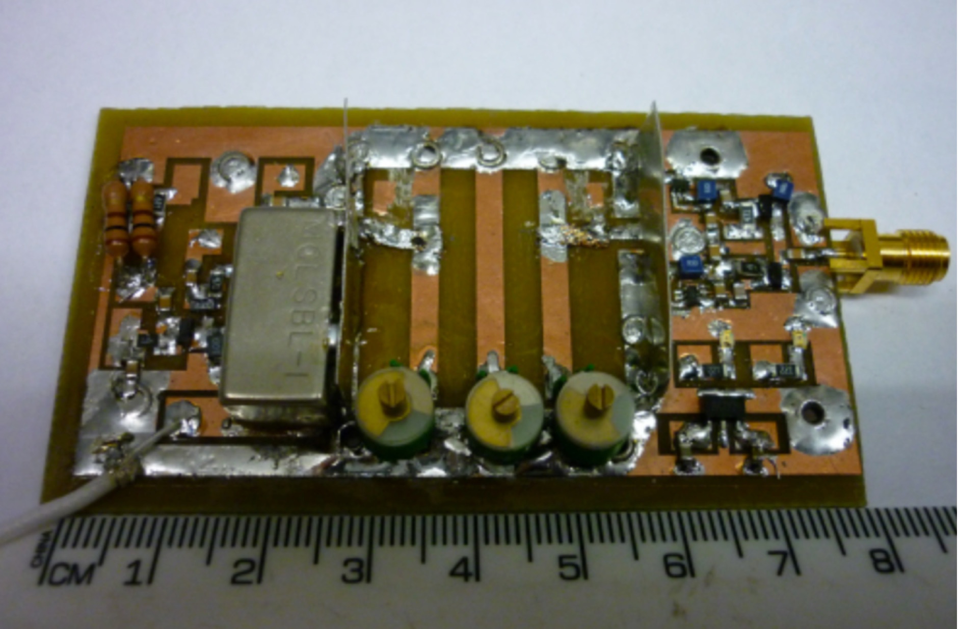 A low cost, low power microwave transverter so that you can operate easily on 70cm band even with a HF or VHF transceiver
 -
 Simulation of a top loaded vertical antenna for 1.2 MHz
 -
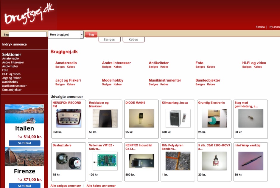 Brugtgrej presents a Danish online classifieds platform specifically for amateur radio operators and electronics enthusiasts. The platform facilitates the buying and selling of used equipment, including transceivers like the Icom IC-7410, various components such as X'TAL FILTER FMT-15A and TRANSISTOR 2SC3019, and accessories like Sadelta microphone capsules and SMA to SMA extenders. Users can post free advertisements for items they wish to sell or acquire, covering categories beyond amateur radio, including antique radios, military radios, and radio tubes. The site lists active advertisements, with 3136 online ads and 167 online users at the time of analysis, indicating a dynamic marketplace. It also features a forum for community interaction, discussing topics like repeater rings on 1297 MHz and FT8 activity. The platform's structure supports both 'Sælges' (for sale) and 'Købes' (wanted) listings across its various sections. Specific items observed include a Miniwatt pentode 4689, various capacitors and coils, and general electronic components, demonstrating the breadth of offerings available to the amateur radio community.
 -
 GoGreenSolar provides comprehensive solutions for **DIY solar panel systems**, catering to both homeowners and professionals seeking energy independence or reduced utility costs. Their offerings include a variety of solar kits such as Grid-Tie, Off-Grid, and Battery Backup configurations, designed to integrate seamlessly with existing utility infrastructure or provide complete autonomy in remote locations. Customers can select from Microinverter or String Inverter kits, along with essential components like **solar panels**, inverters, batteries, and racking systems, all curated from reputable brands known for efficiency and durability. The company emphasizes end-to-end support, from initial consultation and custom system design to providing easy-to-follow installation manuals. They offer financing options, including quick-approval loans with zero down payment, and a money-back guarantee if a solar permit is not approved. The platform also features a solar calculator and a questionnaire to help users determine the most suitable system for their specific energy requirements and property characteristics. GoGreenSolar aims to simplify the solar adoption process, enabling significant savings on energy bills and labor costs. Their approach focuses on empowering users to install their own systems with expert guidance, ensuring optimal performance and a secure energy future for homes and businesses.
 -
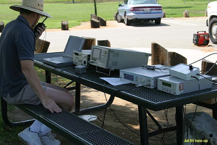 The San Bernardino Microwave Society, operating under the callsign _W6IFE_, serves as a significant technical hub for amateur radio operators specializing in frequencies above 1 GHz. This organization's influence extends across Southern California, providing a centralized resource for advanced RF experimentation and **regional frequency management** within the microwave spectrum. Its permanent value lies in its extensive archive of technical papers and project documentation, which are critical for operators engaged in high-frequency design and deployment. The society's infrastructure is primarily intellectual, focusing on the dissemination of specialized knowledge rather than a conventional repeater network. It offers a robust collection of technical papers from prominent members like K6PIP, K6BLG, and WA6EXV, covering topics such as Rubidium oscillator data, logging software, and filter design. This resource facilitates advanced amateur radio operations, including participation in microwave contests and the development of custom transverters for bands like 24 GHz. The site also details various member projects, such as the Owens Valley Radio Observatory Project, showcasing practical applications of **RF propagation analysis** and system integration. DXZone Focus: Microwave | Technical Papers | RF Propagation | Contest Results
 -
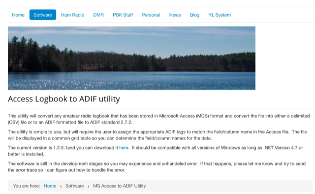 This utility will convert any amateur radio logbook that has been stored in Microsoft Access MDB format and convert the file into either a delimited CSV file or to an ADIF formatted file
 -
 The ZS1J/B beacon operates on 28.2025 MHz with 5 Watts output to a half-wave, end-fed vertical antenna, initially installed in 1977 as ZS5VHF near Durban. The 10-meter transmitter is a modified 23-channel CB radio, and the identification keyer uses a diode matrix unit with TTL ICs from the same era. After relocation to Plettenberg Bay in 1993, the beacon has been in continuous service, with additional QRP transmitters later installed for other bands. In 1994, a single-transistor, 80-meter, 0.5-watt QRP transmitter with a half-wave dipole was added on 3586 kHz, followed by a 160-meter, 0.5-watt unit on 1817 kHz. A 30-meter, 0.5-watt transmitter was installed in 1996, operating on 10.124 MHz. In 2002, a 40-meter QRRP beacon on 7029 kHz, with an output of 100 microwatts, achieved DX reports up to 1100 km from ZS6UT in Pretoria. Best DX reports for the 80m and 160m beacons came from 9J2BO.
 -
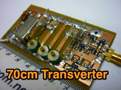 The project in this article illustrates how to do this in a simple and low cost way so that you can easily access the microwave bands using the existing HF or HF/VHF transceiver as IF.
 -
 DL7JV shares his practical experience building and testing capacitive antennas, initially skeptical of their performance compared to magnetic loops and mono-band dipoles. His interest was piqued after hearing a Spanish station running 100 Watts on 80 meters with a 1-meter Micro Vert, making DX contacts into PY and UA0, despite the antenna being only 4 meters high in a garden. This prompted DL7JV to investigate further, consulting resources from DL7PE and DL7AHW, the latter providing DOS programs like "Mitspule.exe" and "Spulenprg.zip" for calculating antenna dimensions and coil conversions. The article outlines the construction of two prototype antennas: one for 7.050 MHz using a 75mm PVC pipe and another for 3.550 MHz with a 110mm PVC pipe. Both designs feature aluminum foil condensers and coils wound from 1mm² H07V-K wire. DL7JV provides specific measurements for the condenser capacitance, surface area, diameter, height, coil inductance, turns, and wire length for both 40m and 80m versions, along with RG58 feedline lengths. Initial reception tests for the 7 MHz antenna, placed indoors, yielded impressive S9+5 signals from a German station compared to an S8 from a 42-meter roof-mounted loop, even hearing a Japanese station. Transmission attempts on April 4, 2004, despite moderate solar storm conditions, resulted in successful QSOs on 7 MHz with EA5OT (579/559) and on 3.5 MHz with YT1NT (579/559) and G4KKI (579/559) using 100 Watts. DL7JV notes the antenna's sensitivity to coordination and feedline layout, suggesting a modification from DL7AXO involving a 500pF fixed capacitor and coil tap for improved SWR stability. He concludes that while the capacitive antenna is space-saving and performs well for reception and 100W transmission indoors, its transmit performance doesn't yet match larger antennas, with further outdoor field tests planned. DL7JV also intends to build a 1.8 MHz version.
 -
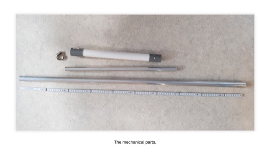 A mircovert antenna assembled for the 40m version of the DL7PE antenna. A one meter long aluminum tube with 24mm diameter is used for the base (element 1) and a 50cm aluminum tube with 20mm diameter for element 2 (the extention). A pvc pipe, 34cm long and with a diameter of 38mm, is used to wind the coil on (1mm enamelled copper wire).
 -
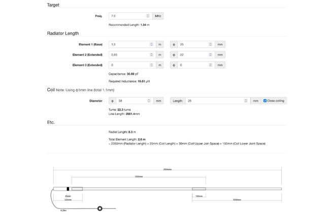 Online antenna calculator for the microvert capacitive antenna
 -
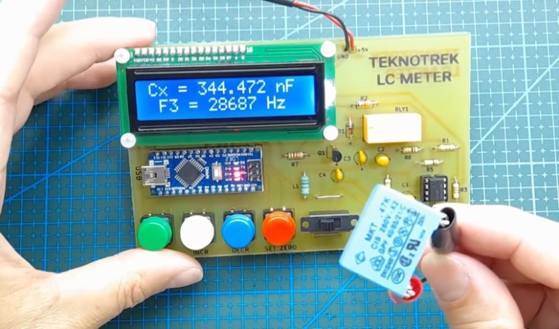 An **Arduino LC Meter** provides an accessible solution for precisely measuring inductance and capacitance values, crucial for RF circuit design, filter tuning, and troubleshooting in amateur radio applications. This project details the construction of a low-cost, accurate instrument using readily available components, making it an attractive alternative to commercial units for hams and electronics enthusiasts. The build process involves assembling a resonant circuit, integrating an Arduino microcontroller for frequency measurement, and displaying results on an LCD. Key components include an Arduino Uno, a 16x2 LCD, a 74HC14 Schmitt trigger inverter, and a few passive components. The design leverages the Arduino's processing power to calculate L and C values from resonant frequency shifts. Calibration procedures are outlined to ensure measurement accuracy, which is vital for critical RF work. The project includes schematics, a parts list, and the necessary Arduino code, enabling hams to construct a functional LC meter for their workbench.
 -
 A data converter for the Tandy WM918 weather station. The Weather APRS data converter project aims to create an interface to interpret data from the popular Tandy WM918 weather station and format it for transmission over packet radio. The South East Radio Group in South Australia has established a network of these weather stations to provide amateurs with regularly updated weather data. However, the WM918's data output is not structured for APRS weather reporting. This project describes a solution using a PIC microcontroller to convert the WM918 data into APRS-compatible strings that can be sent as beacons or connected packets. The interface offers features like position/positionless data, connected/beacon modes, and metric/imperial units. The goal is to create an interconnected weather reporting system for amateur radio operators
 -
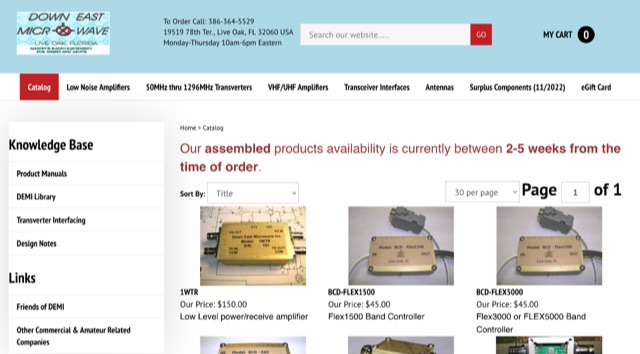 Manufacturer of 50MHz, 70MHz, 144MHz, 222MHz, 432MHz, 900MHz or 1.2GHz transverters and VHF UHF amplifiers
 -
 Nuts & Volts, founded in 1980, began as an advertising-based newsprint and evolved into a leading electronics magazine. A major shift came in 1992, introducing content-rich articles, columns, and DIY projects, cementing its role for hobbyists and professionals. Reformatted in 2003 to standard magazine size, it now averages 100 full-color pages on high-quality paper. Celebrating 40 years, Nuts & Volts remains the longest-running U.S. electronics publication, with loyal readers and advertisers since the 1980s. Its diverse topics span robotics, circuit design, automation, microcontrollers, and more, appealing to all skill levels.
 -
 Details the construction and performance of a phase-controlled receiving array, specifically a **MicroSWA** variant, optimized for QRP low band fox hunting on 40M and 80M. The resource documents the author's iterative design process, addressing significant regional noise challenges encountered during 0100-0230 UTC fox hunt periods. Initial experiments involved a director wire on a 40M vertical, yielding limited improvement, prompting a shift towards advanced null-steering techniques. The project leverages concepts from Victor Misek’s "The Beverage Antenna Handbook" and Dallas Lankford’s extensive work on phased receiving antennas for urban lots. A key modification involved integrating a new passive phase control box and a push-pull **Norton common base preamp** using 2N5109 transistors, designed for high third-order intercept performance to maintain weak signal integrity amidst strong adjacent signals. The system incorporates Faraday-shielded transformers with RG174 primaries on -75 ferrite cores, housed in ABS plastic pipe. Performance tests confirmed the MicroSWA's ability to produce deep, steerable nulls, achieving approximately 30 dB noise reduction on 160M, 80M, and 40M. This enabled detection of QRP signals undetectable on conventional transmit antennas. The final unit includes front panel controls, a 10-11 dB preamp, and a robust power conditioner, demonstrating effective noise mitigation for challenging low band QRP operations.
 -
 The page features a spreadsheet that calculates power in watt and dBm based on voltage and impedance, power in dBm with a given power and impedance, voltage in millivolts with a given power and impedance, and more. It also converts between millivolt, microvolt, volt, watt, and milliwatt. Useful for hams looking to accurately calculate power and voltage values for radio equipment. Last updated in December 2014.
 -
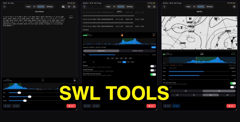 SWLTools, an iOS application for iPhone and iPad running iOS 17+, provides real-time decoding of various digital modes. It automatically locks onto CW tones, measures sending speed, and collects callsigns, distinguishing valid entries from misreads for a reliable log. For RTTY and SITOR-B, the app allows users to set shift and speed, then automatically tunes to the two tones for text reception, supporting marine bulletins, press agencies, and NAVTEX. The application also decodes WEFAX, building charts line by line for direct saving to the photo library, and processes ACARS aircraft messages, including CRC checks for data integrity and mapping of position reports. Beyond decoding, SWLTools integrates a GPU-accelerated FFT spectrum analyzer, a scrolling waterfall display with frequency cursors, and an adjustable FIR bandpass filter to isolate signals. It supports IQ signal analysis from receivers via two-channel audio interfaces, correcting mirror images. Flexible audio input options include the built-in microphone, USB audio dongles, and Bluetooth sources, with diagnostics for audio routing and buffer status. The app records audio, plays it back, and converts recordings into shareable videos, while decoded texts and charts are also savable and shareable, with all timestamps in UTC.
 -
 The W6PQL 23cm Beacon Project describes a **1296 MHz** beacon designed for microwave propagation studies and equipment testing, capable of 30 watts output. It utilizes a PIC 16F628A microcontroller to generate CW and FSK keying for a crystal oscillator, followed by a series of frequency doublers and triplers to reach the target frequency. The final power amplification stage employs a Mitsubishi M57762 module, providing a robust 10-watt RF output. The design emphasizes stability and reliability for continuous operation, with the microcontroller code, written in assembly, provided for customization of the beacon's callsign and message. Originally located in CM97am and aimed at 140 true, the beacon used four 4-foot Yagis stacked vertically for a total ERP of 3kW. The article includes schematics, parts lists, and construction notes to guide builders, along with antenna pattern measurements. Although the beacon itself is no longer in service as of August 2010, the detailed documentation remains a valuable reference for amateur radio operators interested in building similar **microwave** projects or understanding beacon operation.
 -
 The **Amateur Radio** community on Microsoft Teams provides a platform for hams to connect through chat and video calls. It features five distinct channels, facilitating structured discussions on various topics, akin to a community forum without advertisements. Users can schedule events for group video chats or engage in one-on-one calls, with user status indicators showing availability. The platform supports sharing messages, files, and both video and audio communications within a defined group. An open video chat room is also available, accessible even to non-community members, allowing broader participation. The resource details how to join the existing 'Amateur Radio' community group and provides links to a blog post and a YouTube video for new users to understand Teams Communities.