Search results
Query: all band dipole
Links: 114 | Categories: 2
Categories
-
 The G5RV antenna, with an overall length of **31.10m (102ft)**, functions as a 3/2-wave on 20 meters when installed horizontally at 12m (39ft), exhibiting a resonant frequency of 14.150MHz and an approximate resistance of 80 ohms. Its 10.36m (34ft) stub line, designed as a 1/2-wave on 14.150MHz with a 0.97 velocity coefficient, acts as an impedance transformer across other bands, aiming for multiband operation without traps. On 20m and higher frequencies, the G5RV demonstrates improved gain compared to a standard dipole, attributed to the _collinear effect_ from multiple 1/2-waves along the wire. The original design sought a multiband solution for limited spaces, often requiring an Antenna Tuning Unit (ATU) for effective operation across bands like 80, 40, 30, and 20m, particularly with modern solid-state PAs. Variants, such as the F8CI modification, incorporate a 1/4 current balun at the stub line's base for symmetrical-to-asymmetrical transition, known as a _remote balun_. Proper flat-top or inverted-V installation is critical for maintaining symmetry and collinear gain, with inverted-V apex angles below 120° progressively diminishing higher-band performance.
 -
 Details the construction of a J-vertical antenna specifically for the 10-meter band, offering a practical alternative to a _Slim Jim_ design for 28 MHz. The resource outlines the use of aluminum tubing for the half-wave vertical section and coaxial cable for the quarter-wave matching section, providing specific calculations for element lengths based on frequency and coaxial cable velocity factor. It contrasts the performance of the J-vertical with center-fed dipoles and end-fed verticals, noting superior results in previous comparisons. The article further presents a more recent iteration of the J-vertical, constructed using a fiberglass pole and insulated wire, with updated dimensions for 28.8 MHz. It includes practical advice on weatherproofing connections and securing the antenna for durability against adverse conditions, referencing the survival of an original _J Vertical_ during 110 MPH winds in 1987. The SWR performance is reported as 1.1:1 at 28.6 MHz, maintaining below 1.5:1 across 28.3 to 29 MHz.
 -
 The boomless quad antenna is a unique design that offers versatility for amateur radio operators. This antenna consists of two half-wave dipoles arranged in a square or circular shape, allowing for both vertical and horizontal polarization depending on the feed point. The design facilitates easy installation and rotation, making it suitable for various operating conditions. The construction utilizes strong materials, such as bamboo, and incorporates waterproofing techniques to enhance durability. This project outlines the necessary dimensions and materials, including copper wire and insulators, to successfully build the antenna. It emphasizes the importance of tuning each radiator element for optimal performance. The boomless quad is particularly effective across multiple HF bands, including 14 MHz, 21 MHz, and 28 MHz. By following the detailed instructions, operators can achieve a reliable and efficient antenna setup that enhances their DXing and contesting capabilities.
 -
 Determining the actual need for an antenna tuner often hinges on the specific antenna and feed line configuration in use. While many hams believe a tuner is always essential, its primary role is to present a 50-ohm impedance to the transceiver, not to "tune" the antenna itself. For instance, a resonant dipole fed with _coaxial cable_ at its design frequency typically requires no tuner, as the feed line impedance closely matches the radio's output. However, operating a non-resonant antenna, or using a resonant antenna on multiple bands, frequently necessitates a tuner to manage high Standing Wave Ratio (SWR) on the feed line. The article clarifies that a tuner placed at the transceiver only matches the radio to the feed line, not the antenna to the feed line. For maximum efficiency with a non-resonant antenna, an _automatic antenna tuner_ (ATU) or a remote tuner placed at the antenna feed point is often more effective, minimizing losses in the feed line. The discussion also touches on the practical implications of SWR, noting that modern transceivers often fold back power at high SWR, making a tuner a practical necessity to achieve full output power, even if the antenna itself is not perfectly matched.
 -
 Details the construction and optimization of antenna systems for amateur radio satellite operations, focusing on practical, homebrew solutions for VHF/UHF bands. It covers building _groundplane antennas_ from salvaged materials, recycling old beam antennas into new configurations like a 2-meter crossed yagi, and constructing a 10-meter horizontal delta loop. The resource also explains antenna matching techniques, including folded dipole driven elements and quarter-wave transformers, along with the importance of accurate SWR measurements and minimizing coax loss. Demonstrates how to achieve a **1:1 SWR** by carefully trimming elements and adjusting radial angles on groundplane antennas. It provides insights into selecting appropriate coax and connectors, highlighting the benefits of Belden 9913 for low loss and the proper installation of _N-connectors_. The article also addresses RFI mitigation from computer birdies and presents a design for a silent triac antenna control circuit, offering practical solutions for common satellite station challenges.
 -
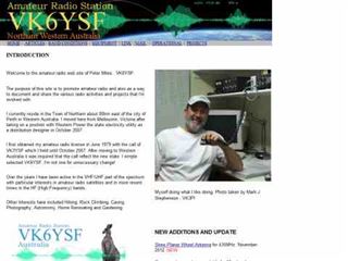
 Antenna suitable for all the HF amateur bands, including the so called WARC bands by vk6ysf
 -
 Presents a practical design for a **crossed-dipole turnstile antenna** specifically engineered for 2-meter Amateur Radio Direction Finding (ARDF) events. The author, WB6RDV, details a robust, omnidirectional, horizontally-polarized antenna, addressing the international ARDF rules requiring such characteristics at a height of two to three meters above ground. This contrasts with the vertical polarization often used in Southern California, highlighting the design's adherence to specific event requirements. The electrical design employs a classic crossed-dipole with a 75-ohm phasing section, resulting in a slight impedance mismatch and an SWR of approximately 1.3:1 with a 50-ohm feedline. Construction utilizes readily available and inexpensive PVC plumbing components and 1/8-inch bronze welding rod for elements. The guide provides step-by-step instructions for mechanical assembly, including drilling element holes at precise 90-degree spacing and preparing the RG-179 matching section. WB6RDV shares insights from his own build experience, discussing the use of plated brass versus aluminum spacers for element attachment and the effectiveness of crimping as an alternative to soldering. The document also covers final assembly, including the integration of ferrite beads as a choke balun and options for weatherproofing and alternative mounting configurations, emphasizing the adaptability of the design for other VHF bands through scaling.
 -
 The multi-band trapped dipole is resonant on approx 3.7, 7, 14, 24 7 28.5 Mhz. The overall top length needs to be approximately 32.9 Meters
 -
 Modified version of the Telerana antenna which was orginially featured in the July 1979 issue of QST. The array is suspended within a framework made of fiberglass poles emanating from a central hub with the ends tied together with light weight rope around the perimeter. 10-15-20-30-40 meter band coverage
 -
 The cobweb antenna it is basically a 5 band antenna comprising of 5 full half wave dipoles for each band - between 10 meters and 20 meters, the antenna is also resonant on 6M and can be modeled even for VHF frequencies.
 -
 Attic Fan dipole antenna that allow to operate QRP from 40 metres to 10 metres, specifically 40, 20, 17, 15 & 10 meter band
 -
 This multiband wire antenna it is an off centre fed dipole, with 10 feet of vertical radiator, needs no tuner on 40m, 20m and 10m and works fine on all bands above 40m with a tuner, and even below 40m on 60m, and 80m.
 -
 Demonstrates the construction and performance of an updated ZS6BKW multiband dipole, a variant of the _G5RV_ antenna, specifically designed for HF operation. The article details a real-world installation using 13.5m copper wire elements and 12.2m of 450 Ohm ladder line, configured as a sloping inverted-V with the apex at 10m and ends at 4m above ground. It covers the critical aspect of impedance matching, incorporating an 8-turn choke balun at the feedline transition to RG-58U coax to mitigate RF common mode current. Measurements confirm favorable SWR readings below **1.3:1** on 7.1 MHz, 14.11 MHz, 18.06 MHz, and 24.8 MHz, indicating effective resonance across 40m, 20m, 17m, and 12m bands. The installation also shows usable SWR dips on 3.55 MHz (5:1), 29.02 MHz (2:1), and 50.84 MHz (3:1), extending its utility to 80m, 10m, and 6m with an antenna tuning unit. Initial on-air results report clear reception of stations over **5000km** away, validating its DX potential.
 -
 The total length of this antenna is 41m, height is about 11m, and diameter of element is 2mm. JA7KPI modified this antenna originally used as Inverted-V type of 80m band Dipole. Works on 40 - 80 meters band with acceptable swr.
 -
 Indoor multiband dipole with EZNEC data files for simulation and analysis. Includes details on construction, tuning, SWR plots, and software usage. This page includes two different dipoles, a first version for 20-10 meters and an extended version covering 40-10 meters allowing a full coverage of most used ham radio HF Bands.
 -
 The ZS6BKW multiband HF antenna, a design by ZS6BKW (G0GSF), functions effectively on multiple HF bands without requiring an Antenna Tuning Unit (ATU) for 40, 20, 17, 12, 10, and 6 meters. This antenna, approximately **27.51 meters** (90 feet) long with a 12.2-meter (40-foot) open-wire feeder, is a direct descendant of the _G5RV_ but offers superior multi-band resonance. It can be deployed as a horizontal dipole or an inverted-vee, with the latter requiring only a single support and maintaining an apex angle of at least 90 degrees to prevent signal cancellation. Performance data, recorded with an MFJ Antenna Analyser, indicates SWR values of 1:1 on 7.00 MHz (40m) and 14.06 MHz (20m), with SWR below 1.3:1 on 17m, 10m, and 6m. While primarily designed for these bands, the antenna can be adapted for 80m, 30m, and 15m with an ATU, preferably at the balanced feeder's base. The use of 450-ohm twin-lead for the feeder is recommended over 300-ohm for improved strength and reduced losses, especially in adverse weather conditions. This design, originally published in _RadCom_ in 1993 and featured in Pat Hawker’s "Antenna Topics," provides a compact and efficient solution for HF operation, particularly for those with limited space or resources.
 -
 A rotary trapped-dipole for 17 and 20 meters, as described by IZ7ATH, presents a practical solution for multi-band HF operation. The author, Talino, recounts his experience building this antenna for IK7ZCQ, detailing the evolution from an initial concept involving a grounded-driven element and gamma-match to a direct-fed, non-grounded design. His pragmatic approach, adapting available materials, is evident throughout the construction narrative, particularly with the use of eight tapered aluminum pipes for the driven element. Construction specifics include precise measurements for the aluminum tubing, with diameters ranging from 30 mm down to 16 mm, and a critical note on reducing tip thickness for weight optimization. The _traps_, initially a concern, are fabricated using 8 turns of RG58 coax on a 27 mm support, tuned to resonate at 18.1 MHz using a dip-meter. Talino emphasizes sealing the traps with RF glue and PVC tape to prevent water ingress, a crucial step for longevity. Field test results, conducted on a 10-meter pole in a clear garden environment, showed an SWR of 1.2:1 on 17 meters and 1.5:1 at 14.200 MHz. While SWR varied slightly when installed at Mario's QTH due to nearby objects, the antenna's performance remained commendable. The final half-dipole length is 46 cm for the 18 MHz tips, and the total weight is under 6 kg, with potential for further reduction.
 -
 The W3DZZ trap dipole is a versatile and economical antenna option for amateur radio operators looking to work multiple bands without the need for extensive equipment. This antenna design utilizes traps to allow operation on various HF bands, making it suitable for both casual operators and serious DXers. Its construction is straightforward, making it accessible for beginners while still providing excellent performance for seasoned hams. Constructed with readily available materials, the W3DZZ trap dipole can be built to fit specific band requirements, allowing operators to optimize their setup for the frequencies they intend to use. The design is particularly favored for its ability to maintain a low profile while delivering effective radiation patterns. Whether you're contesting or chasing DX, this antenna can enhance your station's capabilities without breaking the bank.
 -
 These omnidirectional antennas offer Horizontal polarization, and about 2.1 dbd of gain. They are much quieter than a dipole or a vertical, have a broader bandwidth and will usually out perform a dipole antenna.
 -
 The BV6 50 MHz Yagis resource details the construction of two distinct Yagi antenna designs for the 6-meter band, specifically a 1-wavelength (1wl) model and a 2.1-wavelength (2.1wl) model. The 1wl Yagi, with a boom length of 5.850m, achieves a gain of **9.4 dBd**, while the 2.1wl Yagi, spanning 12.90m, boasts a gain of **11.9 dBd**. These designs adhere to a proven methodology for optimizing current slope and maintaining constant phase delay across parasitic elements, ensuring high gain per boom length and an _excellent pattern_. Both designs target a 50-ohm input impedance, facilitating straightforward feeding with a robust folded dipole. Final verification using NEC-II software confirmed the antennas' exceptional stacking capabilities, yielding stacking gains exceeding **5.8 dB** for a 2x2 array with minimal mutual detuning. The resource provides common mechanical data, including boom and element diameters, and specifies element lengths corrected for boom diameter. While the original _DUBUS Technik V_ publication contained incorrect element lengths, this resource provides the accurate dimensions for proper construction, emphasizing the use of readily available materials for cost-effective amateur radio deployment.
 -
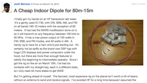 NC4JB Josh explain in this article how to setup a simple and cheap indoor dipole antenna that can be used on almost all HF bands
 -
 A shorten Dual-Band Dipole with overall length of about 11 m. For this antenna traps are substituted by inductors, in order to cover the 10 & 40 m. Bands.
 -
 End-Fed Half-Wave Antennas (EFHWAs) are analyzed for their utility in portable QRP operations, emphasizing their simplicity, efficiency, and predictable radiation patterns compared to other portable antenna types. The discussion contrasts EFHWAs with vertical antennas, random length wires, and center-fed dipoles, highlighting the common pitfalls of each, such as ground system dependency for verticals and feedline issues for dipoles. The article details the electrical half-wavelength calculation using the formula L (Ft) = 468/F(MHz) and explains how EFHWAs can be resonant on harmonic frequencies, enabling multiband operation. Various deployment configurations are presented, including the inverted L, inverted Vee, sloping wire, and vertical setups, each with specific advantages for radiation angle and polarization. For instance, a vertical EFHWA offers a low angle of radiation suitable for DX contacts without requiring an extensive ground system. The resource also addresses the counterpoise requirements, suggesting a quarter-wavelength wire or connection to a metallic structure for decoupling. A schematic diagram for a simple parallel-tuned circuit tuner, based on the _Rainbow Bridge/Tuner_ design, is provided, detailing component values for 30 and 40 meters, including a 6 microhenry toroidal inductor and a 20-100 picofarad mica compression capacitor. The tuner's adjustment process for SWR matching is also outlined.
 -
 This PDF document, authored by KT4QW in October 2004, details the construction and modeling of a dual-band, horizontally polarized hanging rectangular loop antenna for **10 and 17 meters**. The design, adapted from *The ARRL Handbook*, utilizes _NEC4WIN95_ software for scaling and optimization, targeting a 50 ohm feedpoint impedance. The resource includes a bill of materials, step-by-step construction instructions, and a discussion of the antenna's radiation characteristics. It presents NEC-generated elevation and azimuth patterns, comparing the loop's performance to a half-wave horizontal dipole at the same height and frequency. The 17-meter element is centered at 18.140 MHz for low SWR across the phone band, while the 10-meter element is centered at 28.500 MHz. Construction involves 14-gauge stranded copper wire and Schedule 40 PVC spreaders, with the total wire length calculated by the formula: Length in feet = 1005/MHz. The feedpoint impedance can be adjusted by modifying the rectangular aspect ratio. The document specifies hoisting the antenna to at least a half-wave above ground for testing. It notes that a balun was tested and found to have no measurable effect on SWR or radiation characteristics. A 2-meter scale model is presented to illustrate the physical design, and a "rotator" string is incorporated for directional adjustment up to 90 degrees.
 -
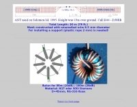 Mesh constructed with enamelled wire 0.5 mm diameter For installing a support (plastic rope 2 mm) is needed. Antenna used on Solomon Isl in 1995 H44/DJ9RB
 -
 The Buddipole website showcases a range of portable amateur radio antenna systems, including the **Buddipole**, Mini-Buddipole, Buddistick PRO, and BuddiHEX, designed for rapid deployment and multi-band operation from 40 meters to 2 meters. Each product page details specifications, operational modes (dipole or vertical), and compatible accessories like tripods, masts, and baluns. The site also features portable DC power management systems such as the PowerMini 2 and PowerPlus, which include integrated battery chargers and solar controllers, catering to off-grid or field day setups. Instructional videos demonstrate antenna assembly, tuning, and deployment techniques for various configurations, including the VersaTee vertical and Mini-Buddipole. Customer testimonials and DXpedition highlights, such as operations from Montserrat (VP2M) and Dominica (J38), provide real-world examples of the equipment's performance in challenging environments. The company, established in 2001, emphasizes modularity, versatility, and efficiency in its product line, all manufactured in the USA. Shipping information, a 30-day return policy with no restocking fee, and contact details for their Heber City, Utah facility are clearly presented. The site serves as a direct sales portal, offering a comprehensive catalog of antennas, power solutions, and components for portable amateur radio enthusiasts.
 -
 If you are looking for an easy antenna for your favorite band, you can't go wrong with an halfwavelenght dipole, all you need is 3 insulators and some wire
 -
 The page describes the construction of a simple omnidirectional, vertically-polarised dipole antenna for two metres using coaxial cable. It can be used indoors or outdoors, with no extravagant gain claims. The project is low-cost and can be completed in about 20 minutes.
 -
 This resource details the computer-optimized design of the _ZS6BKW_ multiband dipole, an evolution of the classic _G5RV_ antenna. It begins by referencing the original 1958 RSGB Bulletin article by Louis Varney G5RV, explaining the operational principles of the G5RV's flat-top and open-wire feedline on 20m and 40m, noting its impedance transformation characteristics for valve amplifiers of that era. The article then transitions to the rationale for optimizing the design for contemporary solid-state transceivers requiring a 50 Ohm match. The core of the project involves using computer modeling to determine optimal lengths for the flat-top and matching section, aiming for a VSWR of less than 2:1 on multiple HF bands. It discusses the process of calculating feedpoint impedance based on antenna length and frequency, referencing professional literature from Professor R.W.P. King at Harvard University. The analysis also considers the characteristic impedance (Z(O)) of the open-wire line, identifying a broad peak of adequate values between 275 and 400 Ohms. Specific design parameters for the improved ZS6BKW are presented, including a shorter flat-top and a longer matching section compared to the original G5RV, with a velocity factor of 0.85 for the 300 Ohm tape. The article confirms acceptable matches on 7, 14, 18, 24, and 28 MHz bands when erected horizontally at 13m, and also discusses performance in an inverted-V configuration, noting frequency shifts. The author, Brian Austin ZS6BKW, emphasizes the antenna's suitability for modern 50 Ohm coaxial cable without a balun.
 -
 JJ0DRC's HF multi-band delta loop antenna project, initially conceived during the waning peak of Cycle 23, addresses the common challenge of achieving effective DX operation from a small residential lot in Japan. Dissatisfied with a ground plane antenna's performance in SSB pile-ups, the author sought a beam-like solution without a tower, drawing inspiration from a JJ1VKL article in CQ Ham Radio Sep. 2000. The antenna, constructed in October 2000, employs two 7.2-meter fishing rods (37% carbon fiber, reinforced with cyano-acrylate glue and aluminum tape) and 1mm enameled wire, fed by an Icom AH-4 external antenna tuner. While the exact beam pattern remains unmeasured, JJ0DRC observed a significantly higher callback rate compared to dipole antennas, particularly on higher bands. The system's circumference length of 15-20m is crucial for maintaining a good beam pattern across HF bands, though performance on lower bands like 80m, 40m, and 30m becomes less directional as the length deviates from a full wavelength. Ongoing maintenance addressed degradation issues, including aluminum tape cracking and wire breakage at connection points due to strong winds (often exceeding 10-15m/s in winter). The author reinforced rod connections with IRECTOR PIPE SYSTEM components and INSU-ROCK ties, and improved wire attachment methods using Cremona rope and epoxy bond to enhance durability.
 -
 Put up the longest dipole you can fit, feed it with open wire line, connect it to the balanced output of your tuner and poof! Instant multiband antenna. Is life really that simple?
 -
 D3+ High Performance Antennas for Field Day. This article describes versatile broadband wire antennas. These antennas will double your effective radiated power over a dipole, will be easy and inexpensive to build and install, and will be simple to match.
 -
 The ZS6BKW wire antenna, a variant of the G5RV, utilizes a specific 13m (42.6 ft) length of 450-ohm window line as its matching section, feeding a 28.5m (93.5 ft) flat-top element. This design aims for lower SWR on 40m, 20m, 17m, 12m, and 10m compared to a standard G5RV, often achieving SWR values below 1.5:1 on these bands without an antenna tuner. The feedpoint impedance transformation provided by the window line allows for direct connection to 50-ohm coax on multiple bands. F4FHH's experience involved constructing the ZS6BKW and evaluating its performance against an _OCF dipole_ (Off-Center Fed) on various HF frequencies. The article includes observations on SWR readings and operational effectiveness, highlighting the ZS6BKW's suitability for multi-band operation. The antenna's overall length, including the flat-top and window line, is approximately **41.5 meters** (136 feet), making it a significant wire antenna for fixed station use. Comparative analysis with the OCF dipole provided practical insights into the ZS6BKW's advantages and limitations, particularly concerning bandwidth and tuner requirements.
 -
 The Classic Multiband Dipole Antenna QST article. The open-wire feed line dipole antenna is easy to install and offers surprising performance on several bands. You can install it in almost any configuration; it does not have to be strung in the traditional horizontal flat top
 -
 All Band HF Doublet for operation over all HF bands including 160m.
 -
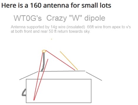 The WT0G crazy W dipole, a solution for 160 meter operations
 -
 The ZS6BKW antenna, a popular multiband wire antenna, offers improved band matching compared to the traditional G5RV. This construction guide details the process, beginning with specific dimensions: 13.11 meters (43 feet) for the 450-ohm ladder line and initial dipole arm lengths of approximately 14.8 meters each. It emphasizes the critical role of an _antenna analyzer_ for accurate tuning, particularly for determining the velocity factor of the ladder line and achieving a 1:1 impedance match. The article outlines the materials required, including a 1:1 current balun, 450-ohm window line, wire for the dipole arms, and a 50-ohm non-inductive resistor for testing. It provides a step-by-step procedure for cutting the ladder line to its electrical half-wavelength, explaining how to calculate the velocity factor using measured and free-space frequencies. For instance, a measured 50-ohm impedance at 12.54 MHz with a calculated free-space half-wavelength frequency of 11.44 MHz yields a velocity factor of 0.91. Final adjustments involve hoisting the antenna to its operational height and fine-tuning the dipole arm lengths to achieve optimal SWR, specifically targeting 14.200 MHz. The _ZS6BKW_ design is noted for its performance on 80m, 40m, 20m, 10m, and 6m, though it is not optimized for 15m operation. The author, _VK4MDX_, shares practical tips for durable construction using stainless steel wire and cable clamps.
 -
 Demonstrates the design and construction of a compact, portable multi-band mini-delta loop antenna, specifically optimized for /P (portable) operations from remote locations like Scottish islands. The resource covers the theoretical underpinnings of half-wave loops, contrasting closed and open configurations, and then details the application of a folded dipole principle to achieve a 50-ohm match for direct coax feed. It presents empirical formulas for calculating element lengths, considering the velocity factor of common wire types, and provides a detailed example for a 20m (14.175 MHz) version. The article includes a comprehensive table of dimensions and allowances for a five-band (20m, 17m, 15m, 12m, 10m) mini-delta beam, along with construction hints for the central support and balun. It specifies a 1:1 trifilar balun wound on a ferrite rod and describes the antenna adjustment process using an _MFJ-259B Antenna Analyser_. Initial test results indicate an SWR of 1:1 at resonance and a bandwidth of approximately 240 kHz on 20m, even at a low height of five feet above ground. The distinctive utility lies in its focus on a practical, easily deployable beam antenna for portable DXing, offering a viable alternative to more complex or larger arrays.
 -
 Demonstrates the design principles and performance characteristics of **corner reflector antennas**, emphasizing their high gain and directional properties. It covers critical design factors such as the corner angle and the spacing between the radiating dipole and the reflector vertex. The resource explains how reducing the corner angle increases gain but lowers feed impedance, making matching more challenging. Practical angles of 90 degrees or 60 degrees are discussed, with 90 degrees offering easier impedance matching despite slightly lower gain. Details key design considerations, including reflector side length exceeding two wavelengths and reflector width greater than one wavelength for a half-wave radiator. It specifies reflector construction using wire netting, sheet metal, or parallel metal spines spaced less than 0.1 wavelength. The article provides a table with general dimensions for UHF and VHF bands, noting typical impedance values of 50 to 75 ohms and expected SWR of 1.7:1 on the lower band edge. Adjustable radiator-to-vertex spacing is highlighted as crucial for final tuning.
 -
 Over 1,000 stations in approximately 60 countries were worked using this modified twin-lead folded dipole, demonstrating its effectiveness with just 4 watts on 20 meters. This design, adapted from an ARRL Handbook concept, eliminates the shorting strap found in traditional folded dipoles, simplifying construction while maintaining performance. It utilizes readily available 300-ohm TV antenna feeder ribbon, making it a cost-effective solution for radio amateurs. The antenna's robust construction allows it to handle up to 100 watts without issues, even without a **balun**. The inclusion of a variable trimmer capacitor at the stub provides flexibility for tuning across different frequencies within a band, a practical feature for operators using transceivers like the Icom 735. Formulas are provided to calculate the precise dimensions for any desired operating frequency, enabling customization for various **HF bands**.
 -
 Homebrew a cobwebb antenna for the HF bands. This page describe a cobwebb multiband antenna resonating on 14 18 21 24 and 28 MHz. The cobweb antenna model can be considered a fan dipole, or better, multiple dipoles fed in parallel.
 -
 The G5RV multiband HF antenna, designed by Louis Varney (G5RV) in 1946, is a popular compromise antenna offering good overall performance on most HF bands when paired with an external antenna tuner. The basic full-size G5RV measures 102 feet across the top for 80 through 10 meter operation and is fed at the center via a 34-foot low-loss feed-stub. This interaction between the radiating section and the feed-stub facilitates matching across 80-10 meters with a standard tuner, often eliminating the need for ladder line directly to the shack. The antenna's design center frequency is 14.150 MHz, configured as a 3/2-wave dipole on 20 meters, with its 102-foot length derived from long-wire antenna formulas. Construction details emphasize the matching section, which can be open wire, ladder line (window-type), or TV twin lead. Each type has a specific velocity factor (VF) affecting its physical length for an electrical half-wave on 14 MHz; for instance, open wire requires 33.7 feet (VF 0.97), ladder line 31.3 feet (VF 0.90), and TV twin lead 28.5 feet (VF 0.82). The article provides formulas for calculating these lengths and discusses the antenna's behavior on individual bands, from 3.5 MHz where it acts as a shortened dipole, to 28 MHz where it functions as two three-half-wave long-wire antennas fed in-phase. Practical construction notes include recommendations for vertical descent of the matching section, sealing the coax junction, providing strain relief, and winding a coaxial choke coil to mitigate common mode current. The resource also presents dimensions for double-size (204 ft) and half-size (51 ft) G5RV versions, along with their corresponding matching section lengths for various line types, making it a versatile reference for hams considering this classic wire antenna.
 -
 Centre fed half wave dipoles make great, simple and effective antennas for the HF bands. Sometimes however, the centre feed is not ideal. This great project will improve the overall antenna performance.
 -
 Extension to an existing fan dipole originally modeled for 40 20 and 6 meters. This modification will add 80 15 and 10 meter bands.
 -
 Interesting article on multiband fan dipoles. This article give an overview on designing this wire antenna, and planning a robust installation and proper feed line. Includes notes on setting up a commercial fan dipole antenna and on how diy your own.
 -
 Deploying robust antenna infrastructure for both fixed and portable operations often requires specialized support structures capable of withstanding environmental stresses while providing optimal radiating element placement. SMC offers a range of solutions, including pneumatic masts and push-up masts, designed to facilitate rapid deployment and reliable long-term support for various antenna types. Their product line encompasses antenna mounts, poles, and complete antenna systems, addressing the critical need for stable and efficient RF communication. The company's offerings extend to HF antennas, including dipoles and _NVIS_ (Near Vertical Incidence Skywave) antennas, which are crucial for short-range regional communications on bands like 80m and 40m. These systems are engineered for durability and performance, ensuring signal integrity across diverse operating conditions. With over **65 years** of experience, SMC has established itself as a global manufacturer in this niche. Their product portfolio also includes antenna support towers, catering to more permanent installations requiring significant height and load capacity for multiple arrays.
 -
 The G7FEK Multi-Band Nested Marconi Antenna, a small, efficient all-band antenna.
 -
 The _Italian VHF Beacons_ resource provides a detailed listing of active and QRT amateur radio beacons operating across VHF, UHF, and SHF bands within Italy. Each entry specifies the beacon's callsign (e.g., IQ1SP/B), operating frequency (e.g., 144.411 MHz), QTH locator (e.g., JN44VC), effective radiated power (ERP) in watts, and antenna configuration (e.g., Big Wheel, 4x Dipole, Yagi). This data is crucial for radio amateurs involved in propagation studies, equipment testing, and long-distance (DX) communication on these higher frequency bands, offering fixed signal sources for monitoring. This compilation, last updated in October 2005, serves as a historical snapshot of Italian beacon activity. For instance, it lists several 144 MHz beacons with ERPs ranging from **0.1W** to **10W**, and higher frequency beacons such as I8EMG/B on 1296.880 MHz and I3EME/B on 24192.132 MHz. The inclusion of QRT (Quiet Radio Teletype) status for many entries indicates the dynamic nature of beacon operations over time. Users can utilize this information to identify potential signal sources for band openings or to calibrate their receiving equipment against known transmissions.
 -
 Live DX spots are presented through a _web cluster_ interface, utilizing both a world map and a Google Maps display for visualizing amateur radio propagation. The system provides real-time spotting data, enabling operators to track active stations globally. Users can observe current band conditions and station activity, which is crucial for optimizing contact strategies across various amateur bands. The platform's utility extends to contest operations and general DXing, offering a visual representation of where stations are being heard. While the primary function is DX spotting, the site also includes technical articles, such as instructions for interlocking two Flex Radios for single-transmitter compliance in contests, and a guide for constructing a simple **5KW** 1:1 balun for **160m/80m** dipoles using RG400 cable. This combination of live data and practical technical content supports both operational awareness and station improvement.
 -
 Experiments on HF antennas for restricted spaces. In this article author experiments antennas for 80-10 meters band having just a very small garden and several restrictions. Basic antennas consists of laded multiband dipoles and fan dipole antennas