Search results
Query: copper antenna
Links: 95 | Categories: 0
-
 Demonstrates the construction of a **multi-band HF mobile antenna** utilizing a modified CB whip antenna base. The resource details the process of stripping a commercial CB whip, winding a new helical coil with 0.7mm insulated copper wire, and identifying tapping points for various HF bands. It emphasizes the importance of a rugged, slim design for mobile operation, discussing mechanical length, power handling (up to 200 watts), and coil diameter considerations. The article includes a graphic illustrating the antenna's operational principle, where sections of the helical coil are shorted from bottom to top to maintain efficiency and high Q. The resource presents a practical approach to achieving **band switching** without an external tuner, by manually adjusting tapping points on the coil. It provides a table with reference lengths in centimeters from the feedpoint for 7 MHz (40m) through 28.7 MHz (10m), including WARC bands. The author details mounting techniques, suggesting a Diamond bracket for secure attachment to a vehicle trunk, and stresses the critical role of proper grounding for optimal performance. The design allows for operation on 75m and 80m bands by adding a 110mm steel whip.
 -
 A home made J-Pole antenna for 50 MHz. This article describes how to build a J-Pole antenna for the 6-meter amateur radio band. It's a good choice for those who want an antenna with better performance than a simple wire dipole, but at a lower cost than buying a commercial antenna. The project requires soldering copper pipes and some specific materials, but can be built in a day
 -
-
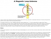
 Demonstrates the construction of **magnetic loop antennas**, detailing both multi-turn and single-turn designs. It covers a 30-inch diameter multi-turn loop for 80 meters, based on a February 1996 QST article, and an octagon single-turn loop made from 15mm copper tube with a 4.8-meter circumference, operating from 7 MHz to 14 MHz. The document also presents a smaller 800mm diameter loop for 14 MHz to 28 MHz, emphasizing the importance of high-voltage tuning capacitors. Covers the design and construction of custom **butterfly capacitors** and piston capacitors, including a split stator capacitor with 140 pF capacitance and a 6000 Volt rating, and a butterfly capacitor with 5-65 pF and 7200 Volt rating. It explains why butterfly capacitors are preferred over split stator types for high power applications due to lower losses and direct series connection of rotors, reducing resistive losses from wiper contacts. Material recommendations include clear PVC for plates and brass or stainless steel for non-magnetic hardware. Addresses practical considerations such as feeding the loop with a shielded 1/5 Faraday loop made from RG213 or RG8 coax, achieving VSWR 1.1 across bands, and optimizing its placement 180° from the capacitor. It also discusses mechanical joint resistance, dissimilar metal oxidation prevention using Vaseline, and a simple method for determining radiation angle with a TL-light tube. The guide includes diagrams for rotor, stator, and end plate construction.
 -
 Build your mobile antenna which outperforms Hustler by 10db and ATAS-100 by 18db. From 80 to 10m. The HB9ABX mobile HF antenna, designed for 10 to 80 meters, was developed by Felix Meyer and outperforms commercial antennas like HUSTLER and YAESU ATAS-100/120 in field tests. Made from fiberglass rods and enamelled copper wire, it includes a loading coil with adjustable taps for tuning across bands. Installation requires solid grounding, and adjustments are made via whip length and coil settings. An antenna tuner ensures optimal SWR. Users must handle fiberglass with care due to health risks. This design proved highly effective in South America and Europe.
 -
 The boomless quad antenna is a unique design that offers versatility for amateur radio operators. This antenna consists of two half-wave dipoles arranged in a square or circular shape, allowing for both vertical and horizontal polarization depending on the feed point. The design facilitates easy installation and rotation, making it suitable for various operating conditions. The construction utilizes strong materials, such as bamboo, and incorporates waterproofing techniques to enhance durability. This project outlines the necessary dimensions and materials, including copper wire and insulators, to successfully build the antenna. It emphasizes the importance of tuning each radiator element for optimal performance. The boomless quad is particularly effective across multiple HF bands, including 14 MHz, 21 MHz, and 28 MHz. By following the detailed instructions, operators can achieve a reliable and efficient antenna setup that enhances their DXing and contesting capabilities.
 -
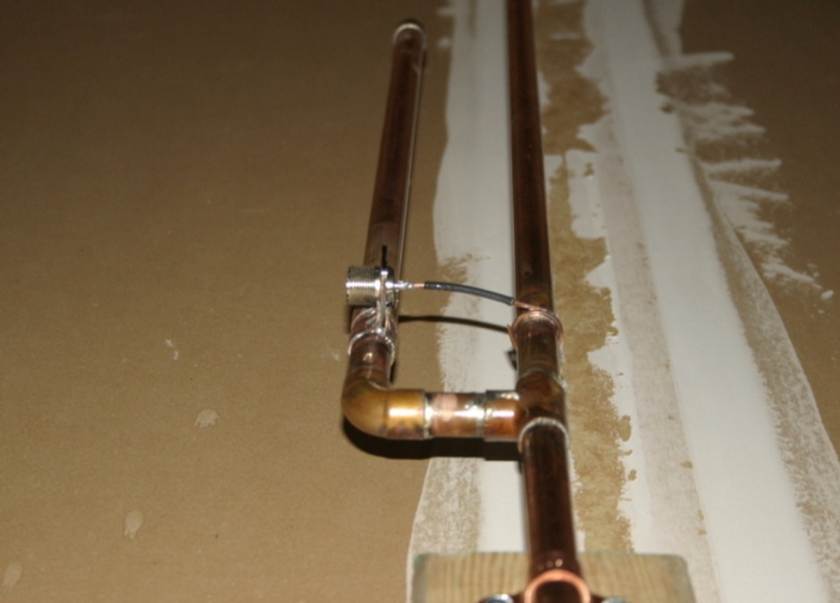
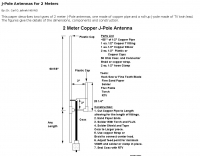 The page describes two types of 2 meter J-Pole antennas, one made of copper pipe and a roll-up J-pole made of TV twin lead, providing dimensions, components, and construction details. It is authored by Dr. Carl O. Jelinek N6VNG.
 -
 Here is a 70cm (440 Mhz) J-Pole antenna that is inexpensive, and easy to build. Author use 1/2 inch copper pipe, and the associated fittings necessary. The dimensions aren't typical however, this is what it took to get its SWR low.
 -
 2 meters copper tube antenna, tested with an Icom IC-V8000
 -
 This article describes how to make a quadrifilar helix (QFH) antenna easily, from inexpensive materials: uPVC plumbing pipe and RG-58U co-axial cable. A low-cost, easy-to-build Quadrifilar Helix (QFH) antenna for weather satellite reception using uPVC plumbing pipe and RG-58U coaxial cable. Unlike traditional designs requiring copper pipe and plumbing skills, this approach enables construction with basic tools and minimal technical expertise. The antenna's shorter, wider proportions favor higher elevation angles, reducing interference from horizon-level pager transmitters. Electrical connections are simplified at the antenna's apex, with the coaxial cable forming the radiating elements. Testing demonstrated consistent signal strength throughout satellite passes, proving effective weather satellite reception is achievable without precision engineering to sub-millimeter tolerances.
 -
 Types of beverage wires, choose best supports and insulators, multiple antennas at one feedpoint, all well documented with photos and exaustive explanation. This article offers insights on building Beverage antennas for optimal reception. Key takeaways include using strong wire (copperweld or electric fence), proper termination, and a good grounding system (multiple copper rods). The author recommends maximizing antenna length and orienting it towards desired stations. For best results, utilize an antenna tuner and experiment with termination resistors.
 -
 Conejo Valley Amateur Radio Club, article edited by Rory Eikland, KG6HCU and Ken Larson, KJ6RZ, they have had excellent experience building and using J-Pole antennas, and share their experience on planning VHF and UHF Jpole antennas.
 -
 This drawing shows a simple 10 meter wire J-pole antenna designed for 28.4 MHz. It is a vertical, end-fed Zepp-style antenna made from common materials and intended for easy home construction. The main radiating element is a straight length of stranded copper wire, either 14 or 18 gauge, cut to about 16.5 feet. At the top, the wire is supported by an insulator, allowing the antenna to be hoisted vertically. The matching section is made from 450-ohm ladder line, approximately 7 feet 9.5 inches long, and shorted at the bottom. This matching stub transforms the impedance so the antenna can be fed with coaxial cable. The feed point is tapped about 6 inches above the bottom of the stub, with the shield and center conductor connected at the proper points. A choke balun is formed with five turns of RG-58 coax in a 4-inch diameter loop to help reduce unwanted RF on the feed line. The drawing notes that this antenna has about 0 dBd gain, similar to a dipole, but offers an omnidirectional pattern and low-angle radiation when installed high. Its main advantage is practical performance, simple construction, and effective coverage for 10 meter operation.
 -
 Homebrew a j-pole 2mt and 70 cm antenna project. Make it cheap. This article includes homebrewing instructions, parts lists, tools needed and printable documentation.
 -
 The resource provides detailed information about a five-band indoor magnetic loop antenna designed for amateur radio operators. This antenna is capable of operating on the 20, 17, 15, 12, and 10 meter bands, making it a versatile choice for various HF communications. Constructed from a single 3-meter length of 22 mm copper tube, the design emphasizes compactness and efficiency, which is particularly beneficial for operators with limited space. The page includes insights into the construction process, tuning, and operational tips, catering to both novice and experienced users. In addition to the technical specifications, the resource also discusses the advantages of using a magnetic loop antenna indoors, such as reduced interference and improved performance in urban environments. It serves as a practical guide for those interested in building their own antenna, offering a straightforward approach to antenna design and construction. Overall, this resource is a valuable addition to the toolkit of amateur radio enthusiasts looking to enhance their station with an effective indoor antenna solution.
 -
 A simple dual band VHF UHF jpole antenna Projects by Dale Kubichek
 -
 Demonstrates the construction and performance of an updated ZS6BKW multiband dipole, a variant of the _G5RV_ antenna, specifically designed for HF operation. The article details a real-world installation using 13.5m copper wire elements and 12.2m of 450 Ohm ladder line, configured as a sloping inverted-V with the apex at 10m and ends at 4m above ground. It covers the critical aspect of impedance matching, incorporating an 8-turn choke balun at the feedline transition to RG-58U coax to mitigate RF common mode current. Measurements confirm favorable SWR readings below **1.3:1** on 7.1 MHz, 14.11 MHz, 18.06 MHz, and 24.8 MHz, indicating effective resonance across 40m, 20m, 17m, and 12m bands. The installation also shows usable SWR dips on 3.55 MHz (5:1), 29.02 MHz (2:1), and 50.84 MHz (3:1), extending its utility to 80m, 10m, and 6m with an antenna tuning unit. Initial on-air results report clear reception of stations over **5000km** away, validating its DX potential.
 -
 Selecting an appropriate antenna system for shortwave broadcasting involves evaluating various types based on performance, cost, and operational parameters. This resource details the critical specifications for broadcast antennas, including average and peak power ratings, directivity, takeoff angle (TOA), horizontal beamwidth, and gain, emphasizing that a 100-kW transmitter requires an antenna rated for 150 kW average and 400 kW peak. It clarifies that low TOA signals travel thousands of kilometers, while high TOA is for local coverage, and nearly all modern shortwave broadcast antennas are horizontally polarized. The article explores specific antenna types, such as Log-Periodic Antennas (LPAs), which offer wide frequency ranges (e.g., 2-30 MHz) and directional patterns with 11 dBi gain, costing from $20K to over $100K for multi-curtain versions. Dipole arrays, also known as curtain antennas, are prevalent in international broadcasting, featuring steerable beams (±15° and ±30°) and mode-switching capabilities to alter TOA, with high/low pairs costing over $1 million. Fan dipoles are noted for omnidirectional patterns, smaller size, and lower cost for low-power applications, while rhombics, though simple, require resistive termination and incur several dB of I2R losses. Balun considerations are crucial, as most communications baluns are not rated for the higher average and peak powers of AM broadcast transmitters. Modern shortwave antennas utilize durable materials like Alumoweld wire rope for radiators and support elements, avoiding copper, fiberglass, or materials prone to stretching or deterioration. Feeder systems for high-power stations often require tapered-line baluns to convert 50-ohm unbalanced power to 300-ohm balanced for connection to the antenna.
 -
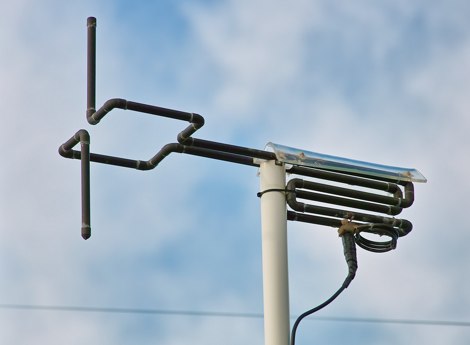
 This article describes the construction of a Moxon rectangle antenna for the 70MHz (4-meter) amateur radio band. This compact two-element beam design features folded element ends, reducing its width to approximately 75% of a half-wavelength. The antenna was built using enamelled copper wire stretched over a lightweight fiberglass kite spar frame, with a direct coaxial cable feed connection. Initial testing showed a VSWR of around 1.3 with distinct nulls at 90 degrees when horizontally mounted. The author later tested vertical polarization and suggested that the antenna's compact size might allow for indoor loft installation.
 -
 A 10-meter J-Pole antenna, detailed in QST February 1950, offers a straightforward solution for hams operating with restricted space. This design, originally presented by W1BLR, is a **half-wave radiator** fed by a quarter-wave matching stub, providing a low-angle radiation pattern beneficial for DX. The article describes building the antenna from readily available materials like copper pipe, emphasizing its simplicity and effectiveness for **single-band operation**. The J-Pole's inherent design provides a good impedance match to 50-ohm coaxial cable without the need for an external tuner, a significant advantage for portable or minimalist stations. Its nondirectional pattern ensures coverage in all directions, making it a versatile choice for general operating on the 28 MHz band. The construction plans are clear, allowing even those with basic workshop skills to assemble a functional antenna.
 -
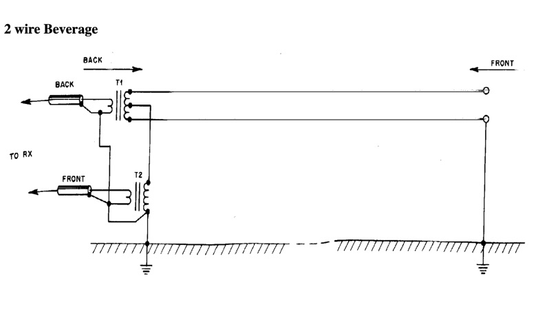 So you want to build a Beverage Antenna. This article offers insights on building a two-wire Beverage antenna for better reception. Key points include using long wire (at least a wavelength, ideally two), keeping it straight and away from vertical conductors, and sloping ends for noise reduction. The author recommends copper clad wire and mentions transformer design considerations for later discussion.
 -
 All copper J-Pole antennas for sale. 6 meter, 2 meter, 222 MHz, 440 MHz, LPFM, Marine, GMRS. Includes a construction plan in pdf format if you wish to build your own antenna.
 -
 F6EZX presents a detailed account of constructing a compact, multi-band _Levy antenna_ for portable holiday operations, specifically addressing issues with local QRM from a previous _Deltaloop_ setup. The article outlines the design criteria, including multi-band operation on 40m, 30m, 17m, 15m, 12m, and 10m, a symmetrical configuration to reduce interference, and a low take-off angle for DX. Construction involves 2x 10.3m radiating elements and a 15.3m open-wire feeder (ladder line) with 7cm spacing, made from 1.5mm2 copper wire and foam pipe insulation spacers. Theoretical calculations, referencing F9HJ's "_Les antennes Levy_" book, guide the determination of element lengths and feeder impedance characteristics, aiming for a good match across bands with a commercial antenna tuner. Initial field tests with the _VCI Vectronics VC300DLP_ tuner showed a 1:1 SWR from 80m to 10m, with some difficulty on 17m. The antenna, mounted as a 45-degree slopper with the high point at 12m, successfully facilitated DX contacts to South America, particularly Chile and Argentina, suggesting a lower take-off angle compared to the previous Deltaloop which favored Brazil. The Levy antenna significantly reduced TVI/RFI, attributed to its improved symmetry and greater distance from the QRA. While signal reports on 15m and 20m were 1-2 S-points lower than the Deltaloop, its performance on 40m and 30m was comparable, fulfilling the design goals for a portable, low-cost, multi-band solution.
 -
 WA2UGT X-beam antenna for 17 meters band
 -
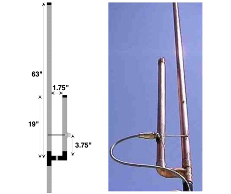
 Constructing a **2-meter** J-pole antenna from readily available copper plumbing components offers a robust and cost-effective solution for VHF operation. This design, dubbed the "Plumber's Delight," functions essentially as a half-wave dipole fed by 50-ohm coax via a **gamma match**. It incorporates a quarter-wave copper tubing support, which, when affixed to a metal mast or tower, enhances forward power in the direction of the radiating elements. The original configuration utilized a small ceramic trimmer capacitor for the gamma match, suitable for up to 10 watts. A subsequent modification replaced this with a 50 pF variable capacitor housed in a plastic enclosure, accommodating higher RF power and improving weather resistance. The antenna elements are secured using a copper "T" fitting, and an SO-239 connector mounts directly to this fitting. Performance includes gain away from the support mast, and tuning is straightforward by adjusting the gamma match capacitor for a 1:1 SWR. The total cost for materials, excluding the capacitor and coax, can be under $10.
 -
 A 2-meter Turnstile antenna, detailed for amateur satellite communication, offers a straightforward build for those looking to engage with orbiting transponders. The author, WB8ERJ, shares his personal design and construction methods, emphasizing the antenna's simplicity and effectiveness for LEO (Low Earth Orbit) satellite work. This design provides a circularly polarized signal, crucial for mitigating _Faraday rotation_ and signal fading often encountered with linearly polarized antennas when tracking satellites. Construction involves readily available materials like PVC pipe and copper wire, making it an accessible project for many hams. The article includes practical advice on element spacing and feed point considerations, drawing from the author's hands-on experience in the shack and field. It highlights the antenna's utility for receiving signals from various amateur satellites, including the popular AO-91 and AO-92. The Turnstile's inherent omnidirectional pattern in the horizontal plane, combined with its circular polarization, yields consistent signal reception, often resulting in **stronger decodes** and **more reliable contacts** compared to basic dipoles or verticals.
 -
 Constructing an HF End-Fed Half-Wave (EFHW) vertical antenna, the resource details the winding of a monoband matching unit, inspired by _AA5TB_, designed to provide a 50 Ohm impedance match without a ground plane or antenna tuner. It specifies the use of a _T200-2_ ferrite core for the transformer, outlining the 13-turn secondary and 2-turn primary winding process with enamelled copper wire. The document also describes the integration of a coax capacitor, whose length is critical for tuning and varies by band, with specific starting lengths provided for 20m, 17m, 15m, 12m, and 10m operation. The practical application section guides the builder through tuning the antenna using an antenna analyzer, emphasizing the iterative process of spacing secondary windings and trimming the coax capacitor to achieve resonance at the desired band frequency. It highlights the antenna's low angle of radiation, beneficial for DX, and claims up to 2 S-points improvement over a _G5RV_ or similar doublet when used as an omnidirectional vertical. A comprehensive shopping list, including specific part numbers from _Rapid Electronics_, is provided, along with advice on selecting fiberglass fishing poles for support and suitable antenna wire.
 -
 Autotena, a Taiwanese manufacturer, offers a diverse product line focused on RF communication antennas and related accessories. The resource details various antenna types, including **4G/3G LTE wideband high-gain low-profile antennas**, land mobile wideband antennas, fiberglass omnidirectional designs, and GPS mobile and marine antennas. Specific amateur radio offerings include NMO VHF load coil gain antennas, VHF whip gain antennas with PL-259 connectors, and UHF NMO mount antennas with 3dB/5dB gain. The company also produces antennas for CB and 10-meter amateur bands, such as aluminum broadband 26-30MHz antennas and big copper coil broadband 26-30MHz antennas. Additionally, the site showcases **RF amplifiers** for CB, HF, VHF, and UHF bands, including professional-grade base station amplifiers with 100% EIA duty cycle. Handheld antennas, PL-259 type mobile antennas, magnet mount antennas, and external CB speakers are also presented, alongside various mounting kits and cable assemblies.
 -
 This PDF document, authored by KT4QW in October 2004, details the construction and modeling of a dual-band, horizontally polarized hanging rectangular loop antenna for **10 and 17 meters**. The design, adapted from *The ARRL Handbook*, utilizes _NEC4WIN95_ software for scaling and optimization, targeting a 50 ohm feedpoint impedance. The resource includes a bill of materials, step-by-step construction instructions, and a discussion of the antenna's radiation characteristics. It presents NEC-generated elevation and azimuth patterns, comparing the loop's performance to a half-wave horizontal dipole at the same height and frequency. The 17-meter element is centered at 18.140 MHz for low SWR across the phone band, while the 10-meter element is centered at 28.500 MHz. Construction involves 14-gauge stranded copper wire and Schedule 40 PVC spreaders, with the total wire length calculated by the formula: Length in feet = 1005/MHz. The feedpoint impedance can be adjusted by modifying the rectangular aspect ratio. The document specifies hoisting the antenna to at least a half-wave above ground for testing. It notes that a balun was tested and found to have no measurable effect on SWR or radiation characteristics. A 2-meter scale model is presented to illustrate the physical design, and a "rotator" string is incorporated for directional adjustment up to 90 degrees.
 -
 The octoloop antenna is a length of 25 pair telephone wire inside an octagonal loop shield of 3/4 hard copper pipe
 -
 Easy home brew 2 meter copper jpole antenna build - under 20 bucks - Hits repeaters 45 miles away. Parts used bought at home depot build time 1 hour.
 -
 Pictures of a 2 meter, 220, 440 copper J-Pole antennas
 -
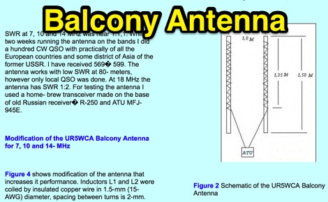 A project for a balcony antenna that works on 7 10 14 MHz made by 2 PVC tubes coiled with insulated copper wire, a solution for restricted lots.
 -
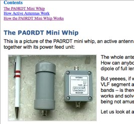 An Active antenna designed for VLF and shortwave radio reception. A small antenna capable of excellent performances on low bands, made on a copper plate and introductio to active antennas.
 -
 A 90-foot vertical antenna constructed from **aluminum irrigation tubing** is detailed, focusing on its innovative raising and lowering mechanism. The resource describes a **45-foot ginpole** system, allowing a single operator to erect or lower the antenna in minutes. It covers the mechanical design, including the pivot base, insulated joints for the tubing sections, and guy wire attachment points. The antenna consists of two 30-foot sections of 4-inch tubing and one 30-foot section of 2-inch tubing, stacked with the smaller diameter at the top. The electrical design incorporates PVC "condulet" boxes at the 30-foot and 60-foot points, housing relays to change the effective height for multi-band operation on 160, 80, 40, and 30 meters. Ferrite rod inductive chokes are used for DC control and to tune out gap capacitance. The antenna is fed with 1000 feet of open wire line, connected to a matching transformer comprising stacked toroids and a coaxial/toroidal balun. Grounding is achieved with a 3x3 foot grid of 16-gauge tinned copper wires with soldered crossovers.
 -
 A copper pipe Hentenna for 144 MHz. The Hentenna, a compact, high-gain loop antenna developed in Japan in the 1970s, offers approximately 5.1 dBd gain, comparable to a three-element Yagi. Adapted for 2 meters, it is crafted from copper pipe for simplicity, affordability, and broadband performance. Requiring no feed-point tuning, its construction involves soldering standard copper fittings. Installation demands non-conductive materials to minimize signal disruption. Versatile for vertical or horizontal polarization, it is ideal for FM, repeater, SSB, or CW applications. This design emphasizes practicality and performance for amateur radio enthusiasts
 -
 This antenna consists of 4 resonate dipoles made from 12 insulated copper electrical wire. The dipoles are resonate on the following bands: 6 meters, 10 meters, 12 meters and 17 meters.
 -
 Presents a detailed construction guide for a **Quadrifilar Helix Antenna** (QHA) optimized for 137 MHz, specifically for receiving weather satellite transmissions. The resource outlines the author's experience building previous QHA designs, highlighting challenges with tuning and nulls, and then focuses on a refined design by John Boyer, documented by Steve Blackmore, which proved easier to build and yielded superior reception. The guide provides precise element dimensions, including 1.5m of 32mm PVC pipe for the mast and 8mm soft copper tubing for the helix elements. It specifies lengths for horizontal tubes (190mm, 90mm) and helix elements (903mm, 1002mm), along with instructions for drilling, assembly, and forming a **balun** by wrapping RG58 coax around the mast. The text emphasizes critical steps like ensuring elements are square and twisting in the correct direction to avoid phase issues. It includes references to original QST articles by Buck Ruperto (W3KH) and the WxSat program for decoding satellite transmissions, contextualizing the antenna's purpose. The article concludes with a sample NOAA 12 image from September 1998, demonstrating the antenna's reception capabilities.
 -
 This article describes a loop usable from 7 - 21 mHz, using half inch copper tube 3 feet in circumference
 -
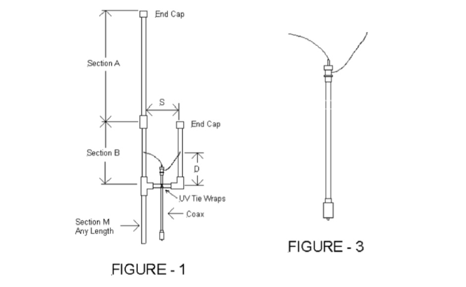
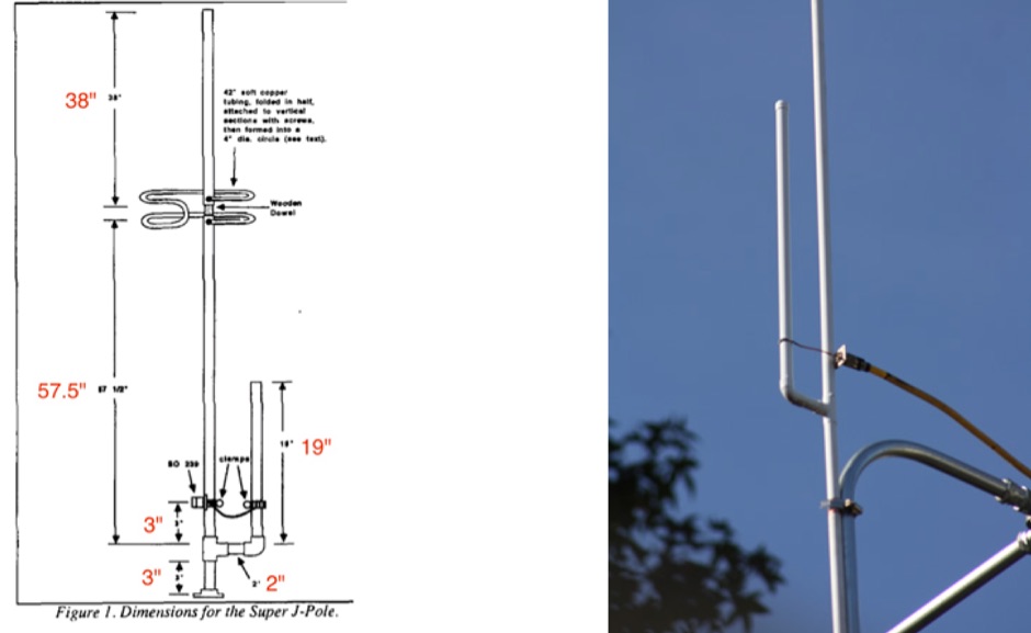
 Plans and drawings of common amateur radio antennas, like jpoles, copper cactus, super jpole, omnidirectionals and quads
 -
 One specific challenge in the KazShack, operating Single Operator Two Radios (SO2R), involved sharing a K9AY receive antenna between two transceivers without direct RF connection or manual feedline swapping. The solution, detailed in this project, adapts the **W3LPL RX bandpass filter** design to split 160m and 80m signals, feeding them to separate radio inputs while maintaining isolation. This approach also addresses the issue of strong broadcast band interference from a nearby 50KW WPTF transmitter on 680kc. The construction utilizes T-50-3 toroids and NP0 ceramic capacitors, built in a "dead bug" style on copper clad board. Each band's filter coils are identical and resonated to the desired frequency using an MFJ-259 antenna analyzer. A single DPDT relay, controlled by a remote toggle switch mounted on an aluminum panel, facilitates quick band switching between radios, simplifying low-band operations. While some signal loss is noted, the expected lower noise levels from the receive antenna are anticipated to compensate, potentially reducing the need for constant volume adjustments during toggling between transmit and receive antennas.
 -
 A 2 meter antenna made of copper tubes, offering circular polarization
 -
 A monoband J pole antenna dimensions sheet by N6JSX
 -
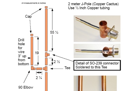
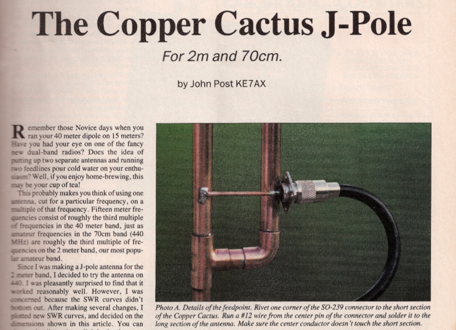 Original article published on February 1992 on 73 Amateur Radio Today about the 2m and 70 cm copper cactus J-pole antenna
 -
 A J-pole antenna plan made using a half inch copper tubing
 -
 An home made vertical dipole antenna made with simple material. The antenna has a total length of aproximately 16 feet. In this article appeared on June QST 2019, the author explain how he reached the optimal confirugation changing and adjusting the lower part of the antenna, trimming and spacing correctly the copper wire. PDF File to downloas
 -
 Optimizing a G5RV or ZS6BKW multiband wire antenna for HF operation often involves addressing common SWR issues and understanding feedline characteristics. This resource chronicles the construction and performance evaluation of a G5RV, initially built for 80m, 40m, 15m, and 10m bands, by a newly licensed Foundation operator. The author details the selection of materials, including 3.5 mm stainless steel wire for the doublet arms and enameled copper wire for the open-wire feeder, and the initial decision to omit a balun based on common online information. The narrative highlights the initial disappointing performance, characterized by high receive noise and poor signal reports on 80 meters, despite the transceiver's internal ATU achieving a 1:1 match. This led to experimentation with a coax current balun and further research into G5RV myths, such as SWR claims and the necessity of a balun. The author then describes modifying the antenna to the ZS6BKW configuration, which involves specific changes to the doublet and feedline lengths, and integrating a 1:1 current balun wound on a ferrite toroid. The modifications resulted in improved reception and transmit performance across the bands.
 -
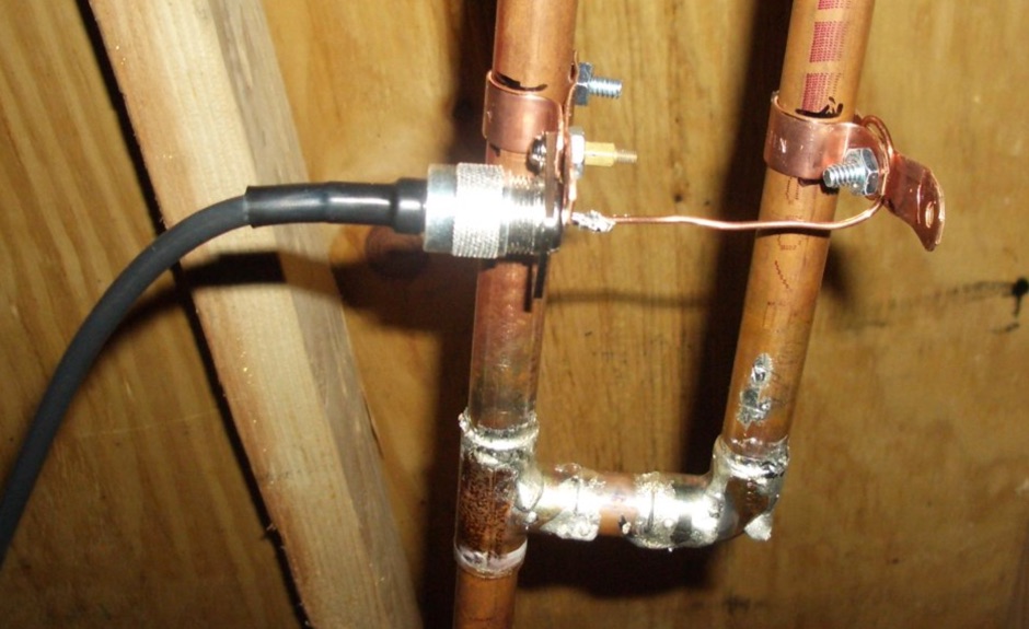
 Single Coax Feed to Multi-Band Copper Cactus Antenna.
 -
 One point eight MHz to 30 MHz is the operational bandwidth for this 4:1 Ruthroff voltage balun, designed to interface an unbalanced T-Match network with a balanced antenna system. The project details the construction using a _T200-2_ powdered iron toroid core, tightly wrapped in PVC electrical tape for insulation, and wound with 17 double bifilar turns of 1.25mm enamelled copper wire. This outboard balun offers flexibility, allowing hams to trial various baluns based on antenna system and impedance characteristics, rather than integrating it directly into the tuner. The resource includes a schematic of the balun, a wiring diagram showing winding connections, and a table suggesting alternative toroid cores like the T80-2 or T400-2 with corresponding winding counts. Component sourcing is straightforward, listing items such as the _Amidon_ T-200-2 core, SO-239 connector, and a sealed polycarbonate enclosure from Jaycar. Performance evaluation was conducted using an _AIM 4170C_ antenna analyser, demonstrating efficient 1:4 voltage transformation across the specified HF spectrum. Further efficiency tests involved measuring RF power loss at various frequencies, revealing minimal loss—less than 0.7 dB from 3.6 MHz to 30 MHz, and only 2.0 dB at 1.8 MHz. These measurements, performed under ideal 50-ohm conditions, confirm the balun's effectiveness as a low-loss interface for multi-band antenna systems. The page also links to several other balun and unun projects, including 1:1 current and voltage baluns, and 9:1 voltage ununs, providing a broader context for impedance matching solutions.
 -
 The ZS6BKW multiband antenna, an optimized variant of the classic G5RV, features a 102-foot (31.1 m) horizontal span and a 39.1-foot ladder line matching section. This design, derived by G0GSF (formerly ZS6BKW) in the early 1980s using computer programs and _Smith charts_, aims for improved SWR across multiple HF bands compared to its predecessor. Construction details specify Wireman 554 ladder line and #14 AWG THHN copper wire for the radiators, with precise instructions for determining the velocity factor (VF) of the ladder line using an antenna analyzer or dip meter, ensuring accurate physical length for the matching section. The radiator length is electrically 1.35 wavelengths for the 20-meter band, requiring careful trimming during tuning. Field measurements with an _AIM-4170C_ analyzer by KI4PMI and NC4FB demonstrated good SWR curves and bandwidth on 6, 10, 12, 17, 20, and 40 meters. The antenna was deemed unusable on 15 and 30 meters due to very high SWR, but an LDG AT-100PRO autotuner successfully brought 6 and 80 meters into tune. Contacts were made on 80, 40, 20, and 17 meters, including a **17-meter** contact to Spain. EZNEC models for 80-6 meters are provided, along with an AutoEZ model by AC6LA, which predicted good SWR for 80-10 meters. W5DXP's modifications for an all-band HF ZS6BKW are also referenced.