Search results
Query: copper j pole antenna
Links: 51 | Categories: 0
-
 A home made J-Pole antenna for 50 MHz. This article describes how to build a J-Pole antenna for the 6-meter amateur radio band. It's a good choice for those who want an antenna with better performance than a simple wire dipole, but at a lower cost than buying a commercial antenna. The project requires soldering copper pipes and some specific materials, but can be built in a day
 -
-
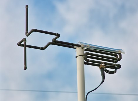
 The boomless quad antenna is a unique design that offers versatility for amateur radio operators. This antenna consists of two half-wave dipoles arranged in a square or circular shape, allowing for both vertical and horizontal polarization depending on the feed point. The design facilitates easy installation and rotation, making it suitable for various operating conditions. The construction utilizes strong materials, such as bamboo, and incorporates waterproofing techniques to enhance durability. This project outlines the necessary dimensions and materials, including copper wire and insulators, to successfully build the antenna. It emphasizes the importance of tuning each radiator element for optimal performance. The boomless quad is particularly effective across multiple HF bands, including 14 MHz, 21 MHz, and 28 MHz. By following the detailed instructions, operators can achieve a reliable and efficient antenna setup that enhances their DXing and contesting capabilities.
 -
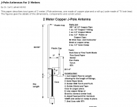 The page describes two types of 2 meter J-Pole antennas, one made of copper pipe and a roll-up J-pole made of TV twin lead, providing dimensions, components, and construction details. It is authored by Dr. Carl O. Jelinek N6VNG.
 -
 Here is a 70cm (440 Mhz) J-Pole antenna that is inexpensive, and easy to build. Author use 1/2 inch copper pipe, and the associated fittings necessary. The dimensions aren't typical however, this is what it took to get its SWR low.
 -
 Conejo Valley Amateur Radio Club, article edited by Rory Eikland, KG6HCU and Ken Larson, KJ6RZ, they have had excellent experience building and using J-Pole antennas, and share their experience on planning VHF and UHF Jpole antennas.
 -
 This drawing shows a simple 10 meter wire J-pole antenna designed for 28.4 MHz. It is a vertical, end-fed Zepp-style antenna made from common materials and intended for easy home construction. The main radiating element is a straight length of stranded copper wire, either 14 or 18 gauge, cut to about 16.5 feet. At the top, the wire is supported by an insulator, allowing the antenna to be hoisted vertically. The matching section is made from 450-ohm ladder line, approximately 7 feet 9.5 inches long, and shorted at the bottom. This matching stub transforms the impedance so the antenna can be fed with coaxial cable. The feed point is tapped about 6 inches above the bottom of the stub, with the shield and center conductor connected at the proper points. A choke balun is formed with five turns of RG-58 coax in a 4-inch diameter loop to help reduce unwanted RF on the feed line. The drawing notes that this antenna has about 0 dBd gain, similar to a dipole, but offers an omnidirectional pattern and low-angle radiation when installed high. Its main advantage is practical performance, simple construction, and effective coverage for 10 meter operation.
 -
 Homebrew a j-pole 2mt and 70 cm antenna project. Make it cheap. This article includes homebrewing instructions, parts lists, tools needed and printable documentation.
 -
 A simple dual band VHF UHF jpole antenna Projects by Dale Kubichek
 -
 Demonstrates the construction and performance of an updated ZS6BKW multiband dipole, a variant of the _G5RV_ antenna, specifically designed for HF operation. The article details a real-world installation using 13.5m copper wire elements and 12.2m of 450 Ohm ladder line, configured as a sloping inverted-V with the apex at 10m and ends at 4m above ground. It covers the critical aspect of impedance matching, incorporating an 8-turn choke balun at the feedline transition to RG-58U coax to mitigate RF common mode current. Measurements confirm favorable SWR readings below **1.3:1** on 7.1 MHz, 14.11 MHz, 18.06 MHz, and 24.8 MHz, indicating effective resonance across 40m, 20m, 17m, and 12m bands. The installation also shows usable SWR dips on 3.55 MHz (5:1), 29.02 MHz (2:1), and 50.84 MHz (3:1), extending its utility to 80m, 10m, and 6m with an antenna tuning unit. Initial on-air results report clear reception of stations over **5000km** away, validating its DX potential.
 -
 Selecting an appropriate antenna system for shortwave broadcasting involves evaluating various types based on performance, cost, and operational parameters. This resource details the critical specifications for broadcast antennas, including average and peak power ratings, directivity, takeoff angle (TOA), horizontal beamwidth, and gain, emphasizing that a 100-kW transmitter requires an antenna rated for 150 kW average and 400 kW peak. It clarifies that low TOA signals travel thousands of kilometers, while high TOA is for local coverage, and nearly all modern shortwave broadcast antennas are horizontally polarized. The article explores specific antenna types, such as Log-Periodic Antennas (LPAs), which offer wide frequency ranges (e.g., 2-30 MHz) and directional patterns with 11 dBi gain, costing from $20K to over $100K for multi-curtain versions. Dipole arrays, also known as curtain antennas, are prevalent in international broadcasting, featuring steerable beams (±15° and ±30°) and mode-switching capabilities to alter TOA, with high/low pairs costing over $1 million. Fan dipoles are noted for omnidirectional patterns, smaller size, and lower cost for low-power applications, while rhombics, though simple, require resistive termination and incur several dB of I2R losses. Balun considerations are crucial, as most communications baluns are not rated for the higher average and peak powers of AM broadcast transmitters. Modern shortwave antennas utilize durable materials like Alumoweld wire rope for radiators and support elements, avoiding copper, fiberglass, or materials prone to stretching or deterioration. Feeder systems for high-power stations often require tapered-line baluns to convert 50-ohm unbalanced power to 300-ohm balanced for connection to the antenna.
 -
 A 10-meter J-Pole antenna, detailed in QST February 1950, offers a straightforward solution for hams operating with restricted space. This design, originally presented by W1BLR, is a **half-wave radiator** fed by a quarter-wave matching stub, providing a low-angle radiation pattern beneficial for DX. The article describes building the antenna from readily available materials like copper pipe, emphasizing its simplicity and effectiveness for **single-band operation**. The J-Pole's inherent design provides a good impedance match to 50-ohm coaxial cable without the need for an external tuner, a significant advantage for portable or minimalist stations. Its nondirectional pattern ensures coverage in all directions, making it a versatile choice for general operating on the 28 MHz band. The construction plans are clear, allowing even those with basic workshop skills to assemble a functional antenna.
 -
 All copper J-Pole antennas for sale. 6 meter, 2 meter, 222 MHz, 440 MHz, LPFM, Marine, GMRS. Includes a construction plan in pdf format if you wish to build your own antenna.
 -
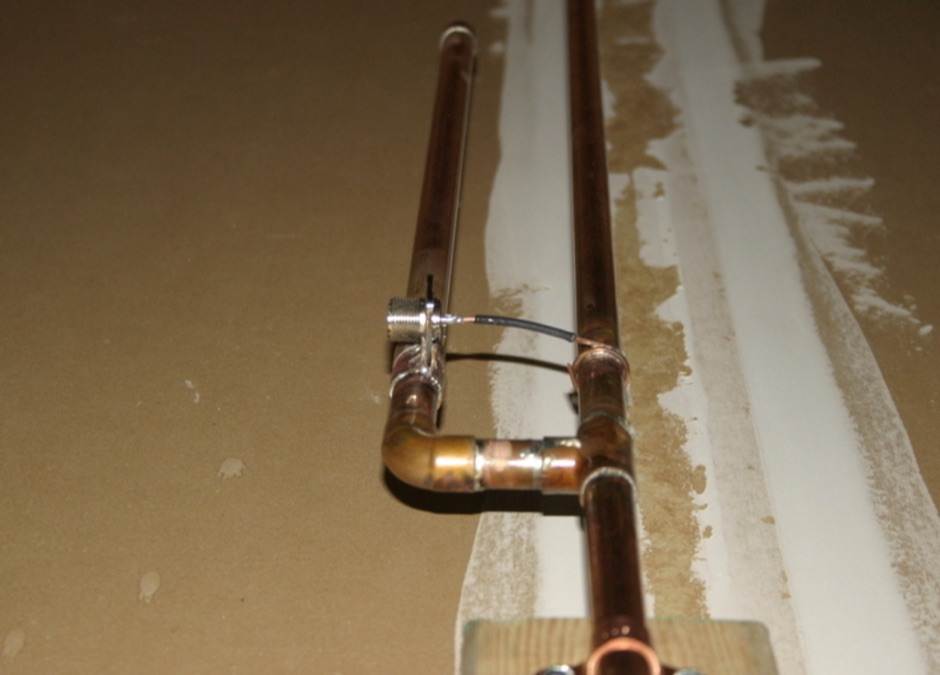
 Constructing a **2-meter** J-pole antenna from readily available copper plumbing components offers a robust and cost-effective solution for VHF operation. This design, dubbed the "Plumber's Delight," functions essentially as a half-wave dipole fed by 50-ohm coax via a **gamma match**. It incorporates a quarter-wave copper tubing support, which, when affixed to a metal mast or tower, enhances forward power in the direction of the radiating elements. The original configuration utilized a small ceramic trimmer capacitor for the gamma match, suitable for up to 10 watts. A subsequent modification replaced this with a 50 pF variable capacitor housed in a plastic enclosure, accommodating higher RF power and improving weather resistance. The antenna elements are secured using a copper "T" fitting, and an SO-239 connector mounts directly to this fitting. Performance includes gain away from the support mast, and tuning is straightforward by adjusting the gamma match capacitor for a 1:1 SWR. The total cost for materials, excluding the capacitor and coax, can be under $10.
 -
 A 2-meter Turnstile antenna, detailed for amateur satellite communication, offers a straightforward build for those looking to engage with orbiting transponders. The author, WB8ERJ, shares his personal design and construction methods, emphasizing the antenna's simplicity and effectiveness for LEO (Low Earth Orbit) satellite work. This design provides a circularly polarized signal, crucial for mitigating _Faraday rotation_ and signal fading often encountered with linearly polarized antennas when tracking satellites. Construction involves readily available materials like PVC pipe and copper wire, making it an accessible project for many hams. The article includes practical advice on element spacing and feed point considerations, drawing from the author's hands-on experience in the shack and field. It highlights the antenna's utility for receiving signals from various amateur satellites, including the popular AO-91 and AO-92. The Turnstile's inherent omnidirectional pattern in the horizontal plane, combined with its circular polarization, yields consistent signal reception, often resulting in **stronger decodes** and **more reliable contacts** compared to basic dipoles or verticals.
 -
 Constructing an HF End-Fed Half-Wave (EFHW) vertical antenna, the resource details the winding of a monoband matching unit, inspired by _AA5TB_, designed to provide a 50 Ohm impedance match without a ground plane or antenna tuner. It specifies the use of a _T200-2_ ferrite core for the transformer, outlining the 13-turn secondary and 2-turn primary winding process with enamelled copper wire. The document also describes the integration of a coax capacitor, whose length is critical for tuning and varies by band, with specific starting lengths provided for 20m, 17m, 15m, 12m, and 10m operation. The practical application section guides the builder through tuning the antenna using an antenna analyzer, emphasizing the iterative process of spacing secondary windings and trimming the coax capacitor to achieve resonance at the desired band frequency. It highlights the antenna's low angle of radiation, beneficial for DX, and claims up to 2 S-points improvement over a _G5RV_ or similar doublet when used as an omnidirectional vertical. A comprehensive shopping list, including specific part numbers from _Rapid Electronics_, is provided, along with advice on selecting fiberglass fishing poles for support and suitable antenna wire.
 -
 This PDF document, authored by KT4QW in October 2004, details the construction and modeling of a dual-band, horizontally polarized hanging rectangular loop antenna for **10 and 17 meters**. The design, adapted from *The ARRL Handbook*, utilizes _NEC4WIN95_ software for scaling and optimization, targeting a 50 ohm feedpoint impedance. The resource includes a bill of materials, step-by-step construction instructions, and a discussion of the antenna's radiation characteristics. It presents NEC-generated elevation and azimuth patterns, comparing the loop's performance to a half-wave horizontal dipole at the same height and frequency. The 17-meter element is centered at 18.140 MHz for low SWR across the phone band, while the 10-meter element is centered at 28.500 MHz. Construction involves 14-gauge stranded copper wire and Schedule 40 PVC spreaders, with the total wire length calculated by the formula: Length in feet = 1005/MHz. The feedpoint impedance can be adjusted by modifying the rectangular aspect ratio. The document specifies hoisting the antenna to at least a half-wave above ground for testing. It notes that a balun was tested and found to have no measurable effect on SWR or radiation characteristics. A 2-meter scale model is presented to illustrate the physical design, and a "rotator" string is incorporated for directional adjustment up to 90 degrees.
 -
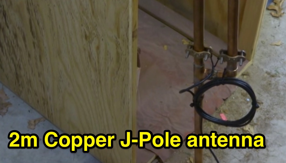
 Easy home brew 2 meter copper jpole antenna build - under 20 bucks - Hits repeaters 45 miles away. Parts used bought at home depot build time 1 hour.
 -
 Pictures of a 2 meter, 220, 440 copper J-Pole antennas
 -
 A 90-foot vertical antenna constructed from **aluminum irrigation tubing** is detailed, focusing on its innovative raising and lowering mechanism. The resource describes a **45-foot ginpole** system, allowing a single operator to erect or lower the antenna in minutes. It covers the mechanical design, including the pivot base, insulated joints for the tubing sections, and guy wire attachment points. The antenna consists of two 30-foot sections of 4-inch tubing and one 30-foot section of 2-inch tubing, stacked with the smaller diameter at the top. The electrical design incorporates PVC "condulet" boxes at the 30-foot and 60-foot points, housing relays to change the effective height for multi-band operation on 160, 80, 40, and 30 meters. Ferrite rod inductive chokes are used for DC control and to tune out gap capacitance. The antenna is fed with 1000 feet of open wire line, connected to a matching transformer comprising stacked toroids and a coaxial/toroidal balun. Grounding is achieved with a 3x3 foot grid of 16-gauge tinned copper wires with soldered crossovers.
 -
 This antenna consists of 4 resonate dipoles made from 12 insulated copper electrical wire. The dipoles are resonate on the following bands: 6 meters, 10 meters, 12 meters and 17 meters.
 -
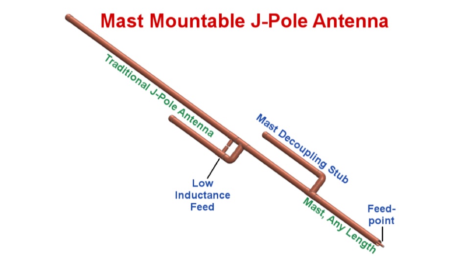
 Plans and drawings of common amateur radio antennas, like jpoles, copper cactus, super jpole, omnidirectionals and quads
 -
 A 2 meter antenna made of copper tubes, offering circular polarization
 -
 A monoband J pole antenna dimensions sheet by N6JSX
 -
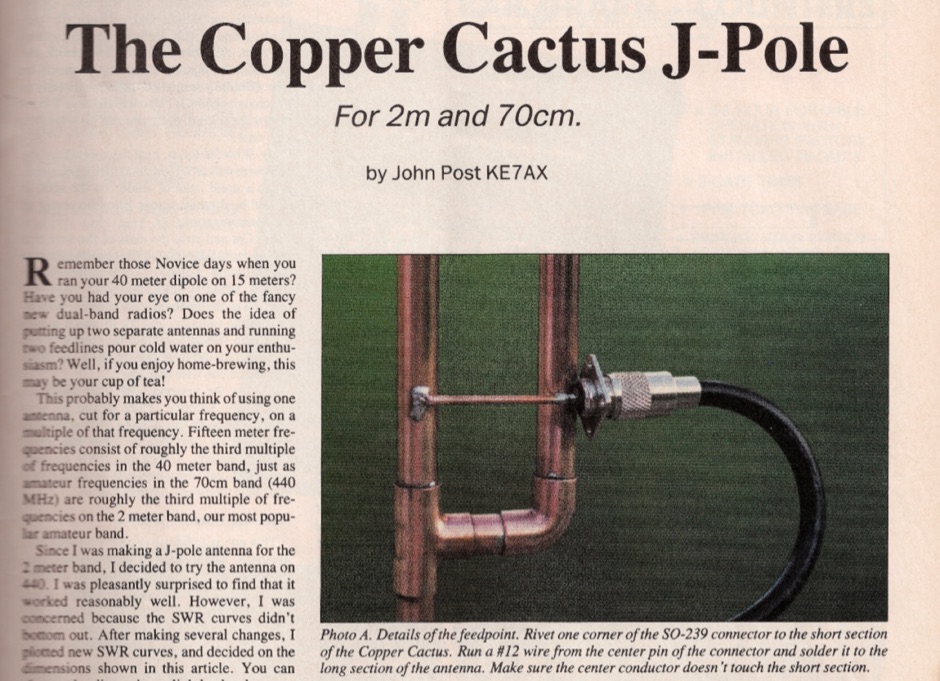 Original article published on February 1992 on 73 Amateur Radio Today about the 2m and 70 cm copper cactus J-pole antenna
 -
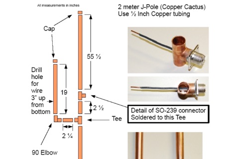 A J-pole antenna plan made using a half inch copper tubing
 -
 An home made vertical dipole antenna made with simple material. The antenna has a total length of aproximately 16 feet. In this article appeared on June QST 2019, the author explain how he reached the optimal confirugation changing and adjusting the lower part of the antenna, trimming and spacing correctly the copper wire. PDF File to downloas
 -
 This resource details the four primary functions of a ground system: lightning energy dispersion, equipment safety, RF return path provision for end-fed antennas, and management of induced RF currents. It clarifies that a ground system's effectiveness varies depending on its specific function, noting that a good lightning ground might not be an effective RF ground. The content emphasizes that proper antenna system design, including baluns and appropriate feedline lengths, often negates the need for an RF station ground to mitigate common mode currents or RFI in the shack. The article quantifies lightning energy, stating its peak is in the dozens or hundreds of kilohertz, with damaging energy extending to hundreds of megahertz, and currents reaching thousands of amperes. It recommends solid, wide, smooth copper surfaces for ground leads to achieve low impedance across a wide frequency range. The author, W8JI, shares practical insights from his station, which includes two 300-ft towers and four 130-ft wire verticals, detailing his use of common point grounds and _DX Engineering RR-8 HD_ antenna switches for lightning protection without coaxial surge protectors. Specific examples of antenna systems prone to common mode current problems are listed, such as random wire antennas without proper feedline lengths and off-center fed dipoles. The text also explains how a ground screen or radial system can reduce local noise sensitivity for vertically polarized antennas by covering the lossy earth.
 -
 An interesting article on how to make copper cactus J-Pole antennas
 -
 This is the construction of a copper cactus style j-pole antenna.
 -
 This web article by VK3BLG details the construction of an experimental 70cm (432 MHz) circularly polarized patch antenna, intended for satellite communication. The resource provides dimensions, feed point specifications, and impedance matching considerations for a single patch element, with discussion extending to array configurations for circular polarization. Construction involves a copper patch element on a dielectric substrate, fed via a coaxial cable. The design is based on information derived from AO-40 satellite antenna specifications, focusing on achieving circular polarization for satellite reception. The article includes specific dimensions for the patch and feed points, along with impedance values. Validation is implied through on-air satellite reception reports, with initial signal reports of **1 S-point above noise** for AO-40 beacons using a grid reflector, improving to **3-4 S-points above noise** with a 2-turn helical feed. The author references a _NanoVNA_ for impedance measurements and discusses the relationship between slot and dipole antennas in the context of patch design. DXZone Focus: Web Article | 70cm Patch Antenna | On-Air Satellite Reception | Circular Polarization
 -
 A eham article on a square copper dipole antenna for 50 MHz by K0FF
 -
 Demonstrates the construction and tuning of a **20-17-15 meter fan dipole** using 12-gauge PVC insulated copper wire and an Alpha-Delta C kit feedpoint. The project details the use of 14-inch pine dowels with 6-inch spaced holes to maintain wire separation for the parallel elements. Initial tuning was performed at shoulder height, with final adjustments made after elevation to 38 feet, accounting for frequency shifts observed between ground-level and elevated antenna positions. SWR analysis graphs are presented, showing performance below 1:3 across the entire 20-meter band, below 1:2 for 17 meters, and below 1:3 for 15 meters. The author notes significant RX improvements of +3 to +9 dB, occasionally exceeding +20 dB, compared to a commercial Alpha Delta DX LB Plus. The total hardware cost for this DIY antenna project was approximately $90, with the author emphasizing the utility of an **antenna analyzer** like the RigExpert AA54 for precise tuning. The fan dipole also exhibits tunable resonance on 12, 10, and 6 meters, though with reduced efficiency. Performance comparisons on 20 meters showed the fan dipole outperforming the Alpha-Delta on long-path north-south DX contacts.
 -
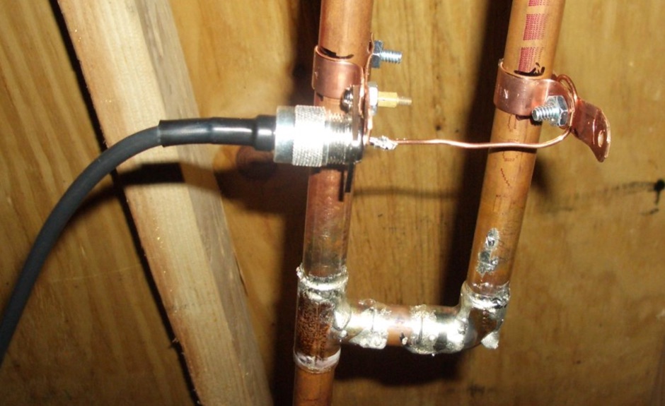
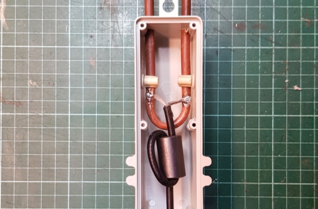
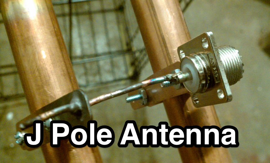 The copper J-Pole antenna soldered in a couple of hours with an interesting method to setup the feeding point
 -
 A moxon antenna for the 50 MHz build with 19 feet of 14 AWG copper wire, and based on a set of PVC pipes. This is an easy to build project that will give you an efficient directional antenna on 6 meters band with low SWR on more than 1 MHz bandwidth.
 -
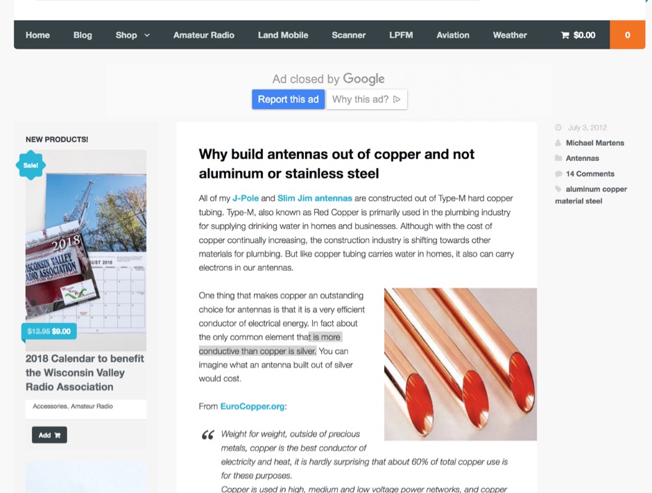 Why build antennas out of copper and not aluminum or stainless steel. Selecting the best metals for antennas evaluating the conductivity factor.
 -
 A homemade Jpole antenna for 70 cm band made with 6mm copper pipe
 -
 A homemade j-pole antenna for six meters band, designed to work on local repeaters, and working on the 52-53 MHz. Includes a list of needed materials and detailed description on assembling the copper tubes used to build this antenna.
 -
 The simple balcony vertical HF antenna made with plastic fishing pole. Just along the pole I install copper wire in 7 meter length. Then was installed ATU. It was used home brew tuner. For each band was used one counterpoise in length 0.8 x lambda/4
 -
 This J-Pole is mounted on a fishing rod. The radiator L1 is an isolated copper-wire with a length of 281,5 cm while the quarter-wave matching sector L2 is made with 450-Ohm-Wireman-cable
 -
 The video showcases the setup of a 300 MHz oscillator, a 100W radiofrequency amplifier, and a dipole antenna for transmitting radio waves, leading to the fluorescence of a nearby light bulb. It demonstrates the presence of standing waves on the dipole antenna and how intensity varies along its length. Additionally, the usage of a copper pipe as a receiving antenna is explored, showing changes in intensity depending on alignment and proximity to the transmitter. Finally, a B field antenna sensitive to magnetic fields is introduced, revealing brightness variations in different orientations. The video offers insightful observations on radio wave transmission and reception phenomena.
 -
 Building an End-Fed Half-Wave (EFHW) antenna from a kit, as detailed by Frank Bontenbal, PA2DKW, with process photos by Bob Inderbitzen, NQ1R, offers a practical approach for hams. This specific kit, a collaboration between ARRL and HF Kits, targets 10, 15, 20, and 40 meters, making it a versatile option for HF operations. Unlike a center-fed dipole, the EFHW is a half-wavelength antenna fed at one end, which simplifies deployment, particularly for portable use. The construction guide meticulously outlines the assembly of the 49:1 impedance matching network, crucial for transforming the antenna's high impedance (around 2,500 Ohms) to a transceiver-friendly 50 Ohms. Steps include preparing the enclosure by drilling holes for the coaxial connector and antenna connections, followed by the precise winding of enameled copper wire onto a toroid to create the transformer. The guide emphasizes careful insulation removal and soldering for reliable connections. Final assembly involves integrating a 100 pF capacitor for higher band compensation, soldering the transformer's primary and secondary sides, and conducting SWR tests with a 2K7 resistor or a half-wavelength wire. The document also provides examples of wire lengths for different bands, such as 16 feet for 10 meters or 66 feet for 40 meters, demonstrating the transformer's adaptability for various half-wavelength configurations.
 -
 A simple superheterodyne receiver (3.5–30 MHz) for amateur radio achieves stable SSB-CW reception using modern BJTs, an AD831 mixer, a 6-pole quartz filter, and Seiler oscillators. Designed with high IF (4.5 MHz), compact AM-FM variable capacitors, and modular resonant circuits, it ensures selectivity, image rejection, and stable tuning. Built in a copper-lined wooden case, it features practical assembly techniques but lacks advanced features like AGC or S-meter. Effective on basic antennas, it achieves global reception.
 -
 Dipole for 40m band. It is a simple linear loaded dipole feeded with 450-Ohm openwire feedline. Designed it for resonance at 7.050 MHz, can be tuned on 30m and 80m bands with an external antenna tuner. Build with simple electrical copper wire (2.5 mmq/13 awg) and two fishing poles with size of about 7 m/23 ft.
 -
 A small magnetic loop antenna, often employed by hams facing antenna restrictions or high local RFI, offers a compact solution for HF operation. This resource details the construction of a foldable magnetic loop designed for the 40m through 17m bands, emphasizing its high-Q factor and _Faraday coupling_ for effective noise rejection and narrow-band filtering. The guide outlines material selection, advocating for copper over aluminum to maximize efficiency, and provides insights into the physics governing its operation, including impedance matching and resonance principles. Practical application of this antenna design is particularly beneficial for QRP enthusiasts and portable operators seeking a stealthy, high-performance antenna. The construction process includes specific details for a 1-meter diameter loop, a 140pF variable capacitor, and a _gamma match_ for impedance transformation. Performance comparisons suggest that while a full-size dipole might offer slightly better gain, the magnetic loop's ability to mitigate local noise often results in a superior signal-to-noise ratio, making it a viable option for challenging RF environments.
 -
 This project outlines the construction of a simple TEFV (Tilted End-Fed Vertical) antenna suitable for backyard or park installations. The design requires basic materials such as 100 feet of coated stranded copper wire, wood stakes, metal ground rods, a non-conductive fiberglass pole, and essential tools like wire cutters and a soldering iron. The antenna is supported by a 20-33 feet tall pole and includes a 9:1 unun for impedance matching and a resistor for tuning. Step-by-step instructions guide the assembly, from preparing the wire and pole to connecting the unun and resistor, ensuring a functional and durable setup for outdoor use.
 -
 The Slim Jim VHF antenna, originally designed by G2BCX, is a folded half-wave dipole fed by a quarter-wave matching section. This version, built from a recycled professional aluminum dipole, demonstrates that various materials—such as copper, brass, or twin-lead—can be used. The article details the antenna’s construction, required materials, and tuning process, emphasizing mechanical stability and ease of assembly. With proper adjustment of the feed point, it provides excellent SWR across the band. Its durability and simplicity make it a practical and efficient VHF antenna solution.
 -
 A 13-foot total radiating element length is achieved by combining a Buddipole Long Telescopic Whip with 4 feet of modified tripod tubes, forming a low-profile, multiband antenna for **POTA** operations. The resource details the transformation of an Amazon Basics Aluminum Light Photography Tripod Stand, focusing on electrically isolating the top two radiating sections from the bottom support. John, VA3KOT, outlines component sourcing, including the 9-foot 4-inch fully extended whip, and emphasizes using adhesive copper tape for reliable electrical contact and conductive grease to prevent oxidation at tube connections. The construction process, while not requiring specialized tools, highlights careful assembly to ensure proper electrical conductivity and mechanical stability. The author's experience with this setup suggests its effectiveness for portable activations, offering a discreet profile compared to larger antenna systems. The design prioritizes ease of deployment and transport, making it a practical solution for operators seeking a compact yet versatile antenna for field use.
 -
 This project outlines a simple, cost-effective 40m band HF dipole antenna design, ideal for beginners. Constructed with insulated copper wire and a 1:1 balun, it offers a 50-ohm impedance, suitable for both 40m and 15m bands due to the harmonic relationship. Calculations account for a K factor, ensuring optimal length and performance. Antenna modeling with 4NEC2 confirms practical access to both bands, though real-world results may vary. Lightweight materials and straightforward assembly make it an accessible and versatile amateur radio solution.
 -
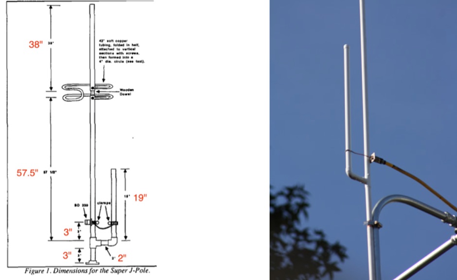
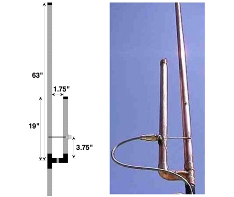
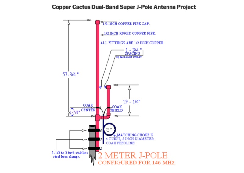 Details the construction of a Copper Cactus Dual-Band Super J-Pole Antenna, providing specific measurements for 1/2-inch copper tubing sections, including a 57-1/2-inch long section and a 19-inch short section, along with a 42-inch piece of 3/16-inch or 1/4-inch soft copper tubing for the matching stub. It covers soldering techniques for copper fittings, drilling an SO-239 panel mount coaxial fitting, and securing feed point connections with stainless steel adjustable band clamps. The resource specifies materials such as Schedule M 1/2-inch copper tubing, various copper fittings, a hardwood dowel or Fiberglas rod for insulation, and #14 stranded copper wire for the feed point. The guide simplifies the J-pole feed point by using an SO-239 fitting with an elongated mounting hole and band clamps, noting an optimal feed point distance of approximately 3 inches above the crossbar for proper impedance matching. It recommends a 4-turn coax choke, 5 inches in diameter, placed within 3 to 4 inches of the feed point for 2-meter operation to mitigate RF on the feedline. The project emphasizes weather sealing with silicon or butyl rubber compound and clear lacquer for durability and appearance.