Search results
Query: google ape
Links: 25 | Categories: 0
-
 SM0DTK's 40-meter Moxon antenna project details the construction and deployment of a wire Moxon rectangle, specifically dimensioned for the 7 MHz band. The resource outlines the use of a _Moxon Rectangle Generator_ for calculating wire lengths and the fabrication of plexiglass supports for corners and the feeding point. It describes the practical challenges of elevating the antenna to approximately **14 meters** using an aluminum tube and fiberglass rod, emphasizing the adjustment process for achieving the correct rectangular shape. The article presents comparative results against a 60-meter long-wire and a full-size 40-meter ground plane antenna. The Moxon demonstrated significant directional gain towards the west, facilitating DX contacts in the Caribbean with **100 watts**, while simultaneously reducing QRM from strong eastern European stations. The SWR was reported as perfect without the need for an antenna tuner, validating the design's effectiveness for targeted signal enhancement and interference mitigation.
 -
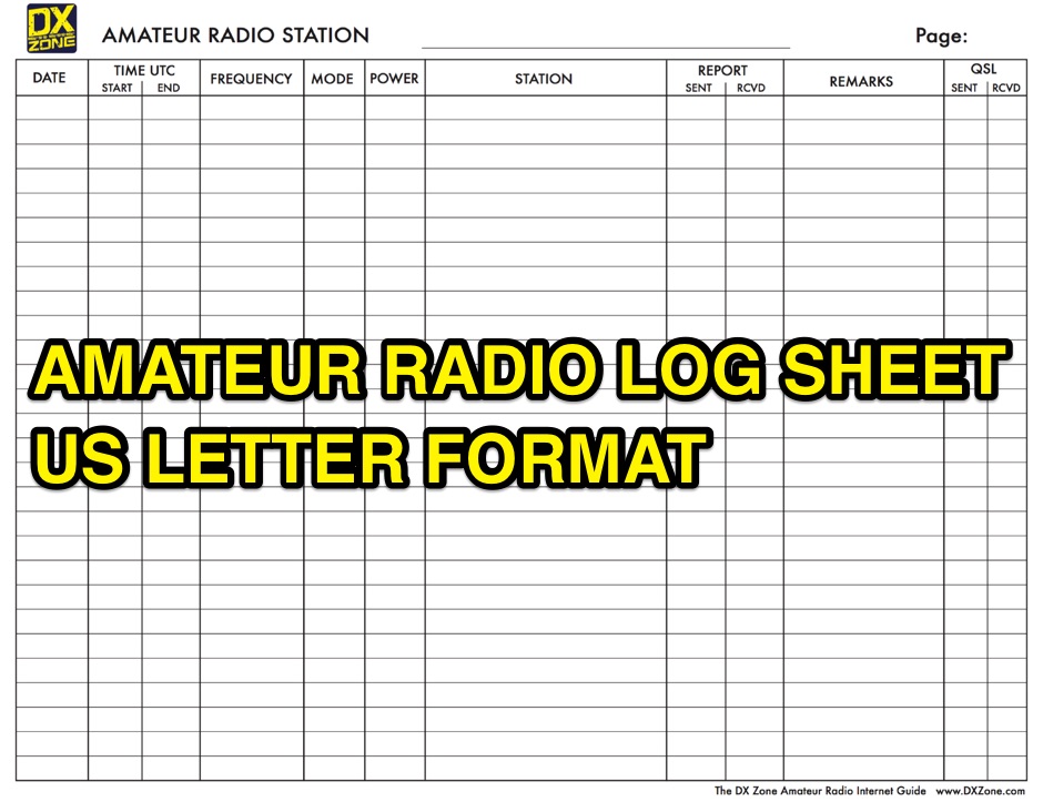 A free to download and print, amateur radio station log sheet in a paper US letter format
 -
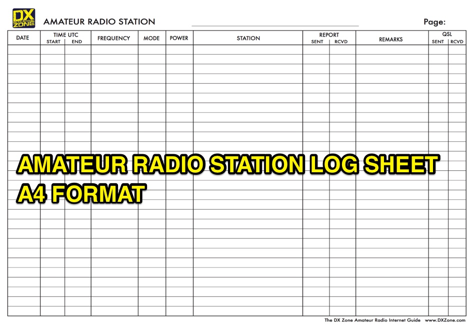 A free to download and print, log sheet in A4 paper format for amateur radio stations
 -
 An antenna does not have to be resonant to work, as the primary reason for resonance is to eliminate the need for an impedance-matching device. A non-resonant wire dipole fed with open-wire line and an antenna tuner can function as an effective multiband antenna. Two wires are essential for powering an antenna, ideally with a balanced configuration like a dipole fed by parallel-wire line, though coaxial cable can be used with a 1:1 balun to mitigate RF feedback on the shield. Antenna gain is achieved by shaping and aiming RF energy, concentrating it in a particular direction, as seen in beam antennas or shaped radiation patterns of wire antennas. The function of an antenna tuner is to match the transceiver's 50 Ohm output to the antenna system's impedance, which can vary widely. Wire antennas do not always require center feeding; end-fed long wires or off-center-fed dipoles (Windom antennas) can be used, often requiring a counterpoise or radial system. Dipole antennas do not need to be perfectly horizontal; their legs can be bent, inclined, or even vertical, affecting feed point impedance. Vertical antennas shorter than a half wavelength necessitate a ground system, typically comprising radial wires, with more radials generally leading to greater efficiency. A 1:1 SWR indicates an impedance match but does not guarantee a good antenna, as an inefficient antenna with a poor ground system can still show a perfect SWR while wasting RF as heat. Always using the best feed line affordable is crucial for minimizing loss and maximizing RF signal delivery to and from the antenna.
 -
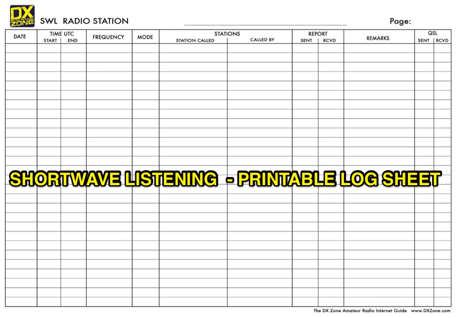 A free to download and print, paper log sheet for shortwave listerners in PDF format.
 -
 Managing extensive amateur radio contact logs efficiently requires specialized software that integrates various operational aspects. Aether provides a macOS-native logging solution, designed from the ground up using Apple's Cocoa, to streamline QSO entry, organization, and retrieval for Mac users. It supports modern macOS technologies and offers an intuitive interface, aligning with the user experience expected on Apple platforms. The application includes features such as automatic dupe checking, which quickly identifies previous contacts with a station, and awards tracking, indicating if a new contact is needed for specific operating awards. Aether also integrates rig control via RS-232, automatically populating frequency, mode, and power data from supported Elecraft, Icom, Kenwood, Yaesu, and some TEN-TEC transceivers. This automation reduces manual entry errors and speeds up the logging process. Furthermore, Aether offers comprehensive QSL management, including synchronization with eQSL.cc and Logbook of The World, and the ability to print QSO detail and address labels for paper QSLs. It also incorporates automatic callbook lookup from sources like QRZ.com and HamQTH.com, and calculates distance and beam heading, with Google Maps integration for visualizing contact locations. Full ADIF and Cabrillo import/export capabilities ensure compatibility with other logging software and contest submission platforms.
 -
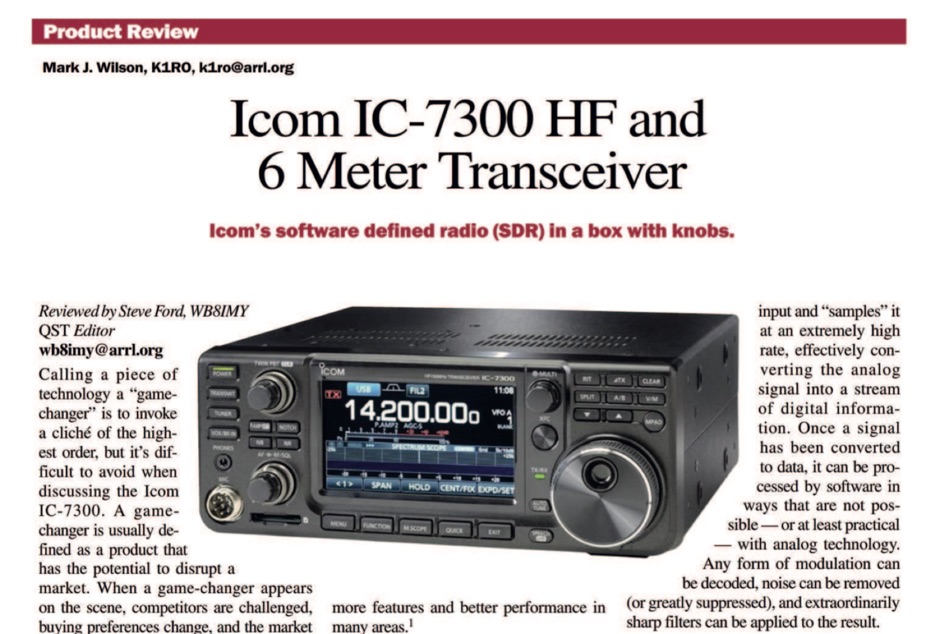 The ICOM IC-7300 is a cutting-edge HF transceiver that has garnered significant attention since its release. This review, published by ARRL in QST, provides an in-depth analysis of its features, performance, and usability. The IC-7300 is known for its direct sampling technology, which enhances its sensitivity and selectivity, making it a favorite among amateur radio operators. The review covers various aspects, including the user interface, audio quality, and overall operational capabilities, providing valuable insights for both new and experienced hams. In addition to its technical specifications, the review discusses the IC-7300's performance in real-world scenarios, such as DXing and contesting. It highlights the transceiver's ability to handle weak signals and its versatility across different modes. The review serves as a helpful guide for those considering the IC-7300 for their station, offering a balanced perspective on its strengths and potential drawbacks. Overall, this review is an essential resource for anyone interested in the ICOM IC-7300 and its place in the amateur radio landscape.
 -
 Constructing a portable, high-gain antenna for _AO-40_ satellite operations presents unique challenges, particularly regarding mechanical stability and parabolic accuracy. This resource details the build of a 1.2-meter "brolly dish" antenna, utilizing a non-conducting fiberglass umbrella frame as its foundation. The project outlines a method for achieving a parabolic shape using stressed aluminum fly screen mesh, guided by practical geometry and a temporary dowel template. Key steps include selecting an appropriate umbrella with a suitable f/D ratio (ideally >0.25), removing the original fabric, and precisely cutting and attaching eight segments of fly screen to the struts to form the reflective surface. The construction process, which took approximately five hours for the author, _G6LVB_, resulted in a dish with an f/D of 0.27 (depth=270mm, diameter=1160mm, f=310mm). The article also describes a modification to a _TransSystem AIDC_ feed, incorporating a PCB reflector behind the dipole for easier mounting. Performance tests at a squint angle of 15 deg and a range of 50,000km yielded a signal-to-noise ratio of 33dB on the S2 beacon and 23dB for SSB signals, indicating strong reception. The author notes that the modified umbrella may not close fully without risking surface disfigurement.
 -
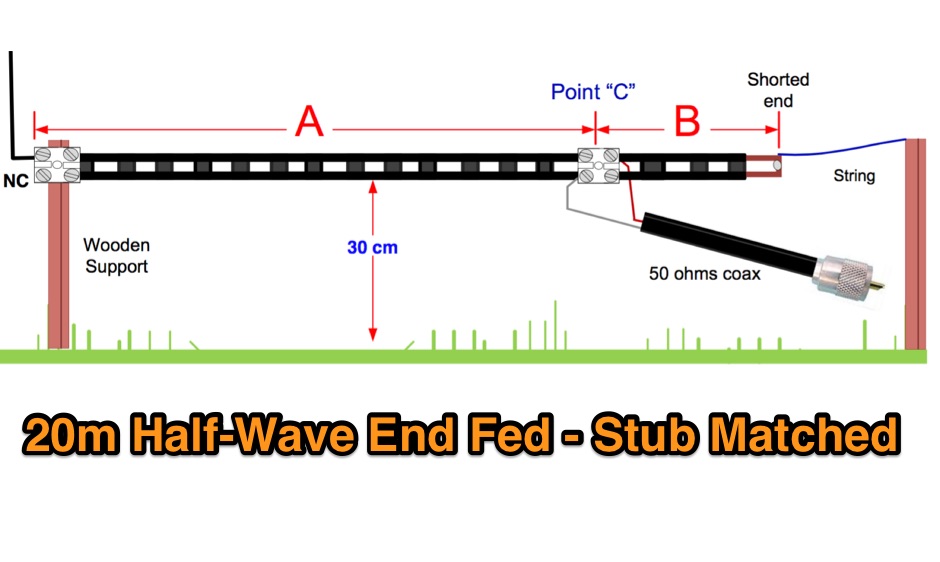 A Half wave antenna has a high impedance feed point. This can be matched using a 1/4 wave stub matching section and converts the 40m vertical into an L-shaped 20m J-Pole antenna. The 300 ohm feeder used for this purpose must be kept away from the ground.
 -
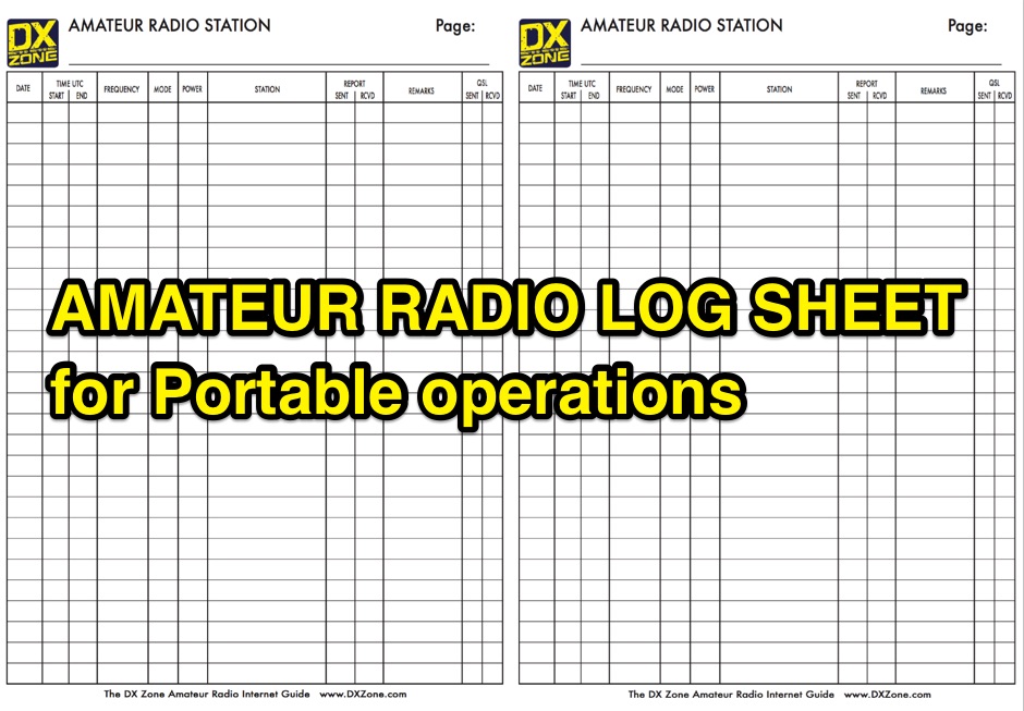 A free to download and print, paper log sheet useful for portable amateur radio operations, in a PDF file.
 -
 The SCOTIA Bandhopper, a multi-band mobile vertical antenna, offers a unique sliding coil design for rapid band changes across 10m to 80m. Drawing inspiration from the classic Webster _Bandspanner_, this design improves efficiency through near-center loading, theoretically achieving up to **2.25 times** greater radiation resistance than base-loaded counterparts. The antenna, extending to approximately 10 feet on 80m, utilizes a 5-foot fiberglass tube with an internal loading coil and a 57-inch tapered steel whip, allowing continuous tuning across bands without changing coils or whip sections. Field results from GM3VLB and the SCOTIA team, based on over 40 years of /M and /P operations, indicate the Bandhopper significantly outperforms shorter mobile whips. Its slim profile minimizes drag, making it suitable for sustained motorway speeds. The design incorporates a novel "fixed spring contact" arrangement for the variable inductance loading coil, with two sets of contacts for 10/12m and 15-80m. Construction details are provided, including materials like boundary marker poles and specific wire gauges, with an estimated build cost of **£20** or less, depending on junk box availability.
 -
 The AE6AC 17-meter Moxon antenna project details the construction of a wire beam using readily available materials. This design utilizes four 16-foot fiberglass crappie poles for support, joined at the center with 3/4-inch Schedule 40 PVC pipe and "T" slip fittings. Wire segment lengths for 18.135 MHz were calculated using _Moxgen_ software by AC6LA, with specific dimensions provided in feet and inches for precise cutting. Key construction decisions include joining the crappie pole bases into a central hub and attaching the 16-gauge silver-plated copper wire to the pole ends. Dacron cord with a fisherman's knot secures the wire to the pole tips, while small wire loops at the corners maintain antenna shape. Plexiglas pieces serve as insulators for sections "A" and "C." The finished antenna, weighing less than 10 pounds, mounts on a fiberglass windsurfer mast and incorporates a 1:1 current mode ferrite bead balun. Performance measurements with an _MFJ-259B_ show an SWR better than 1.5:1 across the 17m band, with good front-to-back ratio and reported signal strength improvements of 2-4 S-units over vertical dipoles. Initial contacts included VK2AXB, ZF6GS, and KL1M.
 -
 Ten essential tips and truisms for understanding HF antenna: Non-resonant wire dipole antennas fed with open-wire line and an antenna tuner can function effectively as multiband antennas, as detailed in "The Classic Multiband Dipole Antenna" by WB8IMY in March 2004 QST. Coaxial cable, unlike balanced parallel-wire feed lines, can cause RF to travel on the outer shield braid, leading to RF feedback to the station; a 1:1 balun at the dipole center can mitigate this by isolating the unbalanced coaxial feed line. Antenna gain is achieved by shaping and directing RF energy, with beam antennas concentrating power in a specific direction, and wire antennas also exhibiting shaped radiation patterns. An antenna tuner's primary role is to match the transceiver's 50-ohm output to the antenna system's impedance, allowing modern transceivers to deliver full power. Wire antennas do not always require center feeding; end-fed long wires or off-center-fed dipoles (like the Windom) can be used, though they often necessitate an antenna tuner and a counterpoise or radial network. Dipole antennas do not need to be perfectly horizontal; their legs can be bent or inclined, which affects feed point impedance and may require SWR experimentation with coaxial feed. Vertical antennas shorter than a half wavelength require an efficient ground system, typically comprising elevated or buried radial wires, with more radials generally leading to better efficiency. A 1:1 SWR indicates an impedance match but does not guarantee antenna efficiency; an inefficient vertical antenna with a poor ground system can show a low SWR while wasting most RF as heat. Investing in high-quality, low-loss feed line, especially coaxial cable, is crucial for maximizing RF signal transfer and overall antenna system performance.
 -
 An information paper by the International Amateur Radio Union, History of 40m allocation, propagation properties of 7 Mhz band
 -
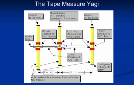 A presentation of the Yagi Antennas, and other interesting tid-bits by Brian Mileshosky. The document provides an in-depth exploration of the Yagi-Uda antenna, detailing its historical development, design principles, and performance characteristics. Originally described in the 1920s, the Yagi antenna features a driven element and parasitic elements, including reflectors and directors, which collectively determine its behavior. The document highlights how element lengths, diameters, and spacing influence gain, impedance, and directivity. It also discusses the antenna's reciprocal nature and presents data on typical gain values for various element configurations. Additionally, the text covers practical considerations, such as the construction of a "Tape Measure Yagi" for amateur use, and touches on related antenna types like dipoles and their application in Near Vertical Incident Skywave (NVIS) communication.
 -
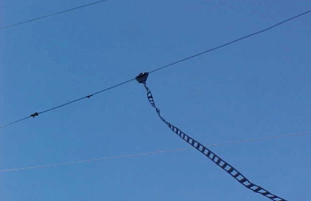 Complete collection of the four main parts of this excellet research on modelling and designing half wave dipole antennas for 40 meters band, covering all aspects beginning from full wave length antennas, to shortened, loaded and reshaped dipoles
 -
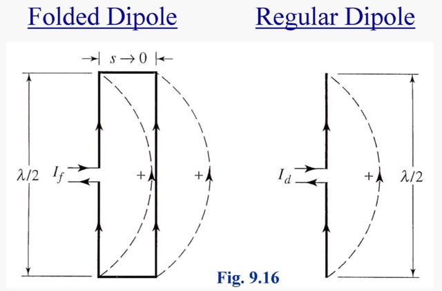 A folded dipole is an antenna, with two conductors connected on both sides, and folded to form a cylindrical closed shape, to which feed is given at the center.
 -
 This paper discusses the sources of feed line currents and the methods used to control them.
 -
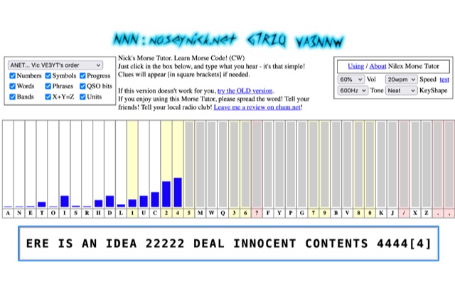 The **Nilex Morse Tutor** is an HTML5 web application designed to teach Morse code reception, adapting to user proficiency by adding new characters as readiness is detected. It prioritizes practice on less familiar letters, numbers, symbols, words, and phrases, while minimizing repetition of already mastered elements. The program offers multiple learning orders, including "Q7ZG..." (Ward/Jim's), "KMRS..." (PU5EPX/Koch), "KMUR..." (lcwo.net), "AENT..." (CWops CW Academy), "TEAN..." (Stephen C Phillips), "ANET..." (Vic VE3YT), and "ETI5..." (Ham Whisperer), alongside an alphabetical option. Users can customize the learning experience by enabling or disabling automatic progression, and selecting specific content categories such as numbers, symbols, words, phrases, QSO bits, Ham Radio Bands, X+Y=Z math, and units. Audio settings are adjustable for volume, speed (WPM), tone frequency, and keyshape/keying envelope, allowing for a personalized auditory environment. The interface provides visual feedback with blue bars indicating practice emphasis and gray bars for reserved characters, with clickable bars for manual character selection. Developed by "Nosey" Nick Waterman, VA3NNW, this tutor is based on earlier versions by Jim Wilson and a 1977 QST article. A significant October 2019 rewrite incorporated a new WebAudio sound library by AwesomeAidenW, improving offline functionality and mobile support. The content library was expanded to include 3000 top Google words, 2284+ General Service List words, ISO country codes, capital cities, US states, Canadian provinces, UK counties, common names, periodic table elements, quotes, Q-codes, electronic components, ham abbreviations, and example call signs. The software is distributed under the GNU GPL V2 license.
 -
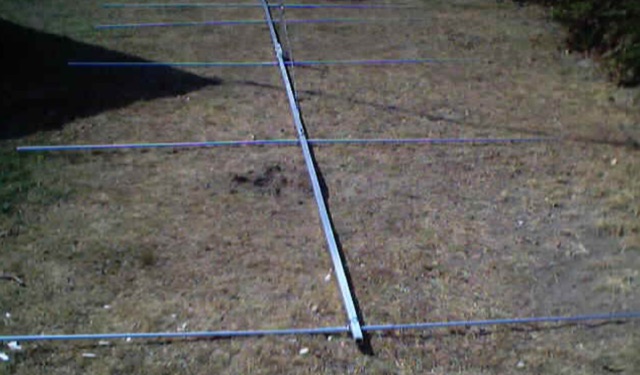 This is a design based on the QuickYagi 4 software by WA7RAI with some changes for practical reasons. The beam uses 6.5 metres of standard 25mm square boom, 12mm diameter elements without tapers. The actual boom length used is 6.3 metres and all parts are readily available.
 -
 This page provides updated data and statistics about United States amateur radio operators, including historical totals, demographics, and geographic distributions. It also explains the Amateur Radio Service, highlighting its role in promoting wireless communication and technological advancements. The page is a valuable resource for hams interested in understanding the current landscape of amateur radio in the United States.
 -
 An information paper by the International Amateur Radio Union. The amateur service seeks the return to an exclusive, worldwide allocation of no less than 300 kHz in the vicinity of 7 MHz.
 -
 Analyzes the operational dynamics of the _IARU R1 VHF contest_, the world's largest 2-meter contest, focusing on factors enabling top performers to maintain consistent results amidst declining overall activity. The resource investigates the physical constraints that limit higher point totals, examining how technical capabilities, increased interference, and evolving station setups contribute to contest outcomes. It provides insights into the strategic and technical aspects of achieving high scores, such as the **1,000,000+ point** totals observed from leading stations. Compares the performance of various stations over time, highlighting the sustained success of top contenders and speculating on future trends in VHF contesting. The analysis delves into specific operational strategies and equipment choices that differentiate high-scoring stations, offering a detailed look at the competitive landscape. It also considers the impact of propagation conditions and operator skill on final scores, providing a comprehensive overview of the contest's intricate mechanics and the pursuit of maximum QSO points.
 -
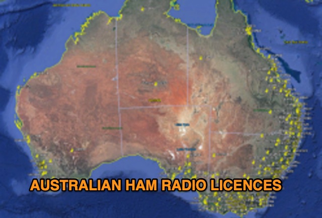 Discover a comprehensive solution for mapping Australian ham radio entities using data from the ACMA Public Register. This tool, developed in Delphi 7, generates KML files for Google Earth, showcasing repeaters, beacons, and operators across different prefixes. While respecting privacy regulations, the files provide valuable insights into the amateur radio landscape.
 -
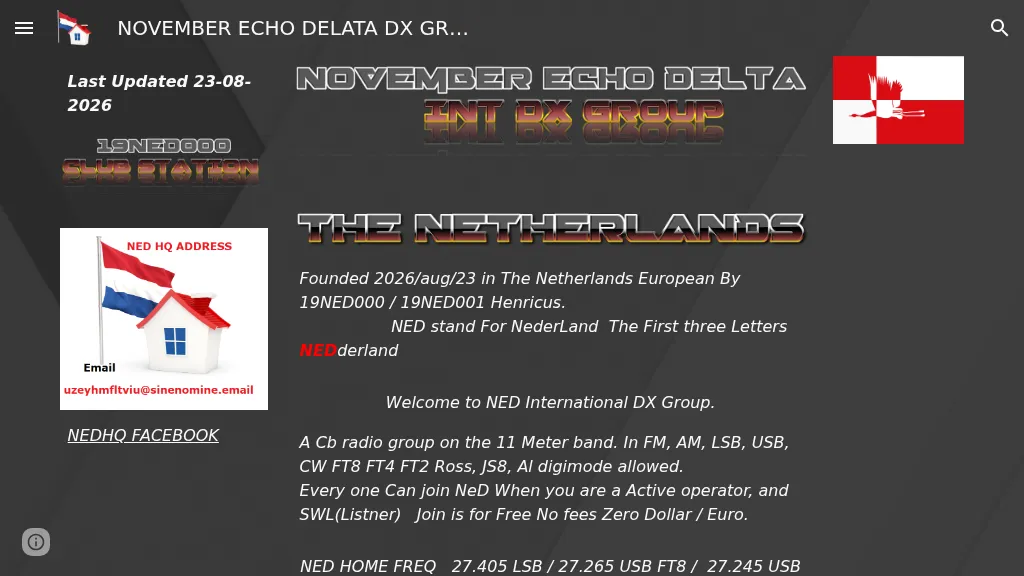 Presents the NED International DX Group, a **CB radio** organization established in the Netherlands on August 23, 2026, by 19NED000 and 19NED001 Henricus. The group primarily operates on the **11-meter band**, utilizing various modes including FM, AM, LSB, USB, CW, FT8, FT4, FT2 Ross, and JS8, with all digital modes permitted. Membership is free and open to active operators and SWLs. Key operating frequencies include 27.405 LSB, 27.265 USB for FT8, and 27.245 USB for JS8. The group also maintains activity on PMR Channel 10 at 446.11875 MHz FM. The organization is actively seeking volunteers for roles such as webmaster (proficient in PHP, MySQL, and security), digital eQSL and paper QSL card management, logo and banner design, and country/province directors.