Search results
Query: mg antenna
Links: 52 | Categories: 0
-
 The QM7 antenna is a simple 7 elements Yagi with 3.7 m boom length for the lower 144 MHz SSB/MGM band, in PDF Format
 -
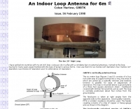 Indoor loop antenna for six meters band, project by Colen Harlow, G8BTK
 -
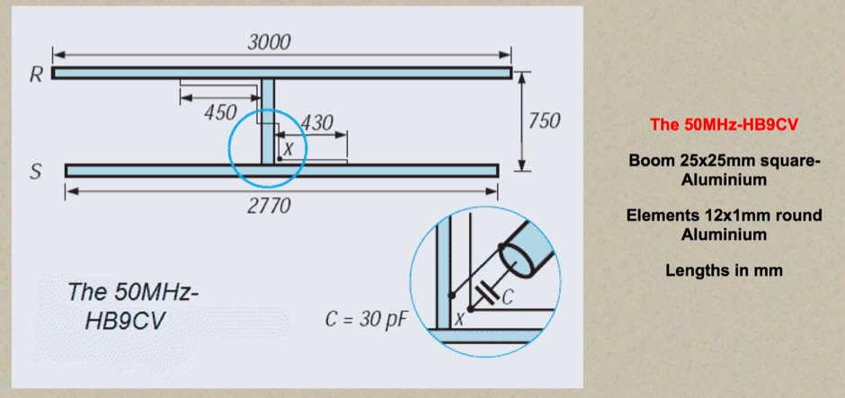 The HB9CV-Beam is a 2-Element-Yagi with two driven elements and was introduced by Rudolf Baumgartner, HB9CV in the 1950ies. This beam antenna is a coax-feeded version of the ZL-Special construction by DK7ZB for 2m, 6m and 10m
 -
 Complete plans and drawings to build a small 3 elements Yagi antenna for six meter band by Ken Willis
 -

-
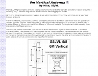 G3JVL Six meters ground plane vertical is a compact antenna that is ideal for portable operations on 50 Mhz
 -
 HF multiband mini delta compact and easy assembling antenna that cover from 20 to 10 meters by GM3VLB
 -
 This drawing shows a simple 10 meter wire J-pole antenna designed for 28.4 MHz. It is a vertical, end-fed Zepp-style antenna made from common materials and intended for easy home construction. The main radiating element is a straight length of stranded copper wire, either 14 or 18 gauge, cut to about 16.5 feet. At the top, the wire is supported by an insulator, allowing the antenna to be hoisted vertically. The matching section is made from 450-ohm ladder line, approximately 7 feet 9.5 inches long, and shorted at the bottom. This matching stub transforms the impedance so the antenna can be fed with coaxial cable. The feed point is tapped about 6 inches above the bottom of the stub, with the shield and center conductor connected at the proper points. A choke balun is formed with five turns of RG-58 coax in a 4-inch diameter loop to help reduce unwanted RF on the feed line. The drawing notes that this antenna has about 0 dBd gain, similar to a dipole, but offers an omnidirectional pattern and low-angle radiation when installed high. Its main advantage is practical performance, simple construction, and effective coverage for 10 meter operation.
 -
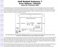
 The Bruce array is a simple, often-forgotten wire antenna array that is advantageous for 80 and 160 meters, where typical gain antennas are very large. This bi-directional broadside vertical array is only 1\4 lambda high and does not require a ground system. It offers substantially greater SWR bandwidth than the half-square or bobtail curtain. A 4-element Bruce array used by N6LF showed a gain of about 4.6 dB compared to a 1\4 lambda vertical with 8 elevated radials, with a 2:1 SWR bandwidth greater than 400 kHz. The antenna is simple and its dimensions are flexible.
 -
 HF Ham Radio mobile operation antennas manufacturer, W6HIQ, HA5CMG, VE7BOC, HF mobile antennas, screwdriver antenna, coils and filters.
 -
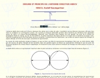 Basics and principles of the HB9CV antenna by Rudolf Baumgartner. This antenna join electric advantages of the two elements direct feeded aerials with the mechanical advantages of the Yagi antennas, in French.
 -
 The QM7 antenna is a simple 7 elements Yagi with 3.70 m boom length for the lower 144 MHz SSB/MGM band, used it mainly for Sporadic-E and MS contacts. It exhibits a forward gain of 11.35 dBd; i.e. 13.5 dB forward gain over the isotropic radiator, while the F/R is about 12.5 dB
 -
-
-
 A 40-meter reversible _Moxon rectangle_ antenna project details its construction and performance, featuring 51-foot long sides and 7.7-foot turned-in sections. The design incorporates a 16.5-foot boom, with elements spaced 1.1 feet apart, constructed from #14 covered wire. It utilizes two double-pole relays for switching between NE and SW directions, achieving F/B ratios up to 40 dB on CW and 30 dB on SSB, with distinct reflector stub settings for each mode. This antenna replaced a full-size 2-element Yagi, demonstrating comparable forward gain while offering superior F/B ratios and directional flexibility. _EZNEC_ modeling indicates only 0.2 dB less forward gain than the Yagi. The system uses no baluns, relying on half-wave feedlines and switched stubs for impedance matching. The antenna is tree-supported at 45 feet, with its effective radiation height modeled at 80 feet due to local terrain, enhancing its performance over a nearby lake.
 -
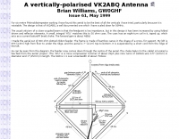
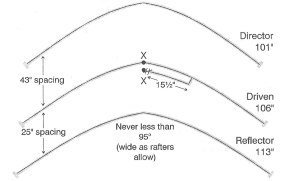 An option for restricted and limited space, to operate the six meters band with an indoor three elements yagi antenna by Brian Williams
 -
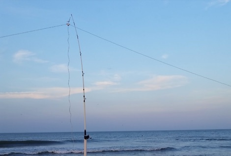
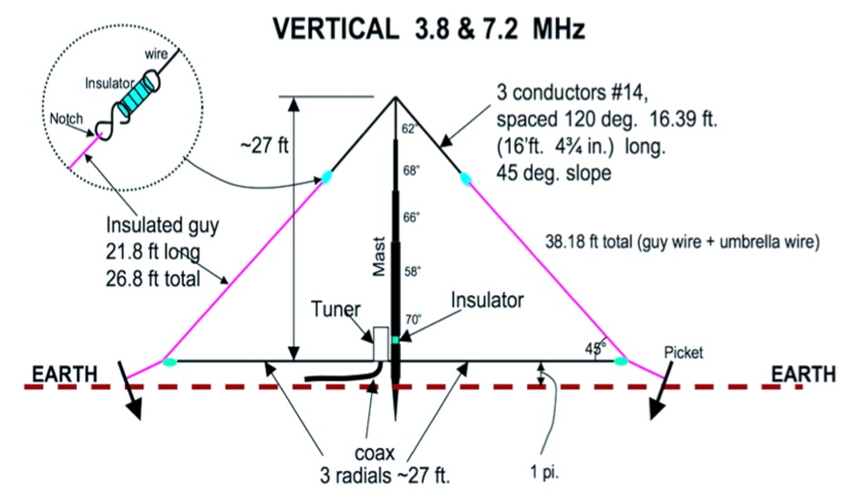 Portable Vertical Antenna for 75m and 40m featuring Low radiation angle for DX, easy to install and to match 50 ohms
 -
-
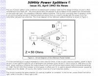 Splitting an antenna between two receivers or in use as the phasing harness in stacked antennas where there is a need to equally split the power from the transmitter between two antennas
 -

-
 Presented here is a high-performance, circularly polarized omni-directional antenna that is easy to build, easy to tune, inexpensive, and will work all the mode J Low Earth Orbit (LEO) satellites
 -
 A 40 80 dipole antenna design by WA6ESC PDF File
 -
 A home made vertical polarized moxon antenna for 144 MHz, includes dimensions, antenna pattern, SWR and antenna gain plots by WB5CXC
 -
 Gap Titan DX Antenna manual. This is an enhanced version of the common Gap Titan DX Manual document you can download from other sites. This manual is in PDF Format.
 -
 Demonstrates the design and construction of a compact, portable multi-band mini-delta loop antenna, specifically optimized for /P (portable) operations from remote locations like Scottish islands. The resource covers the theoretical underpinnings of half-wave loops, contrasting closed and open configurations, and then details the application of a folded dipole principle to achieve a 50-ohm match for direct coax feed. It presents empirical formulas for calculating element lengths, considering the velocity factor of common wire types, and provides a detailed example for a 20m (14.175 MHz) version. The article includes a comprehensive table of dimensions and allowances for a five-band (20m, 17m, 15m, 12m, 10m) mini-delta beam, along with construction hints for the central support and balun. It specifies a 1:1 trifilar balun wound on a ferrite rod and describes the antenna adjustment process using an _MFJ-259B Antenna Analyser_. Initial test results indicate an SWR of 1:1 at resonance and a bandwidth of approximately 240 kHz on 20m, even at a low height of five feet above ground. The distinctive utility lies in its focus on a practical, easily deployable beam antenna for portable DXing, offering a viable alternative to more complex or larger arrays.
 -
 50 MHz meteor scatter offers a unique opportunity for amateur radio operators to make long-distance QSOs, even when the band appears dead. Meteor scatter involves reflecting radio waves off the ionized trails left by meteors burning up in the upper atmosphere, typically around 105 km high. These trails can facilitate contacts over distances up to approximately 2,300 km. The technique is particularly effective during meteor showers, which increase the number of meteors and thus the chances of successful QSOs. However, random meteors can also be used to achieve contacts, especially on the 50 MHz band, where the longer reflection time compared to 144 MHz makes it easier to work meteor scatter. Operators should be prepared to make QSOs in short bursts, often lasting only a few seconds. The IARU Region 1 meteor scatter procedure recommends using 2.5-minute periods for telegraphy and 1-minute periods for SSB, though shorter periods can be arranged. For 50 MHz SSB, 15-second timing is often used to maximize the chances of completing a contact. The procedure involves specific timing for transmissions based on direction and requires both operators to confirm receipt of callsigns and reports to complete a QSO. Understanding the geometry of meteor scatter, including the optimal radiation angles and the concept of 'hot spots,' is crucial. These hot spots are areas where reflections are most likely to occur, influenced by the Earth's rotation and the path of the meteors. Proper antenna setup, including elevation control and beam direction, can significantly enhance the chances of successful meteor scatter QSOs.
 -
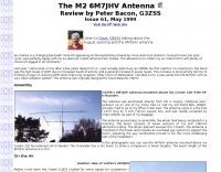
 In the long history of beam aerials there has persistently existed the claim that certain types of aerials perform better than yagis.
 -
-
 A 21 MHz Four Square Beam Antenna This popular antenna for the lower bands, can also work well on 15 meters, QST Article
 -

-
 A multi-band portable vertical antenna can be built with relatively ordinary components obtained from the local hardware store, including replaceable loading coils
 -
 The _Italian VHF Beacons_ resource provides a detailed listing of active and QRT amateur radio beacons operating across VHF, UHF, and SHF bands within Italy. Each entry specifies the beacon's callsign (e.g., IQ1SP/B), operating frequency (e.g., 144.411 MHz), QTH locator (e.g., JN44VC), effective radiated power (ERP) in watts, and antenna configuration (e.g., Big Wheel, 4x Dipole, Yagi). This data is crucial for radio amateurs involved in propagation studies, equipment testing, and long-distance (DX) communication on these higher frequency bands, offering fixed signal sources for monitoring. This compilation, last updated in October 2005, serves as a historical snapshot of Italian beacon activity. For instance, it lists several 144 MHz beacons with ERPs ranging from **0.1W** to **10W**, and higher frequency beacons such as I8EMG/B on 1296.880 MHz and I3EME/B on 24192.132 MHz. The inclusion of QRT (Quiet Radio Teletype) status for many entries indicates the dynamic nature of beacon operations over time. Users can utilize this information to identify potential signal sources for band openings or to calibrate their receiving equipment against known transmissions.
 -
 Summary of discussion on stacking antennas on six meter band
 -
 Decoding NOAA APT weather satellite images is achieved with a homebrew receiver and a Turnstile Cross Dipole antenna, feeding data to a Pentium-3 500MHz PC running Windows XP and the WXTOIMG program. This setup, operated by VU2IIA in Mumbai, India, focuses on capturing and processing signals from NOAA satellites to generate visual weather data. The blog documents the technical aspects of constructing the receiving station, including antenna design and receiver integration. It provides insights into the practical challenges and successes of amateur satellite reception, specifically for Automatic Picture Transmission (APT) signals. Operational details cover the software configuration and image processing workflow necessary to transform raw satellite data into usable weather imagery. The content serves as a practical guide for radio amateurs interested in satellite meteorology.
 -
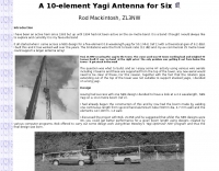
 Article describing how to homebrew a yagi antenna for 50 MHz, includes plans for a four and five elements yagi beam and details how how match impedence with a gamma match
 -
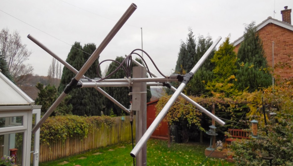 An homebrew Lindenblad antenna designed specifically for LEOs reception.
 -
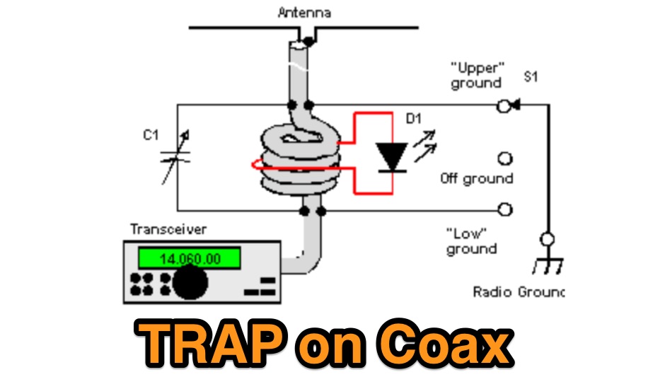 A trap on the coaxial cable, also known as choke, helps to eliminate the sneaking of the reflected RF- energy to the shack. The trap can be made from the coaxial cable that feeds the antenna
 -
 The resource details the construction of a multiband trap-style Inverted-V antenna designed for operation on 3.5 MHz, 7 MHz, 14 MHz, 21 MHz, and 28 MHz. It presents specific winding data for the traps, including the number of turns, wire gauge, and coil former dimensions, crucial for achieving resonance on the target bands. The document provides a parts list and a diagram illustrating the antenna's physical layout and trap placement. It outlines the process for building the traps using PVC pipe formers and specifies the required capacitor values for each trap. The design emphasizes a practical approach to achieving multiband operation with a single feedline, a common goal for HF operators with limited space. The document includes a table with antenna segment lengths for each band, allowing for precise replication of the design. It also offers insights into tuning and adjustment, ensuring the antenna performs optimally across the designated amateur radio bands.
 -

-
 This article is about a simple vertical end-fed-half-wave wire antenna for 10 meters that can be used in case of restricted space.
 -
 Want to operate on 40 meters but only have a space a little over 16X16 ? Try this antenna.
 -
 KB9AMG's Top WSPR Spots presents a focused online tool for monitoring **2-way WSPR reports**, specifically detailing propagation data from February 2026 through March 2026. This resource aggregates _WSPRnet_ data, allowing radio amateurs to observe weak signal propagation conditions across various bands. The interface is straightforward, presenting callsigns, frequencies, signal-to-noise ratios, and distances for each reported contact, which is crucial for understanding current band openings and signal paths. The utility of this WSPR spotter lies in its ability to quickly visualize global propagation. Users can identify active stations and assess signal viability over long distances, with reports often showing contacts spanning thousands of kilometers. For instance, a typical WSPR report might indicate a signal from Europe reaching North America with a _SNR_ of -25 dB, demonstrating effective low-power communication. This data is invaluable for planning DX operations or evaluating antenna performance under actual propagation conditions.
 -
 This article is about a 4 element yagi VHF antenna designed to be easy to be assembled and suited for portable operations
 -
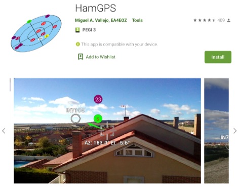 Display your current Maidenhead locator with 10 digit precision. It also computes bearing and distance to a set of target locations using locator or latitude / longitude. Useful to align antennas in VHF / UHF / microwave DX activities. No network or fancy maps usage, so it can be used even in remote locations.
 -
 A portable wire antenna for the HF bands, made with a common speaker wire. In its natural form, the speaker wire acts as parallel feed line coming up to the bottom of the PVC feed point. From there, it's split into two wires, one heading out each side of the PVC tee.
 -
 Low-frequency (LF) radio time signals, operating primarily in the 40–80 kHz range, are broadcast by national physics laboratories for precise clock synchronization. Transmitters like **JJY** (40 kHz, 50 kW; 60 kHz, 50 kW), RTZ (50 kHz, 10 kW ERP), MSF (60 kHz, 15 kW ERP), WWVB (60 kHz, 50 kW ERP), RBU (66.66 kHz, 10 kW), and DCF77 (77.5 kHz, 50 kW) cover vast geographic areas, often several hundred to thousands of kilometers. LF signals offer distinct propagation advantages over higher-band transmissions such as GPS. Their long wavelengths (3–6 km) enable effective diffraction around obstacles like mountains and buildings. The ionosphere and ground act as a waveguide, eliminating the need for line-of-sight and allowing a single powerful station to cover extensive regions. Ground wave propagation minimizes ionospheric variability effects on transmission delay, and signals penetrate most building walls effectively. Robust and low-cost receivers, often priced at 20–30 USD/EUR, are widely used in radio clocks. These receivers typically comprise a tuned ferrite core antenna, a receiver IC (e.g., Atmel T4227, U4223B, MAS1016) for amplification and AM detection, and a microcontroller for decoding the time signal and phase-locking a local clock. Specific components for DCF77, MSF, and WWVB are readily available from vendors like HKW Elektronik and Ultralink.
 -
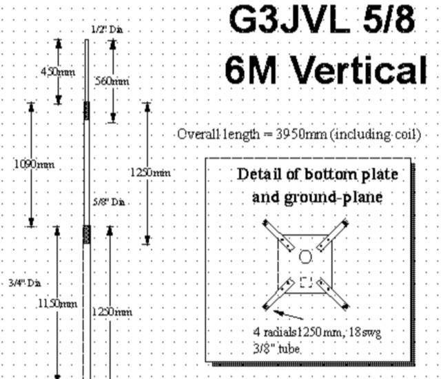 The G3JVL 6M ground plane vertical is a compact antenna that is ideal for portable operations. It packs away into a small bag only 1.3 metres long which is an ideal size for hand-baggage on aircraft.
 -
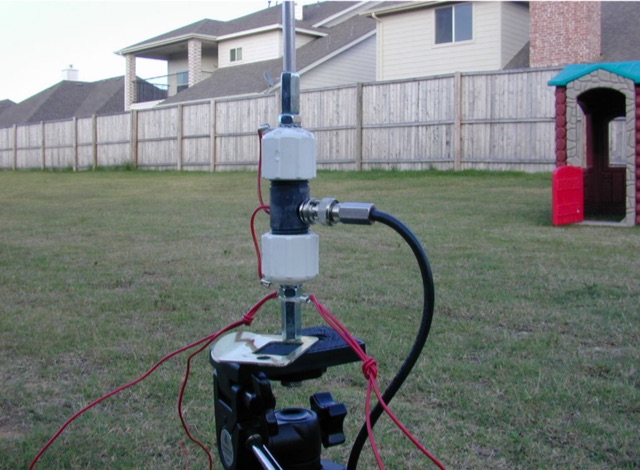
 This article shares the author's experience with building antennas. After putting a large magnetic loop project on hold, they decided to try a base-loaded vertical antenna. The author explains how they chose to design a new antenna from scratch, aiming for a frequency of 7 MHz. They describe the calculations needed to find the right coil inductance and how they used 3D-printed parts for the construction. The article wraps up with results from their initial tests, showing good communication on different bands and highlighting the success of their design.
 -
 Amateur Radio goodies for not only the Shack, but also a range of outdoor/portable kit. Ferrite toroids, RTL SDR, Un-uns and Baluns for antennas and RF Filters. Based in the UK.
 -
 This blog post documents the author's journey building an APRS micromodem for amateur radio applications. Using an open-source design by LY2EN, the author assembled a cost-effective Terminal Node Controller (TNC) with SMD components, an Arduino Nano, and a JDY-31 Bluetooth module. The construction process included PCB fabrication, careful component soldering, microcontroller programming, and Bluetooth configuration. A custom 3D-printed case protected the completed device. Field testing in Romania showed the device functioned with a Baofeng UV-5R radio, though antenna limitations affected performance. The entire project demonstrates an affordable DIY alternative to commercial APRS trackers.