Search results
Query: range calc
Links: 26 | Categories: 0
-
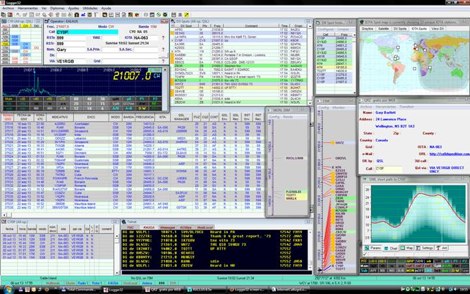 Logger32 is a well-established amateur radio logging program designed primarily for DXers who require a flexible and data-driven logging environment. The software maintains a comprehensive logbook database capable of handling large volumes of QSOs while offering detailed tracking of DXCC entities, awards, and band/mode statistics. One of the core strengths of Logger32 is its DX cluster integration. The program connects to telnet DX clusters and displays spots in real time, with filtering options by band, mode, country, or callsign. The cluster window can automatically highlight needed DXCC entities, band-fills, or new modes based on the operator’s log. Logger32 also provides rig control through CAT interfaces, supporting a wide range of transceivers via serial or USB connections. When properly configured, frequency and mode are automatically captured in the log entry window. The software supports digital mode integration through external applications and can exchange information using standard interfaces. Another important feature is its award tracking system, including DXCC, WAS, IOTA and other common amateur radio awards. The program calculates worked, confirmed, and needed entities with detailed reports. Logger32 supports ADIF import and export, allowing interoperability with other logging systems. It also includes QSL management, with tracking for bureau, direct, and electronic confirmations such as LoTW or eQSL when configured. Overall, Logger32 remains a technically capable logging solution focused on DX tracking, cluster awareness, and detailed statistical analysis of operating activity.
 -
 Constructing a 2.4 GHz high-gain _cantenna_ for wireless networks is detailed, providing a practical approach to extending WiFi range. The author, WB8ERJ, shares insights into building these devices, noting their application in amateur radio for projects like Hinternet or HSMM (High-Speed Multimedia) networks. The article outlines the necessary components and steps, emphasizing the DIY aspect for hams interested in digital modes and local area networking. The resource explains how to determine the correct probe placement within the can, a critical dimension for optimal performance at 2.4 GHz. It references specific measurements, such as the 1.25-inch distance from the can's bottom, derived from calculations for the 2.4 GHz band. This precision ensures the antenna functions effectively for its intended purpose of signal amplification. Readers gain actionable knowledge for fabricating a functional antenna from common materials, suitable for experimentation or practical deployment in a ham shack or field environment. The focus remains on the hands-on construction and the measurable results of improved signal strength.
 -
 The project details a DIY SWR/Wattmeter designed around an _Arduino Uno_ shield, providing capabilities to measure RF power from 2 to **200 watts** and Standing Wave Ratio (SWR) for HF amateur radio bands. This construction features a compact design, integrating the measurement circuitry directly onto a custom PCB that interfaces with the Arduino Uno microcontroller. Key components include a directional coupler for sensing forward and reflected power, precision rectifiers, and analog-to-digital conversion for processing RF signals. The Arduino firmware handles calibration, calculations, and displays the results on an integrated LCD, offering real-time feedback on antenna system performance. The design prioritizes simplicity for homebrewers. Performance specifications indicate accurate readings within the **2-200W** power range, suitable for typical QRP to medium-power HF operations. The project provides schematics and a basic overview of the software logic.
 -
 Kioan's calculator for building a Cantenna , directional waveguide antenna for long-range Wi-Fi
 -
 Calculating and building an Eggbeater antenna. InstantTune and push-button Rx. Documentation available in french and english
 -
 Demonstrates a **DX cluster** web service providing real-time amateur radio spot reports, propagation information, and solar data. The platform integrates features such as a gray line map, **DXCC** tracking, and a personal logbook, allowing users to manage their confirmed entities and contacts. It supports various bands from 160m to 70cm, including specific filters for modes like FT8/FT4, and offers both web and Telnet access for spotting and monitoring. The service provides graphical representations of spot reports, detailing activity across different frequency bands and modes (CW, SSB, digital). Registered users gain access to advanced functionalities, including personalized filters and tools for calculating DXCC status. The platform also includes a classifieds section and options for mobile access, catering to a broad range of amateur radio operators interested in DXing and contesting.
 -
 PA3FWM's software defined radio (SDR) page documents his extensive hardware and software development efforts between 2004 and 2009. Initial experiments utilized a direct conversion receiver with 90-degree phase difference, feeding a PC soundcard at 48 kHz sample rate, covering 24 kHz of spectrum around a 7080.5 kHz local oscillator. This setup, similar to AC50G's QEX 2002 article, allowed for basic I/Q signal processing to distinguish signals above and below the LO frequency. Limitations included fixed crystal frequencies, 16-bit dynamic range, and narrow bandwidth. Subsequent hardware iterations aimed for enhanced performance, incorporating external 24-bit ADCs with 192 kHz sample rates, connected via 10 Mbit/s Ethernet. A **MC145170-based PLL** and programmable octave divider provided a 58 kHz to 30 MHz tuning range. The **Tayloe mixer** was employed, with differential outputs feeding a PCM1804 ADC. An ATmega32 microcontroller handled serial data conversion to Ethernet frames, though without CRC calculation due to processing constraints. Later designs integrated AD7760 2.5 Msamples/second ADCs and a Xilinx Spartan-3 FPGA, enabling direct reception of 0-1 MHz spectrum and eventually 2.5 MHz bandwidth across the shortwave spectrum. Software was refactored to use an initial 8192 non-windowed FFT for efficient high-bandwidth processing. The project culminated in a two-way QSO on 21 MHz using the developed hardware and software, demonstrating transmit capabilities with a D/A converter. The system exhibited a 2.5 MHz wide spectrum display and a zoomed 19 kHz display, capturing signals like ionospheric chirp sounders and RTTY contest activity. Challenges included noise leakage from digital circuitry and cooling for high-power dissipation components.
 -
 Demonstrates the construction and measurement of a single-turn HF receiving loop antenna, built from common materials like electrical conduit and lamp cord. The resource details the physical dimensions, including a 4-meter circumference, and calculates the theoretical inductance at approximately _6.4 uH_. It outlines a method for determining resonant frequencies across the 4-17 MHz range using a _C Jig_ and a _VR-500 receiver_, coupling the loop with a ferrite ring. The article also discusses the impact of receiver coupling on the loop's Q factor, noting a degradation in sharpness due to the transformer's reflected impedance. Analyzes the observed resonant frequency patterns, highlighting an unexpected rise in the loop's effective inductance at higher frequencies, particularly above 13 MHz. While some increase is attributed to distributed capacitance, the rate of rise suggests further investigation. The experimental setup provides practical insights into the challenges of maintaining high Q in simple receiving loops and offers a comparative reference for other homebrew antenna projects, such as those by _VK2TPM_.
 -
 HB9DNU Karlheinz's blog, hosted on Blogger, presents a collection of personal reflections and observations, predominantly in German. The content spans various non-amateur radio subjects, including Swiss political initiatives, economic discussions concerning banks like UBS, and social commentary. For instance, an entry from February 2008 details the Swiss vote on a combat jet noise initiative, highlighting the debate between tourism concerns and national security. Another post from October 2008 critiques the 500 billion Euro bailout package for banks, calculating its per-capita cost for German citizens and referencing earlier blog entries from March 2006 and June 2007 that discussed UBS salaries and Raiffeisenbank issues. These entries often reflect Karlheinz's personal perspective on current events. The blog also includes lighter, more personal notes, such as a February 2009 entry about a video produced by his grandson, and observations on local events like a bird exhibition in Contone or a scenic train ride through the Centovalli, demonstrating a broad range of interests beyond the ham radio hobby.
 -
 The Receiver Test Data resource is a detailed review database focusing on the performance metrics of various radio receivers. The methodology involves rigorous lab measurements, often adhering to standards such as the ARRL RMDR (Reciprocal Mixing Dynamic Range) and BDR (Blocking Dynamic Range). Specific test equipment and protocols are utilized to assess parameters like noise floor (dBm), AGC threshold (uV), and LO noise (dBc/Hz). For example, the _Icom IC-7300_ is evaluated with a noise floor of **-133 dBm** and an LO noise of **-141 dBc/Hz**, providing insights into its performance under different operational conditions. The resource includes a wide range of models, from the _Elecraft K3S_ to the _Yaesu FTdx-101D_, each tested for dynamic range, sensitivity, and selectivity. The data is sorted by key metrics such as third-order dynamic range and phase noise limitations, with RMDR values calculated by subtracting 27 dB from LO noise figures. This structured approach allows users to compare different receivers' capabilities, focusing on technical specifications and performance outcomes in various scenarios. DXZone Focus: Review Database | Lab Measurements | -133 dBm | ARRL RMDR
 -
 This simple antenna modelling windows software by F5IMV wil calculate a dipole,extended double Zepp,G5RV, ZS6BKW and many other wire antennas by F5IMV
 -
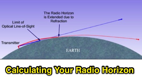 The range and coverage of your VHF transceiver will be limited to your radio horizon. How to calculate the visual horizon and how to determine the Radio Horizon
 -
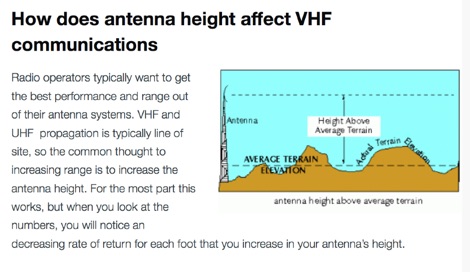 How to calculate range for a VHF antenna with a simple formula and how to increase VHF coverage.
 -
 137 kHz propagation analysis details ground wave and sky wave mechanisms, drawing heavily from **CCIR Rec. 368-6** for ground wave field strength predictions and **CCIR Rep. 265-7** for sky wave modeling. The resource presents field strength values for 1 W ERP at varying distances, considering ground conductivity and permittivity for ground wave, and ionospheric height (70km daytime, 90km nighttime) for sky wave. Key factors like ionospheric focusing (factor "D"), reflection coefficient ("RC"), and antenna ground pattern factors ("Ft", "Fr") are quantified for 137 kHz, enabling calculation of sky wave field strength. Practical coverage ranges are derived for 137 kHz, showing useful ground wave coverage up to 1600 km over seawater and 1100 km over average ground, assuming a -9 dBuV/m noise floor. Sky wave coverage extends beyond 2200 km during night-time and winter daytime, but is negligible during summer daytime at solar minimum. The document also compares ground wave and sky wave strengths, identifying crossover distances at 550 km (night-time), 750 km (winter daytime), and 1250 km (summer daytime), where interference fading can occur. Adjustments for solar maximum conditions are provided, indicating 2-11 dB higher sky wave values depending on distance and season.
 -
 When assembling a robust shack, the quality of interconnects often determines overall system integrity and signal fidelity. Neutrik, with over 50 years in the connectivity sector, specializes in professional-grade connectors that withstand rigorous use in entertainment and industrial applications. Their product range includes XLR, speakON, powerCON, and opticalCON series, which are frequently adapted by hams for critical station infrastructure, particularly in contesting or DXpedition environments where reliability is paramount. Amateur radio operators often repurpose these durable connectors for antenna switching matrices, audio interfaces for digital modes, or power distribution systems. The robust locking mechanisms and high-quality contact materials found in Neutrik products ensure stable connections, minimizing intermittent faults that can plague field operations or even fixed station setups. This attention to mechanical and electrical integrity aligns well with the demands of high-power RF environments and sensitive receive chains. While primarily serving the pro-audio and video markets, the engineering principles behind Neutrik's designs translate directly to the needs of radio amateurs seeking superior performance and longevity from their cabling and connection points. Their commitment to innovation, as highlighted by their 50-year journey, suggests a continuous evolution of products that could benefit future amateur radio applications.
 -
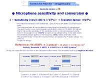 Mic online calculator , Microphone Dynamic Range Calculator, Microphone Sensitivity Calculator
 -
 Constructing a basic multimeter involves integrating a 0-1mA meter movement with various shunts and multipliers, selected via a switch, to create a versatile instrument capable of measuring DC volts, current, and resistance. The design outlines two main units: a primary unit handling six DC current ranges up to 1 amp and eight DC voltage ranges up to 1000 volts, alongside an internal battery for an ohms range up to 200,000 ohms. This approach allows for a practical, hands-on understanding of meter operation. An add-on unit further extends the multimeter's capabilities, incorporating a meter rectifier and switched series resistors to provide four AC voltage ranges up to 100 volts. Additional shunt and series resistors, designated Ra and Rb, are included to expand the instrument's range to 10A and 5kV, demonstrating how modular design can enhance functionality. When this add-on is in use, the main instrument is set to measure 1mA FSD, connecting via specific lugs. Component selection emphasizes precision, with 1% tolerance high stability resistors for series elements and Eureka resistance wire for shunts. The design specifies values calculated for a meter with 60 ohms internal resistance, noting that these would require modification for different meter characteristics. Experimental adjustment of shunt values is recommended to ensure accurate readings against a calibrated reference meter, reinforcing practical calibration techniques.
 -
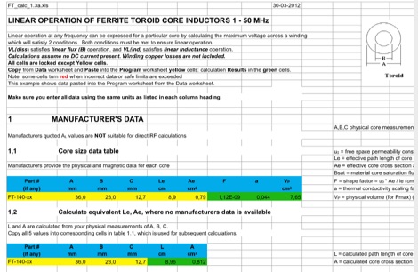 This EXCEL Program Worksheet calculates the safe operating conditons for a toroidal transformer operating between 1 and 50 MHz. Manufacturer data for complex permeability, magnetic dimensions, and saturation flux density must be available. Some core types which are commonly used in amateur transmission are included. The program produces limiting winding voltages for linear operation and temperature rise over the range of frequencies and power specified.
 -
 The Tri-pole antenna, a clever modification of a standard dipole, allows for dual-band operation by integrating a third element. This design effectively shortens the overall dipole length by 10 to 20 percent, simplifying antenna rotation and offering a compact footprint. KK4OBI's article delves into the operational principles, using a 6 and 10-meter Tri-pole as a primary example, and provides comprehensive instructions for constructing any Tri-pole antenna within the 6 to 15-meter range. Key to the Tri-pole's performance is its off-center feed, necessitating a common mode choke at the feed point for optimal tuning and reduced noise. The author outlines a methodical approach to determining element dimensions, starting with a vertical element frequency calculated as 0.47 times the sum of the desired upper and lower band frequencies. This calculation, along with K-values derived from trend lines, guides the initial lengths for the horizontal arms, demonstrating how a 10m-6m Tri-pole can achieve a total horizontal length 78% shorter than a conventional 10-meter dipole. Tuning and balancing are critical, with the article detailing adjustments to arm lengths and the vertical element to achieve balanced SWR values, as validated through 4NEC2 simulations. Radiation patterns are analyzed at various elevations, showing gains around 5.7 dBi and favorable take-off angles for DX contacts. Construction details specify aluminum tubing dimensions, U-bolts, and an SO-239 connector, emphasizing the importance of a ferrite-based choke for wideband operation.
 -
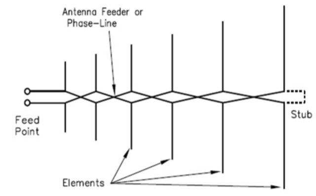 Description and online calculator for Log Periodic Dipole Arrays LPDA are directional antennas featuring a relatively constant characteristics across a wide frequency range.
 -
 Enables Android users to operate various _miniVNA_ antenna analyzers via Bluetooth, USB, or Wi-Fi, providing a portable solution for RF measurements. The application supports full control over data acquisition, offering features like custom frequency range selection from 1 KHz to the VNA's full range, and automatic screen adaptation for diverse Android device resolutions. It facilitates intuitive, wizard-based calibration for both reflection and transmission modes, saving calibration data for different VNA types (Standard, Pro, Pro with Extender) to avoid repeated procedures. The software displays critical parameters such as SWR, |Z|, Return Loss, Phase, Rs, and |Xs| on 2-axis graphs or Smith charts, with multi-touch gestures for zoom and frequency shift. It includes a frequency generator mode with independent channels and attenuator control for the miniVNA Pro, along with a sweeper function. The cable data mode automatically calculates phase and loss, measures cable length from less than 1 meter to hundreds of meters, and includes a table of common coax cable velocity factors. An experimental X-tal mode measures resonance frequency, Rs, and Q. Data export options include CSV, ZPLOT, and S1P formats, with CSV import capability. The application also features an SM6ENG Audio mode for SWR tuning without visual reference and provides a miniVNA battery voltage indicator. It supports a wide frequency range, with the miniVNA Extender extending coverage up to **1500 MHz**. The application is compatible with Android version 2.2 and later, tested on devices like the _Galaxy TAB 7.7 P6800_.
 -
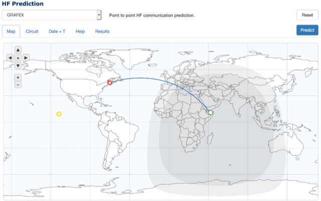 Online HF Communication prediction system provided by the Australian Governament Buerau of Metereology allow to predict usable frequency rage for radiocommunications between two stations allowing to specify frequency and date range. This tool allow calculation with different methods and algorithms
 -
 The Dipole Bazooka Antenna for 40 meters is a popular choice among amateur radio operators. Its design allows for easy construction using materials like RG58 coaxial cable and PVC. Measurements are calculated using specific formulas; for instance, at a frequency of 7,100 MHz, the total length is approximately 19.74 meters. This antenna offers a performance range of 97% to 99%, with an impedance of 49 to 52 ohms. Additionally, it can handle up to 1 kW of power and requires no modifications for connection.
 -
 The DIY Power Meter project utilizes the _INA226_ high-side power monitoring chip, paired with an ATtiny85 microcontroller, to measure voltage, current, and power, displaying the results on a 128x32 OLED screen. The INA226 communicates via an I2C interface and is programmed with a calibration factor based on the shunt resistance and current register LSB. The project is designed to handle a maximum current of 500mA using a 0.16ohm shunt resistor, which can be adjusted to a 0.2ohm resistor, reducing the full-scale current range to 409mA with a resolution of **12.5uA**. The shunt resistor dissipates only 33mW at maximum current, making 1/4 watt resistors suitable for the setup. The PowerMeter.ino sketch configures the shunt resistance and maximum design current, automatically calculating the calibration factor. The project can be prototyped on a breadboard using an Arduino Uno, employing the Wire library for INA226 and OLED communication, and the u8g2lib library for the OLED display. For the ATtiny85 version, the Adafruit-TinyWireM and Tiny4kOLED libraries are used. The power meter is independently powered by a 3V CR2032 cell, with power switching options including manual switches or DC switched jacks. The low-side n-channel MOSFET switch configuration is tested but introduces voltage drop issues, making manual switching a more reliable option until a suitable DC switched jack is found. DXZone Technical Profile: INA226 | ATtiny85 | OLED Display | Power Meter
 -
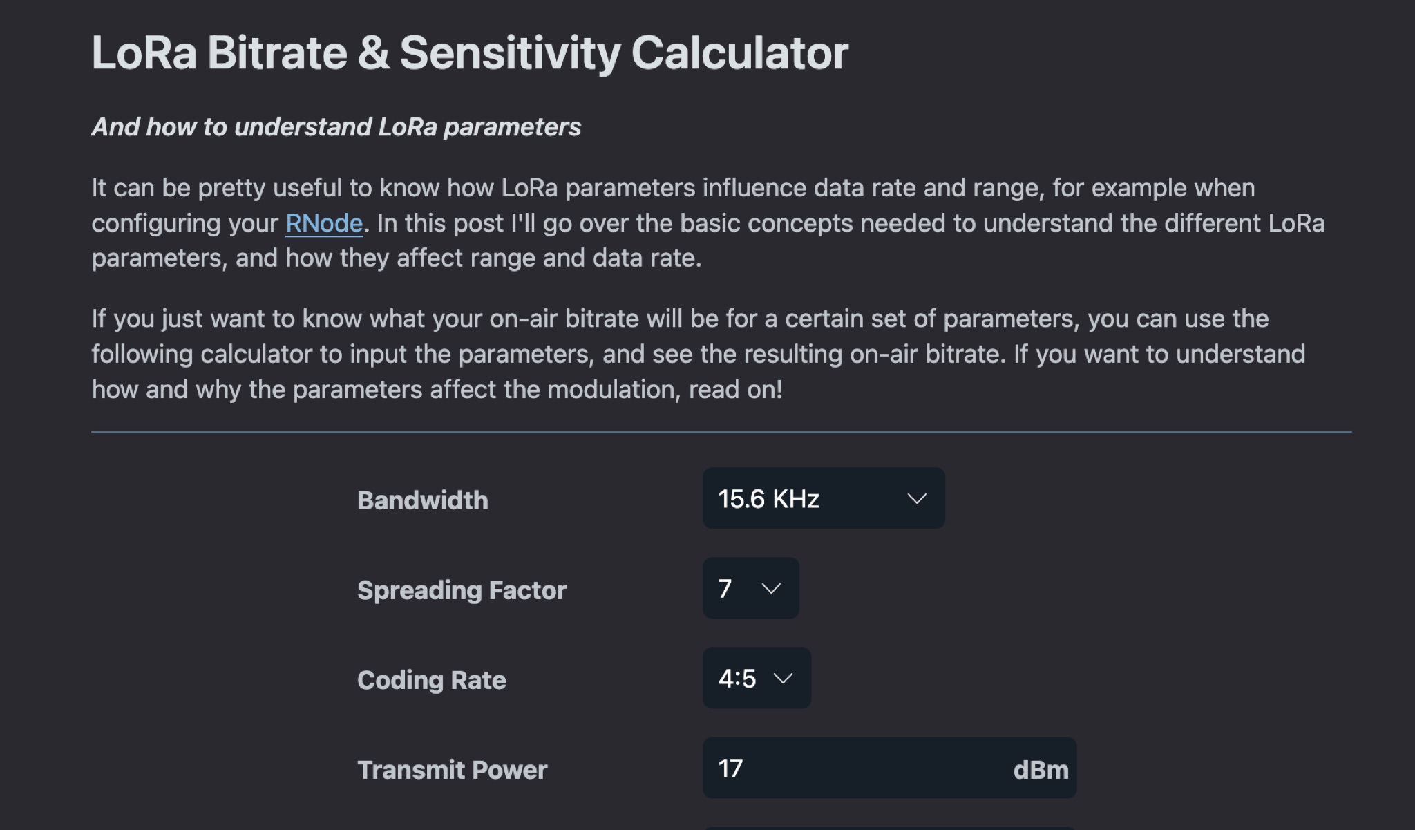 This article explains how LoRa parameters impact data rate and range when setting up a LoRa transceiver. It covers the basic concepts needed to understand different LoRa parameters and their effects on modulation. By adjusting parameters, you can achieve fast data transfers or extend transmission range. The post also offers a calculator to determine on-air bitrate based on input parameters. Understanding LoRa parameters is crucial for optimizing performance and achieving desired communication outcomes.
 -
 This article explores the powerful features of AutoEZ as an Excel application working with EZNEC antenna modeling software. The article demonstrates how variables, equations, and formulas enable versatile antenna design and automatic optimization. Through practical examples including dipoles, inverted vees, delta loops, and monopoles, the author shows techniques for achieving resonance, implementing transmission line resonators for broadbanding, and optimizing antennas across frequency ranges. The step-by-step demonstrations cover unit conversion, coordinate calculations, segmentation considerations, and SWR optimization. This practical guide illustrates how AutoEZ extends EZNEC's capabilities, making complex antenna modeling more efficient and accessible.