Search results
Query: the on line antenna mode
Links: 88 | Categories: 0
-
 The G5RV antenna, with an overall length of **31.10m (102ft)**, functions as a 3/2-wave on 20 meters when installed horizontally at 12m (39ft), exhibiting a resonant frequency of 14.150MHz and an approximate resistance of 80 ohms. Its 10.36m (34ft) stub line, designed as a 1/2-wave on 14.150MHz with a 0.97 velocity coefficient, acts as an impedance transformer across other bands, aiming for multiband operation without traps. On 20m and higher frequencies, the G5RV demonstrates improved gain compared to a standard dipole, attributed to the _collinear effect_ from multiple 1/2-waves along the wire. The original design sought a multiband solution for limited spaces, often requiring an Antenna Tuning Unit (ATU) for effective operation across bands like 80, 40, 30, and 20m, particularly with modern solid-state PAs. Variants, such as the F8CI modification, incorporate a 1/4 current balun at the stub line's base for symmetrical-to-asymmetrical transition, known as a _remote balun_. Proper flat-top or inverted-V installation is critical for maintaining symmetry and collinear gain, with inverted-V apex angles below 120° progressively diminishing higher-band performance.
 -
 Constructing a 2.4 GHz high-gain _cantenna_ for wireless networks is detailed, providing a practical approach to extending WiFi range. The author, WB8ERJ, shares insights into building these devices, noting their application in amateur radio for projects like Hinternet or HSMM (High-Speed Multimedia) networks. The article outlines the necessary components and steps, emphasizing the DIY aspect for hams interested in digital modes and local area networking. The resource explains how to determine the correct probe placement within the can, a critical dimension for optimal performance at 2.4 GHz. It references specific measurements, such as the 1.25-inch distance from the can's bottom, derived from calculations for the 2.4 GHz band. This precision ensures the antenna functions effectively for its intended purpose of signal amplification. Readers gain actionable knowledge for fabricating a functional antenna from common materials, suitable for experimentation or practical deployment in a ham shack or field environment. The focus remains on the hands-on construction and the measurable results of improved signal strength.
 -
 Presents the official online presence for Yaesu, a prominent manufacturer of radio communication equipment. The site details their extensive product lines, encompassing amateur radio transceivers, antenna rotators, tuners, amplifiers, and various accessories like microphones, speakers, and power supplies. It functions as a central hub for product information, specifications, and support resources. The resource categorizes its offerings across several key areas, including **Digital Mobile Radio (DMR)** solutions, HF/VHF/UHF transceivers, and specialized receivers and scanners. Each product section typically includes model numbers, feature highlights, and often links to manuals or technical documentation, providing hams with essential data for equipment selection and operation. Beyond amateur radio, the site also covers Yaesu's contributions to aviation and marine radio sectors, illustrating the company's broader scope in wireless communication technology. It serves as a direct portal for accessing manufacturer-provided details, ensuring accuracy and currency for those researching Yaesu gear.
 -
 The **Extended Double Zepp** (EDZ) antenna, a simple wire design, is presented as a means to achieve 3-4 dB of gain on 10 meters, with an overall length of just 43 feet. This resource, authored by WB3HUZ, details several gain antennas suitable for the 29 MHz AM segment, all modeled using EZNEC software at 30 feet above ground. Other designs include a compact rectangular loop, offering more gain than the EDZ and a lower take-off angle, and the **Lazy H**, a bidirectional antenna providing 6 dB gain, which is also workable on 20, 17, 15, and 12 meters. The Bisquare, a diamond-shaped open-top loop, is also featured, providing approximately 4 dB gain and requiring only a single support. These designs are primarily fed with ladder line or open-wire line to simplify matching, though a coax feed option for the EDZ is shown for 10-meter-only operation. The Lazy H, for instance, requires about 16 feet of open-wire line for its half-wavelength elements spaced a half-wavelength apart. An enhanced EDZ Lazy H variant is also discussed, achieving an additional 1-2 dB gain by extending element length to 1.28 wavelengths and increasing spacing to 0.64-0.75 wavelengths. The Bisquare, while primarily a 10-meter antenna, can be adapted for 20 meters by closing the top connection.
 -
 Amateur radio operators often seek reliable equipment for various modes and bands, from QRP operations to high-power DXing. Historically, Ten-Tec has been a notable manufacturer in the amateur radio market, known for its range of products including HF and VHF transceivers, RF amplifiers, and antenna analyzers. Their product line also encompassed specialized items such as QRP transceivers and kits, catering to enthusiasts of low-power communication, and antenna tuners for impedance matching. The company's offerings included test equipment vital for shack setup and maintenance, like SWR meters and RF analyzers, which assist in optimizing antenna systems and ensuring efficient power transfer. Additionally, Ten-Tec provided various accessories and components, supporting both commercial products and homebrew projects. The brand was recognized for its _made in the USA_ manufacturing, appealing to operators who prioritize domestic production. While the website currently displays limited product information, it mentions upcoming items like the _MODEL 594 PHOENIX_ and the _Tune-A-Tenna_, indicating potential future product releases.
 -
 Determining the actual need for an antenna tuner often hinges on the specific antenna and feed line configuration in use. While many hams believe a tuner is always essential, its primary role is to present a 50-ohm impedance to the transceiver, not to "tune" the antenna itself. For instance, a resonant dipole fed with _coaxial cable_ at its design frequency typically requires no tuner, as the feed line impedance closely matches the radio's output. However, operating a non-resonant antenna, or using a resonant antenna on multiple bands, frequently necessitates a tuner to manage high Standing Wave Ratio (SWR) on the feed line. The article clarifies that a tuner placed at the transceiver only matches the radio to the feed line, not the antenna to the feed line. For maximum efficiency with a non-resonant antenna, an _automatic antenna tuner_ (ATU) or a remote tuner placed at the antenna feed point is often more effective, minimizing losses in the feed line. The discussion also touches on the practical implications of SWR, noting that modern transceivers often fold back power at high SWR, making a tuner a practical necessity to achieve full output power, even if the antenna itself is not perfectly matched.
 -
 Presents the KE4UYP linear-loaded vertical antenna design, which introduces very little loss on 80 or 160 meters, achieving an overall radiation efficiency of 80% to 85%. This design addresses common pitfalls of traditional base-fed verticals by placing the majority of the current at the top of the antenna, eliminating the heavy reliance on extensive ground radial systems. The author's initial 10-meter model, only three feet tall, yielded 5/9 signal reports to Anchorage, AK, and Europe, confirming its effectiveness. The antenna incorporates both vertically and horizontally polarized radiators, with a 1/4 wavelength horizontal counterpoise located at the feed-point, near the top, to create an almost totally omnidirectional pattern with high wave angle horizontally polarized radiation. This dual polarization ensures even illumination across all take-off angles, making it effective for both local contacts and **DXing**. The vertical element is linear loaded, adding capacitance reactance and making it longer than the horizontal element to achieve resonance and raise the feed-point impedance to 50 ohms. Fine-tuning the antenna requires careful adjustment, as tower reactance can vary. The article suggests starting with 80 feet for 80m and 170 feet for 160m for the vertical wire, then trimming for resonance. Bandwidth specifications include 300 kHz under 2:1 **SWR** on 80m and 100 kHz on 160m when suspended between trees, or 150 kHz on 80m when side-mounted on a tower.
 -
 Demonstrates the construction and on-air performance of the _NB6Zep_ antenna, a modified 20-meter Extended Double Zepp design optimized for multi-band operation from 40 through 10 meters. The resource covers basic design principles, including dimensions of 66 feet horizontal and 5 feet vertical elements, and specifies open ladder line or TV twin lead for the transmission line. It details material selection for low-cost wire antenna construction, such as 18 AWG wire for the legs and ceramic or plastic insulators, along with practical tips for soldering connections and insulating against moisture. The author, NB6Z, shares insights from extensive _EZNEC_ modeling to optimize the antenna's total length for a 40-meter half-wave dipole footprint and feed line length for direct tuner connection. The article presents field results, including successful _PSK31_ contacts from Oregon to the East Coast on 40 and 30 meters with 50 watts, even at a low height of 6 feet. It provides detailed performance characteristics for each band, noting the _NB6Zep_'s highest gain (over 3 dB) and sharp, medium-angle lobes on 20 meters, which yielded strong DX reports to locations like Korea, Japan, and Argentina. For 17 and 15 meters, it describes a butterfly-like pattern with broad lobes, while 12 and 10 meters exhibit narrow, directional lobes in an "X" configuration. The author also shares personal experiences operating successfully for over a decade in an antenna-restricted environment using the NB6Zep and other stealth wire antennas.
 -
 Presents a catalog of **QRP** transceivers, antenna tuners, and related accessories for amateur radio operators. The product line includes the ZM-2 antenna tuner, designed for efficient impedance matching across HF bands, and the NW-series QRP transceivers, offering low-power CW operation. Additionally, the site details various ladder line insulators and specialized connectors, emphasizing robust construction for field deployment and home station use. Each product listing provides specifications, operational parameters, and pricing information. Compares the features of different **QRP transceiver** models, such as the NW-40 and NW-20, highlighting their respective band coverage and power output capabilities. The ZM-2 tuner's performance is detailed with typical SWR reduction figures for various antenna types, demonstrating its utility for portable and fixed stations. Customer testimonials and product images illustrate the practical application and build quality of EMTECH's offerings, providing insights into their durability and ease of integration into existing amateur radio setups.
 -
 manufactures and distributes HF, VHF, UHF and SHF equipment covering 10MHz. - 47.0GHz. Our products include: Wireless LAN / WAN Bidirectional Linear Amplifiers, Low Noise Preamplifiers - LNA's, RF Linear Amplifiers, Relays, Transverter Systems, Frequency Translation Systems, Downconverters, Antennas, Parabolic Dishes, Coaxial Cable, Relays, Antenna Switches, Microwave Test equipment, PC controlled Receivers, Microwave Linear Amplifiers including models for Telemetry, Wireless, and CDMA applications.
 -
 Demonstrates the construction and performance of an updated ZS6BKW multiband dipole, a variant of the _G5RV_ antenna, specifically designed for HF operation. The article details a real-world installation using 13.5m copper wire elements and 12.2m of 450 Ohm ladder line, configured as a sloping inverted-V with the apex at 10m and ends at 4m above ground. It covers the critical aspect of impedance matching, incorporating an 8-turn choke balun at the feedline transition to RG-58U coax to mitigate RF common mode current. Measurements confirm favorable SWR readings below **1.3:1** on 7.1 MHz, 14.11 MHz, 18.06 MHz, and 24.8 MHz, indicating effective resonance across 40m, 20m, 17m, and 12m bands. The installation also shows usable SWR dips on 3.55 MHz (5:1), 29.02 MHz (2:1), and 50.84 MHz (3:1), extending its utility to 80m, 10m, and 6m with an antenna tuning unit. Initial on-air results report clear reception of stations over **5000km** away, validating its DX potential.
 -
 The Windom is an Off-center wire multiband Antenna. The old version was fed just by a single-wire connected on 1/3 of antenna's overall length or with an open-line feeder (later versions). Here is another model with coaxial feeder, which is compatible with Solid States - 50 Ohm output transceivers .
 -
 Selecting an appropriate antenna system for shortwave broadcasting involves evaluating various types based on performance, cost, and operational parameters. This resource details the critical specifications for broadcast antennas, including average and peak power ratings, directivity, takeoff angle (TOA), horizontal beamwidth, and gain, emphasizing that a 100-kW transmitter requires an antenna rated for 150 kW average and 400 kW peak. It clarifies that low TOA signals travel thousands of kilometers, while high TOA is for local coverage, and nearly all modern shortwave broadcast antennas are horizontally polarized. The article explores specific antenna types, such as Log-Periodic Antennas (LPAs), which offer wide frequency ranges (e.g., 2-30 MHz) and directional patterns with 11 dBi gain, costing from $20K to over $100K for multi-curtain versions. Dipole arrays, also known as curtain antennas, are prevalent in international broadcasting, featuring steerable beams (±15° and ±30°) and mode-switching capabilities to alter TOA, with high/low pairs costing over $1 million. Fan dipoles are noted for omnidirectional patterns, smaller size, and lower cost for low-power applications, while rhombics, though simple, require resistive termination and incur several dB of I2R losses. Balun considerations are crucial, as most communications baluns are not rated for the higher average and peak powers of AM broadcast transmitters. Modern shortwave antennas utilize durable materials like Alumoweld wire rope for radiators and support elements, avoiding copper, fiberglass, or materials prone to stretching or deterioration. Feeder systems for high-power stations often require tapered-line baluns to convert 50-ohm unbalanced power to 300-ohm balanced for connection to the antenna.
 -
 One common challenge in antenna systems is mitigating common-mode current on the feedline, which can distort radiation patterns and introduce RF in the shack. This project details a 1:1 balun design that ingeniously avoids traditional ferrite beads, often a costly component, by substituting them with steel wool. The steel wool, when integrated into the balun's construction, effectively attenuates unwanted RF on the outer braid of the coaxial cable, ensuring that the antenna radiates efficiently and as intended. The construction involves winding coaxial cable through a PVC former, with the steel wool strategically placed to provide the necessary common-mode impedance. This method offers a practical and economical alternative for hams looking to build effective baluns without the expense or availability issues associated with ferrite cores. The design principles focus on creating a balanced feed to the antenna, crucial for optimal performance of dipoles and other balanced radiators. Experimentation with such designs can lead to improved field results, particularly for those operating with limited budgets or seeking innovative solutions for their antenna systems. The simplicity of using readily available materials like steel wool makes this a compelling build for many radio amateurs.
 -
 A 40-meter reversible _Moxon rectangle_ antenna project details its construction and performance, featuring 51-foot long sides and 7.7-foot turned-in sections. The design incorporates a 16.5-foot boom, with elements spaced 1.1 feet apart, constructed from #14 covered wire. It utilizes two double-pole relays for switching between NE and SW directions, achieving F/B ratios up to 40 dB on CW and 30 dB on SSB, with distinct reflector stub settings for each mode. This antenna replaced a full-size 2-element Yagi, demonstrating comparable forward gain while offering superior F/B ratios and directional flexibility. _EZNEC_ modeling indicates only 0.2 dB less forward gain than the Yagi. The system uses no baluns, relying on half-wave feedlines and switched stubs for impedance matching. The antenna is tree-supported at 45 feet, with its effective radiation height modeled at 80 feet due to local terrain, enhancing its performance over a nearby lake.
 -
 Over 75 years of engineering expertise underpins Bird Electronic's offerings in RF power measurement, critical for maintaining peak performance in amateur radio stations and professional communication systems. The company specializes in a range of test equipment, including wattmeters, SWR meters, and antenna analyzers, essential for optimizing antenna systems and ensuring efficient power transfer. Their product line extends to various RF components such as filters, cables, and connectors, all designed to meet stringent technical specifications for reliability and accuracy across diverse frequency bands. Bird Electronic's instruments, like the _Bird 43_ Thruline Wattmeter, are widely recognized for their robust construction and precise measurement capabilities, providing hams with confidence in their station's operational parameters. These tools enable accurate assessment of forward and reflected power, SWR, and modulation characteristics, which are vital for troubleshooting and maximizing radiated power. The company's commitment to innovation ensures that its products remain relevant for modern RF challenges, from HF through microwave applications, supporting both traditional analog and advanced digital modes.
 -
 The Buddipole website showcases a range of portable amateur radio antenna systems, including the **Buddipole**, Mini-Buddipole, Buddistick PRO, and BuddiHEX, designed for rapid deployment and multi-band operation from 40 meters to 2 meters. Each product page details specifications, operational modes (dipole or vertical), and compatible accessories like tripods, masts, and baluns. The site also features portable DC power management systems such as the PowerMini 2 and PowerPlus, which include integrated battery chargers and solar controllers, catering to off-grid or field day setups. Instructional videos demonstrate antenna assembly, tuning, and deployment techniques for various configurations, including the VersaTee vertical and Mini-Buddipole. Customer testimonials and DXpedition highlights, such as operations from Montserrat (VP2M) and Dominica (J38), provide real-world examples of the equipment's performance in challenging environments. The company, established in 2001, emphasizes modularity, versatility, and efficiency in its product line, all manufactured in the USA. Shipping information, a 30-day return policy with no restocking fee, and contact details for their Heber City, Utah facility are clearly presented. The site serves as a direct sales portal, offering a comprehensive catalog of antennas, power solutions, and components for portable amateur radio enthusiasts.
 -
 Theory, Modeling, and Practical Applications By W5JCK, presentation in PDF File. This presentation focuses on Near-Vertical Incidence Skywave (NVIS) antennas, which are crucial for short-range radio communications, particularly in military and emergency contexts. It explores NVIS theory, antenna models, and installation criteria while debunking common myths about reflectors. Key topics include usable frequency bands, optimal installation heights, and the impact of soil quality on performance. The presentation outlines the best bands for daytime and nighttime use, emphasizing the importance of understanding propagation characteristics to enhance communication effectiveness within 200 to 300 miles.
 -
 The document details the optimization and construction of the _Maria Maluca_ antenna, a compact 6-band (20m-6m) directional beam. It presents a comparative analysis of shortwave antenna principles, highlighting the efficiency gains achieved by using an open feeder line and tuner as a resonant unit, contrasting this with the losses associated with traps or capacitive loads in multiband antennas. The resource specifically revisits an older South American 2-element design for 10, 15, and 20 meters, applying modern NEC-based software to develop a six-band version. Performance data is meticulously tabulated, showing impedance, free space gain, gain at 12m height, elevation angle, and front-to-back (F/B) ratio for each band from 20m through 6m. For instance, on 15m, the antenna achieves 5.1 dBd free space gain and 13.72 dB F/B ratio. The construction section provides practical guidance on element assembly using aluminum pipes and hose clamps, detailing the use of a heavy-duty glass fiber reinforced polyamide rod for electrical separation and bending strength. It also specifies the use of 450-ohm _Wireman_ line CQ 552 for the transmission line. The document includes diagrams for rod fixing, an air-wound balun, and a vertical elevation diagram for the 15m band, illustrating its DX qualification. It also discusses the antenna's suitability for portable and expedition operations, noting its compact transport dimensions (max 1.50m length, 12 lb weight) and quick assembly time (under 15 minutes). The author, Dipl.Ing. Helmut Oeller, DC6NY, is identified as a source for material kits.
 -
 This resource details the computer-optimized design of the _ZS6BKW_ multiband dipole, an evolution of the classic _G5RV_ antenna. It begins by referencing the original 1958 RSGB Bulletin article by Louis Varney G5RV, explaining the operational principles of the G5RV's flat-top and open-wire feedline on 20m and 40m, noting its impedance transformation characteristics for valve amplifiers of that era. The article then transitions to the rationale for optimizing the design for contemporary solid-state transceivers requiring a 50 Ohm match. The core of the project involves using computer modeling to determine optimal lengths for the flat-top and matching section, aiming for a VSWR of less than 2:1 on multiple HF bands. It discusses the process of calculating feedpoint impedance based on antenna length and frequency, referencing professional literature from Professor R.W.P. King at Harvard University. The analysis also considers the characteristic impedance (Z(O)) of the open-wire line, identifying a broad peak of adequate values between 275 and 400 Ohms. Specific design parameters for the improved ZS6BKW are presented, including a shorter flat-top and a longer matching section compared to the original G5RV, with a velocity factor of 0.85 for the 300 Ohm tape. The article confirms acceptable matches on 7, 14, 18, 24, and 28 MHz bands when erected horizontally at 13m, and also discusses performance in an inverted-V configuration, noting frequency shifts. The author, Brian Austin ZS6BKW, emphasizes the antenna's suitability for modern 50 Ohm coaxial cable without a balun.
 -
 Operating a ZS6BKW antenna often involves understanding its lineage from the _G5RV_ design, with specific modifications by ZS6BKW to optimize performance on several bands. Through computational analysis and field measurements, the antenna's dimensions were refined to allow operation on 10, 12, 17, 20, and 40 meters without an antenna tuner. For 80, 30, and 15 meters, a tuner is necessary, though efficiency on 30 and 15 meters is noted as not particularly high. The physical configuration consists of two 13.755-meter radiating elements fed by a 12.20-meter section of 450-ohm ladder line. Tuning the antenna on the 20-meter band is critical, and any deviation in the ladder line's characteristic impedance necessitates recalculating the element lengths. The design is also referenced in the 12th edition of _Rothammel's Antennenbuch_, page 219. Proper common mode current suppression is crucial at the transition from ladder line to coaxial cable. This can be achieved with a common mode choke, such as several turns of coax wound into a coil or over a ferrite toroid like an Amidon T130. While a 1:1 balun is an option, it may introduce issues.
 -
 This resource details the conversion of an 80m elevated vertical antenna to include 160m operation, focusing on a relay-switched design over a trap-based approach. It presents specific feedpoint impedance values, such as **32 ohms** for 80m and **14 ohms** for 160m, and discusses the challenges of SWR drift encountered with the prior trap system during RTTY contesting. The article thoroughly explains the design choices for elevated radials, referencing _N6LF QEX data_ to debunk common myths regarding radial length and height, demonstrating that non-resonant radials can offer superior current uniformity. The construction section provides practical insights into building the vertical, including guying strategies, material selection from scrap pipe, and weatherproofing the relay assembly. It highlights the use of a common mode choke for the relay switching line, measuring approximately 5K ohms on both 160m and 80m, and details the L/C matching network's role in achieving a 50-ohm match at the end of a 300-foot RG-11 run. The author describes a precise VNA-based radial trimming procedure, achieving resonant values within a 3 KHz range. The content emphasizes the practical application of theoretical antenna principles, particularly concerning the interaction between the vertical element, cap hats, and the matching network. It offers a candid assessment of component selection, such as using junkbox parts and acknowledging the need for future upgrades to static drain resistors. The article serves as a comprehensive case study for advanced antenna builders tackling multi-band vertical designs.
 -
 The page discusses Axial-Mode Helical Antennas, focusing on turning helical antennas over perfect ground and modeling helices in NEC-2 for optimized design. It covers topics such as high-gain performance, broadband, impedance matching, radiation pattern, feedline, balun, near field, far field, and DIY applications.
 -
 Complex CAD and Optimization Software for Waveguide, Coax, Combline and Antenna components design and antenna modelling
 -
 Demonstrates the product line of _LZ Antenna Ltd._, a Bulgarian manufacturer specializing in amateur radio antennas and custom electronic devices. The company focuses on robust, high-quality HF multiband Yagi and vertical antennas, leveraging over 20 years of experience from founder Georgi Georgiev in radio amateur development. Featured models include the LZA 8-4, LZA-10-3, and the LZA-7-3A WRTC 2022, alongside various rotary dipoles like the LZA1 40/30m. Provides specifications for several Yagi antennas, such as the LZA-9-5, LZA-13-7, and LZA-6-3 (a 6-element, 3-band design). The company emphasizes applying "leading edge technology" to high-frequency communication equipment production, with products designed for durability and performance. The LZA-10-5 Yagi offers **12.5 dBi** gain on 10m, while the LZA-13-7 provides **13.2 dBi** on 20m, showcasing competitive gain figures for DXing and contesting.
 -
 The **HFRadioSales.au** resource provides a commercial outlet for amateur and commercial radio operators seeking HF SSB equipment and related services. It focuses on the Australian market, offering new and refurbished transceivers, antennas, tuners, and a wide array of spare parts for brands like Codan, Barrett, and Qmac. The site details its role as a licensed dealer for new Barrett Communications and Codan radio and antenna systems, including specific models such as the Barrett 4050, 2050, and 950, and Codan Envoy and NGT series. This platform supports various applications, including vehicle, 4WD, outback, marine, and base station setups, catering to networks like HF Radio Club, VKS737, and RFDS. It also features commercial-grade antennas from Bushcomm, such as the BBA100C and SWC100, available for fast shipping from their Queensland warehouse. The site includes an FAQ section with general information on mobile HF communications in Australia and timelines for specific transceiver models.
 -
 Yagi-logper is a linux GPL program to model a Yagi or Log-periodic antennas with horizontal cylindrical dipoles.
 -
 SimSmith is a highly interactive, real time Smith chart graphing program. Circuits are constructed using drag-n-drop. Load files can be imported from the EZNEC and CocoaNEC antenna simulation software and from the AIM4170 and miniVNApro antenna analyzers. Circuits and load files can be of any size. Key Features: SimSmith is one of the few Smith chart packages which models transmission line losses. SimSmith also allows the description of circuit elements using algebraic equations. SimSmith has only one screen and allows the screen to be resized to increase workspace or readability.
 -
 The G5RV multiband HF antenna, designed by Louis Varney (G5RV) in 1946, is a popular compromise antenna offering good overall performance on most HF bands when paired with an external antenna tuner. The basic full-size G5RV measures 102 feet across the top for 80 through 10 meter operation and is fed at the center via a 34-foot low-loss feed-stub. This interaction between the radiating section and the feed-stub facilitates matching across 80-10 meters with a standard tuner, often eliminating the need for ladder line directly to the shack. The antenna's design center frequency is 14.150 MHz, configured as a 3/2-wave dipole on 20 meters, with its 102-foot length derived from long-wire antenna formulas. Construction details emphasize the matching section, which can be open wire, ladder line (window-type), or TV twin lead. Each type has a specific velocity factor (VF) affecting its physical length for an electrical half-wave on 14 MHz; for instance, open wire requires 33.7 feet (VF 0.97), ladder line 31.3 feet (VF 0.90), and TV twin lead 28.5 feet (VF 0.82). The article provides formulas for calculating these lengths and discusses the antenna's behavior on individual bands, from 3.5 MHz where it acts as a shortened dipole, to 28 MHz where it functions as two three-half-wave long-wire antennas fed in-phase. Practical construction notes include recommendations for vertical descent of the matching section, sealing the coax junction, providing strain relief, and winding a coaxial choke coil to mitigate common mode current. The resource also presents dimensions for double-size (204 ft) and half-size (51 ft) G5RV versions, along with their corresponding matching section lengths for various line types, making it a versatile reference for hams considering this classic wire antenna.
 -
 Accurately determining an antenna's feedpoint impedance is crucial for optimal performance, especially when experimenting with new designs or making adjustments. While SWR meters provide basic information, a full complex impedance measurement reveals the resistive and reactive components, which are essential for proper matching. Modern antenna analyzers, like the _Palstar ZM30_ or MFJ259B, simplify this task, but measurements taken through a transmission line require careful interpretation due to impedance transformation. This resource details a calibration method to precisely account for the effects of the feedline. It explains how a transmission line can significantly alter the measured impedance, illustrating this phenomenon with a Smith Chart example where an 80m antenna's [22 + j6] Ohms feedpoint impedance transforms to [82 + j45] Ohms after a 10m line. The guide demonstrates using a transmission line calculator applet, such as the one by W9CF, to reverse this transformation. It outlines the process of calibrating a specific length of RG174 coax, showing how an initial 26ft estimate was refined to **25.85ft** to accurately predict a known 22 Ohm load, significantly improving accuracy over uncalibrated results.
 -
 DF9CY implementation of W1HIS suggestion of inserting a common mode choke into a 40m antennas feed-line.
 -
 The ZS6BKW multiband antenna, an optimized variant of the classic G5RV, features a 102-foot (31.1 m) horizontal span and a 39.1-foot ladder line matching section. This design, derived by G0GSF (formerly ZS6BKW) in the early 1980s using computer programs and _Smith charts_, aims for improved SWR across multiple HF bands compared to its predecessor. Construction details specify Wireman 554 ladder line and #14 AWG THHN copper wire for the radiators, with precise instructions for determining the velocity factor (VF) of the ladder line using an antenna analyzer or dip meter, ensuring accurate physical length for the matching section. The radiator length is electrically 1.35 wavelengths for the 20-meter band, requiring careful trimming during tuning. Field measurements with an _AIM-4170C_ analyzer by KI4PMI and NC4FB demonstrated good SWR curves and bandwidth on 6, 10, 12, 17, 20, and 40 meters. The antenna was deemed unusable on 15 and 30 meters due to very high SWR, but an LDG AT-100PRO autotuner successfully brought 6 and 80 meters into tune. Contacts were made on 80, 40, 20, and 17 meters, including a **17-meter** contact to Spain. EZNEC models for 80-6 meters are provided, along with an AutoEZ model by AC6LA, which predicted good SWR for 80-10 meters. W5DXP's modifications for an all-band HF ZS6BKW are also referenced.
 -
 This resource details the four primary functions of a ground system: lightning energy dispersion, equipment safety, RF return path provision for end-fed antennas, and management of induced RF currents. It clarifies that a ground system's effectiveness varies depending on its specific function, noting that a good lightning ground might not be an effective RF ground. The content emphasizes that proper antenna system design, including baluns and appropriate feedline lengths, often negates the need for an RF station ground to mitigate common mode currents or RFI in the shack. The article quantifies lightning energy, stating its peak is in the dozens or hundreds of kilohertz, with damaging energy extending to hundreds of megahertz, and currents reaching thousands of amperes. It recommends solid, wide, smooth copper surfaces for ground leads to achieve low impedance across a wide frequency range. The author, W8JI, shares practical insights from his station, which includes two 300-ft towers and four 130-ft wire verticals, detailing his use of common point grounds and _DX Engineering RR-8 HD_ antenna switches for lightning protection without coaxial surge protectors. Specific examples of antenna systems prone to common mode current problems are listed, such as random wire antennas without proper feedline lengths and off-center fed dipoles. The text also explains how a ground screen or radial system can reduce local noise sensitivity for vertically polarized antennas by covering the lossy earth.
 -
 Understanding Baluns. This article explores some simple antenna system configurations and the effect of key system components, connections and dimensions on feed line common mode current.
 -
 The ZS6BKW multi-band antenna, an optimized variant of the classic G5RV, is presented with detailed construction and tuning instructions. This resource outlines the antenna's design principles, which were developed by _Brian Austin (G0GSF)_ using computer programs and Smith charts to achieve optimal dimensions. It provides specific guidance on calculating and adjusting the lengths of the radiators (L1) and the matching ladder line (L2), emphasizing the critical role of velocity factor (VF) in achieving resonance. The article includes a step-by-step procedure for empirically determining the VF of ladder line using an antenna analyzer, ensuring accurate physical lengths for the matching section. It details the tuning process for the radiators, offering practical tips for incremental adjustments to achieve the best SWR curve. The resource presents SWR measurement results obtained with an _AIM-4170C_ analyzer across multiple bands, alongside predicted SWR graphs from an AutoEZ model. It confirms successful contacts on 80, 40, 20, and 17 meters, including a **17-meter DX contact** to Italy. EZNEC and AutoEZ models for the ZS6BKW antenna, covering 80 through 6 meters, are provided for download, allowing further analysis and customization. The document specifies component details, such as the use of Wireman 554 ladder line and #14 AWG THHN copper wire, and discusses the antenna's performance characteristics, noting high SWR on 15 and 30 meters but successful tuning on 6 and 80 meters with an external tuner.
 -
 Demonstrates various practical amateur radio projects and technical discussions through video episodes. One episode details cutting and retuning a _1/4 wave shorted stub_ from 101.7 MHz to 107.5 MHz to safeguard a transmitter's driver stage, alongside insights into advanced _160-meter antenna systems_ like eight-circle arrays and beverage antennas. Another segment covers upgrading firmware on an _ATS-20+_ receiver using AverDudes for improved display and functionality, and a detailed guide on using D-Star DR mode on an _ICOM ID-52A_ for international repeater programming. Additional content includes a deep dive into _OpenHamClock_ as a potential replacement for the HamClock project, updates on _Raspberry Pi 5_ running Trixie OS, and a review of the Choyong LC90 Internet radio with AI integration. The series also features "Ham College" episodes, which meticulously prepare viewers for the Technician Exam by covering topics such as antenna and transmission line measurements, SWR interpretation, and the functions of basic electronic components like rectifiers, relays, and transistors. Practical advice on coaxial cable characteristics, dummy loads, and proper soldering techniques is also provided.
 -
 Protecting amateur radio equipment from transient overvoltages requires robust lightning and surge protection, which is the focus of Electronic Specialty Products. The company provides various devices, including coaxial lightning arrestors for antenna feedlines and surge protectors for AC power lines and data circuits. These devices are engineered to divert high-energy surges, such as those caused by direct or indirect lightning strikes, away from sensitive transceivers, amplifiers, and computer components, thereby preventing catastrophic damage. Key products include the _Coaxial Lightning Protector_ series, designed for various impedance levels and frequency ranges up to 3 GHz, and the _AC Line Surge Protector_ for shack power distribution. Effective deployment of these protection devices can significantly reduce the risk of equipment failure and ensure operational continuity during severe weather. For instance, a properly installed coaxial arrestor can handle peak currents of **20 kA**, while AC line protectors offer clamping voltages typically below 400V. Comparing different models reveals varying levels of insertion loss and return loss, with some coaxial units exhibiting less than 0.1 dB loss at 500 MHz, making them suitable for high-performance HF and VHF/UHF operations. Integrating these components into a comprehensive grounding system is crucial for achieving maximum protection against both common-mode and differential-mode surges.
 -
 Benelec Pty Ltd specializes in the design and manufacturing of **antennas** and RF components, covering a broad frequency range from 0.002 GHz to 8 GHz. Their product line includes Land Mobile Radio Antennas, such as HF 2-30MHz, VHF 40-180MHz, and UHF 200-520MHz models, alongside specialized Military Antennas for dismounted, UxS, C2, and EW applications. The company also produces Cellular Antennas, including 4G/5G and GPS/GNSS types, and Marine Antennas for both vessel-mounted and fixed-site installations. Additionally, Benelec offers a comprehensive range of coaxial cables, connectors like N-Type and SMA, and various radio accessories. The company's offerings extend to RF components such as duplexers, diplexers, and 50 Ohm loads, as well as DAS components like directional couplers and hybrid combiners. Benelec provides EMP and lightning protection solutions, including 1/4 Wave Stub protectors and replaceable GAS capsules. Their product catalog also features P25, DMR, and FM Analog radios, along with portable and mobile radio accessories like batteries, chargers, and cabled headsets. The company supports various sectors with robust communication solutions.
 -
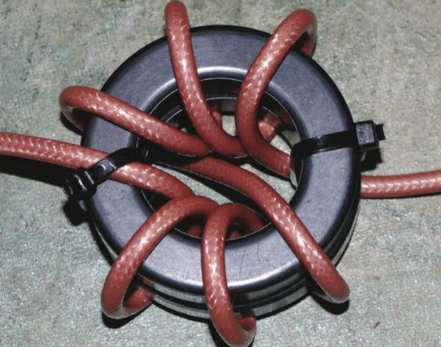 May 2015 Radcom Article on common-mode chokes that can be used for control cables, phone lines, but mostly on typical HF antenna systems. This article explain what common mode chokes does, why you meay need one, properties common mode chokes should have, how to build and measure performances.
 -
 Operating a modern amateur radio station often involves integrating various software tools, and LogHX aims to provide a unified environment for Windows users. The software facilitates comprehensive QSO accounting, allowing operators to track contacts and manage both e-QSL and traditional paper QSL exchanges, including via QSL managers or direct methods. It also offers real-time QSO preview and integrates with popular callbook data for quick lookups. LogHX supports various logbook database searches and maintains statistics for numerous awards, a critical feature for serious DXers and contesters. The program handles logbook import and export in widely used formats such as _ADIF_ and _Cabrillo_, ensuring compatibility with other logging applications. Furthermore, it interoperates with Telnet clusters and third-party ham radio software, enhancing its utility in a networked shack environment. Key functionalities include antenna rotator control, editable macros for PSK, RTTY, CW, and SSB operations, and CAT control via _OmniRig_ or direct interfaces. Embedded modules like MMVari, MMTTY, and CWServer streamline digital mode operations, while its multi-window structure allows users to customize their screen layout, preserving valuable monitor space.
 -
 Modeling compact 160 meter antennas, inverted L, half wave dipoles and linearly loaded dipole
 -
 The NB6Zep Antenna, an electrically shortened 80-meter end-fed wire, addresses space constraints for low-band operation by integrating two loading coils into a 37-foot wire. This design, modeled with _EZNEC_, explores configurations like the quarter-wave sloper and inverted-L, with the latter providing a more vertical radiation pattern and practical backyard deployment. The resource details specific coil construction, recommending 21 uH coils made from _BW coil stock #3026_ or similar, and outlines wire segment lengths for optimal tuning. Performance analysis indicates a radiating efficiency of approximately 27% with good ground conductivity, resulting in a signal typically 3-4 dB down compared to a full-size quarter-wave vertical. The antenna exhibits a narrow bandwidth, around 50 kHz, due to its high Q, necessitating a tuner for broader band operation. Feedpoint impedance is low, with ground resistance playing a critical role in achieving a usable SWR. The article emphasizes the importance of an effective ground rod at the feedpoint for proper operation and tuning, suggesting an antenna analyzer for precise adjustments. It confirms the antenna's suitability for DX, citing successful contacts from Oregon to the East Coast and Hawaii on a 160-meter variant, making it a viable option for urban operators seeking low-angle radiation on 80 meters.
 -
 The HA8TKS VHF DXCluster is an essential online resource for amateur radio operators focusing on VHF and higher frequencies. This platform provides real-time information on DX spots, allowing users to track and engage in two-way radio communications effectively. The integrated map mash-up feature enhances the user experience by visually displaying the locations of DX stations, making it easier for operators to plan their contacts and optimize their antenna setups based on geographical data. In addition to the DXCluster functionality, the site offers various HAM tools, including a QRB calculator, which helps operators determine the distance to DX stations based on Maidenhead grid locators. The platform supports multiple modes of operation, including CW, SSB, RTTY, and digital modes like FT8 and JT65. With a user-friendly interface and comprehensive data, the HA8TKS VHF DXCluster is a valuable asset for both novice and experienced operators looking to enhance their DXing and contesting activities.
 -
 Presents a construction project for a 1:1 current balun, specifically detailing the _Sorbie Balun and Bottle Choke_ design. The resource outlines the winding technique, employing 4+4 turns of mini coaxial cable on a large ferrite core, and provides insights into the physical assembly. It includes specific material recommendations, such as the type of ferrite and coaxial cable, crucial for achieving the desired impedance transformation and common-mode current suppression. The content covers the practical steps involved in building the balun, from preparing the coaxial cable to securing the windings on the ferrite toroid. It also discusses the integration of the balun into an antenna system, emphasizing its role in maintaining pattern integrity and reducing RF interference in the shack. The resource offers a clear, step-by-step approach, making the project accessible for homebrewers. Illustrations and photographs accompany the text, visually guiding the builder through each stage of construction. The article concludes with performance expectations and considerations for deployment, ensuring the constructed balun functions effectively across the intended frequency range.
 -
 Operating the _Icom IC-746_ HF/VHF transceiver often presents specific technical questions, and this resource compiles a comprehensive Frequently Asked Questions (FAQ) document in an ASCII text format. It details common inquiries and solutions related to the rig's functionality, accessories, and potential modifications. The content is structured into distinct sections addressing general information, power supplies, antennas, microphones, keyers, amplifiers, TNC integration, and optional IF filters. The FAQ provides practical guidance on topics such as configuring the internal automatic antenna tuning unit (ATU), selecting appropriate power supplies, and understanding microphone pin-outs. It also delves into advanced subjects like computer control via CI-V, wiring for PSK31 operation, and troubleshooting common issues like low S-meter readings on 2m FM or loose tuning shafts. Specific questions cover the installation of optional IF filters, comparing Inrad versus Icom filters, and optimizing filter combinations for various modes. Furthermore, the document outlines various hardware and firmware modifications, including those for increasing monitor volume, replacing LCD driver transistors, and implementing a "poor man's TCXO." It even touches upon untested modifications, such as replacing PIN diodes in the demodulator. The FAQ also lists manual errata and discrepancies, offering a robust knowledge base for IC-746 owners seeking to optimize their station or resolve operational challenges.
 -
 Operating a ham station often involves encountering radio frequency interference (RFI), RF feedback, or RF burns, which are frequently misattributed to poor equipment grounding. This resource meticulously dissects these assumptions, asserting that RF grounds on the operating desk often merely mask more significant system flaws. It identifies five primary causes for RF problems, including antenna system design flaws, proximity of the antenna to the operating position, DC power supply ground loops, equipment design defects, and poorly installed connectors or defective cables. The content emphasizes that issues like "hot cabinets" or changes in SWR when connecting a ground indicate substantial RF flowing over wiring or cabinets, a phenomenon known as common-mode current. The article provides detailed explanations of common-mode current generation, particularly from single-wire fed antennas like longwires, random wires, and OCF dipoles, which inherently present high levels of RF in the shack. It also illustrates how vertical antennas, lacking a perfect ground system, can excite feed lines with significant common-mode current. Through simulations, the author demonstrates how a dipole without a proper _balun_ can cause RF problems at the operating desk, showing current patterns and voltage distributions on feed line shields. The discussion extends to the proper application of _RF isolators_ and _ferrite beads_, clarifying their role in modifying common-mode impedance on cable shields and cautioning against their use as a band-aid for fundamental system defects. The resource advocates for correcting the actual source of RF problems, such as antenna system issues or poor connector mounting, rather than relying on internal shack grounding or isolators. It highlights that properly functioning two-conductor feed lines, like coaxial or open-wire lines, should result in minimal RF levels at the operating position, even without a desk RF ground. The author shares personal experience, noting that his stations since the late 1970s have operated without RF grounds at the desks, relying instead on proper antenna system design and feed line integrity.
 -
 How do two-wire reversible direction Beverages work, an excellent document that explains fundamentals of beverage antennas. This article details the design and performance of a reversible beverage antenna. Leveraging orthogonality between common mode and differential mode currents on a 2-wire line, this antenna facilitates independent reception from both ends. While common mode signals arrive and are summed on a transformer's secondary for common mode reception, differential mode signals induce anti-phase currents, providing individual reception. Various measurements explore impedance, transmission loss, and F/B ratio, highlighting the antenna's effectiveness and areas for improvement. Notably, increasing the antenna's height significantly improved performance.
 -
 Demonstrates the _RoMac Automatic CW Identifier 2012_ software, a Windows application designed to automate station identification and provide a tuning pulser. It can send CW identification via a sound card's audio output or by keying a radio's manual CW jack using a serial port's DTR line. The software also supports CAT commands for various Kenwood, Yaesu, Flex, and Elecraft radios, enabling automatic mode and frequency changes for ID transmission. It integrates with USB audio-capable radios like the Icom 7300 and Yaesu FT-991, simplifying connectivity with a single USB cable. The application features a fully programmable interface, adjustable CW speed from **5 to 35 WPM**, and ID intervals from **5 to 30 minutes**. The integrated "Pulse Tuner" function allows for safe amplifier and antenna tuner adjustments by sending short audio tones or rapid CW keying, with an adjustable duty cycle from 1% to 100%. It offers compatibility with a wide range of transceivers and amplifiers, and a schematic for a basic sound card interface is included for users without existing setups.
 -
 1.5 dB of matched line loss can be calculated for a given transmission line using this online tool, which employs a model calibrated from empirical data. The calculator allows radio amateurs to input specific transmission line types, such as _RG-8_ or _RG-58_, and then determine the expected signal attenuation. This is crucial for optimizing antenna system efficiency and understanding power delivery to the radiating element, especially for HF and VHF operations where feedline losses can significantly impact performance. Beyond matched loss, the calculator also provides an estimate for mismatched loss if the Standing Wave Ratio (SWR) is specified. This feature helps operators quantify the additional power loss due to impedance discontinuities between the transceiver, feedline, and antenna, which is a common concern in amateur radio installations. Accurate loss calculations are vital for effective station design and for predicting actual radiated power. The tool's utility extends to various operating scenarios, from fixed station setups to portable deployments, aiding in the selection of appropriate feedline lengths and types to minimize signal degradation. Understanding these losses is a fundamental aspect of maximizing the effectiveness of any amateur radio antenna system.
 -
 Presentation about Practical Antenna Modeling Using the NEC Codes with examples of HF wire antennas and 4NEC2. How to define and edit the models, Running the simulations, Work some examples, Variables usage, Deal with Feed Lines and ground