Search results
Query: wound antenna
Links: 33 | Categories: 0
-
 140 feet of insulated wire, the first half of which (70 feet) is space wound on an insulated tube.
 -
 Details the construction of a **multiband vertical** antenna, specifically designed for stealth operation in a rented property, covering 80m, 60m, 40m, and 30m. The author, N3OX, leverages a 12m Spiderbeam telescoping fiberglass pole as the primary support, noting its sturdiness compared to typical fishing rods while remaining light enough for quick deployment and takedown. The radiating element is a 14 gauge Flex-Weave wire, attached to the pole's top with a rubber grommet, and fed by 27 bare 18 gauge radials spread across a 40-foot square backyard. N3OX describes the impedance matching solution, opting for custom-built L-networks over a remote tuner to enable fast bandswitching. Using an MFJ-259B and EZNEC modeling, base impedances were measured and component values calculated with G4FGQ's L_TUNER and SOLNOID_3 programs. The 80m coil is wound on a 3.5-inch PVC form, while the 30m, 40m, and 60m coils are air-wound, self-supporting #10 wire. Variable capacitors are incorporated for 40m and 30m shunt elements, with the 60m impedance matched by a series inductor. The project includes a **servo-controlled** homebrew band switch, utilizing a two-pole 12-position ceramic wafer switch for remote operation, addressing the limited 80m bandwidth. The entire matching network is housed in a weather-resistant shelter constructed from lumber and aluminum flashing. N3OX reports good DX results at 100W, estimating the total cost between $150 and $250, depending on existing parts.
 -
 The Flower Pot Antenna project details a portable dual-band antenna primarily operating on 10 meters, with secondary resonance near the 30-meter band. Construction involves winding RG58 coaxial cable uniformly around a large plastic flower pot, approximately 70cm high with a 60cm top diameter. The design eliminates the need for radials, contributing to its compact and lightweight nature. Key construction steps include soldering the inner conductor to the shield at one end of the wound cable and connecting the wound cable's shield to the rig cable's inner conductor at the base. An LC network, comprising a variable capacitor (0-200pF) and an inductor (10 coils, 5cm diameter, 2mm wire), is inserted between the wound cable's inner conductor and the rig cable's shield. Tuning is performed with an antenna analyzer, adjusting cable length and the variable capacitor for optimal impedance on 10 meters. The antenna performs effectively when installed horizontally.
 -
 This improved multiband trap dipole introduces a new trap design and a change in trap location. The antenna features double-coaxial-cable-wound traps having lower reactance and a higher quality factor (Q) than earlier coax-cable traps by W8NX
 -
 A helically wound two element 40 meter yagi beam antenna from a 1974 QST article
 -
 Wound on a 3 foot length of PVC pipe, the long loopstick antenna was an experiment to try to improve AM radio reception without using a long wire or ground.
 -
 WorldRadio Article on Petlowany antennas base on this principle: if a length of wire is wound into a spiral-shaped coil and excited by a radio frequency current connected to the innermost portion of the coil, it will then, and only then, exhibit RF characteristics that closely approximate those of a resonant linear wire of the same length
 -
 The document details the optimization and construction of the _Maria Maluca_ antenna, a compact 6-band (20m-6m) directional beam. It presents a comparative analysis of shortwave antenna principles, highlighting the efficiency gains achieved by using an open feeder line and tuner as a resonant unit, contrasting this with the losses associated with traps or capacitive loads in multiband antennas. The resource specifically revisits an older South American 2-element design for 10, 15, and 20 meters, applying modern NEC-based software to develop a six-band version. Performance data is meticulously tabulated, showing impedance, free space gain, gain at 12m height, elevation angle, and front-to-back (F/B) ratio for each band from 20m through 6m. For instance, on 15m, the antenna achieves 5.1 dBd free space gain and 13.72 dB F/B ratio. The construction section provides practical guidance on element assembly using aluminum pipes and hose clamps, detailing the use of a heavy-duty glass fiber reinforced polyamide rod for electrical separation and bending strength. It also specifies the use of 450-ohm _Wireman_ line CQ 552 for the transmission line. The document includes diagrams for rod fixing, an air-wound balun, and a vertical elevation diagram for the 15m band, illustrating its DX qualification. It also discusses the antenna's suitability for portable and expedition operations, noting its compact transport dimensions (max 1.50m length, 12 lb weight) and quick assembly time (under 15 minutes). The author, Dipl.Ing. Helmut Oeller, DC6NY, is identified as a source for material kits.
 -
 The W1TAG LF Receiving Loop is a specialized antenna project for LF reception, designed to mitigate local noise and enhance weak signal pickup on the lower frequencies. This square loop, measuring 6 feet per side, utilizes 14 turns of #12 THHN wire wound on a PVC frame, offering a robust mechanical structure. The design incorporates a series-tuned circuit with a coupling transformer, allowing for tuning from over 400 kHz down to _45 kHz_ using a switched capacitor bank. Construction details include the use of 1.5-inch PVC pipe for the frame, with specific measurements for spreaders and drilled holes for wire threading. The two 7-turn sections of wire are connected at the center, providing an option for a center tap. The loop rotates on a 1-inch steel pipe, enabling directional nulling of noise sources. The tuning unit, housed in a box clamped to the PVC, employs a 1:2 step-up transformer wound on an _FT-82-77 core_ and uses relays to switch capacitance values from 50 pF to 6400 pF, providing precise frequency adjustment. The current setup connects to the shack via 100 feet of RG-58, feeding into a W1VD-designed preamp, with plans for a balanced, shielded twisted pair cable upgrade.
 -
 Operating a ZS6BKW antenna often involves understanding its lineage from the _G5RV_ design, with specific modifications by ZS6BKW to optimize performance on several bands. Through computational analysis and field measurements, the antenna's dimensions were refined to allow operation on 10, 12, 17, 20, and 40 meters without an antenna tuner. For 80, 30, and 15 meters, a tuner is necessary, though efficiency on 30 and 15 meters is noted as not particularly high. The physical configuration consists of two 13.755-meter radiating elements fed by a 12.20-meter section of 450-ohm ladder line. Tuning the antenna on the 20-meter band is critical, and any deviation in the ladder line's characteristic impedance necessitates recalculating the element lengths. The design is also referenced in the 12th edition of _Rothammel's Antennenbuch_, page 219. Proper common mode current suppression is crucial at the transition from ladder line to coaxial cable. This can be achieved with a common mode choke, such as several turns of coax wound into a coil or over a ferrite toroid like an Amidon T130. While a 1:1 balun is an option, it may introduce issues.
 -
 This project produces an inexpensive, multiband, end fed HF antenna matchbox, quick and easy to setup. This project creates a trifilar wound, 9:1 UNUN toroid matching transformer. Handles 100W and need an antenna tuner.
 -
 Demonstrates the design and construction of a compact, portable multi-band mini-delta loop antenna, specifically optimized for /P (portable) operations from remote locations like Scottish islands. The resource covers the theoretical underpinnings of half-wave loops, contrasting closed and open configurations, and then details the application of a folded dipole principle to achieve a 50-ohm match for direct coax feed. It presents empirical formulas for calculating element lengths, considering the velocity factor of common wire types, and provides a detailed example for a 20m (14.175 MHz) version. The article includes a comprehensive table of dimensions and allowances for a five-band (20m, 17m, 15m, 12m, 10m) mini-delta beam, along with construction hints for the central support and balun. It specifies a 1:1 trifilar balun wound on a ferrite rod and describes the antenna adjustment process using an _MFJ-259B Antenna Analyser_. Initial test results indicate an SWR of 1:1 at resonance and a bandwidth of approximately 240 kHz on 20m, even at a low height of five feet above ground. The distinctive utility lies in its focus on a practical, easily deployable beam antenna for portable DXing, offering a viable alternative to more complex or larger arrays.
 -
 The Resonant Feedline Dipole (RFD) HF antenna design utilizes a single piece of coaxial cable and a stranded wire section, forming a 1/4-wavelength radiator. This configuration, based on a 1997 ARRL Handbook design (page 20.17), functions by RF traveling on the inside of the coax shield and returning on the outside, creating the second half of the dipole. A choke wound into the feedline prevents RF current from flowing back down the feedline. Construction details include using RG-58a/u coax for a 75m version, with a 1/4-wavelength section of stranded wire soldered to the center conductor. The document provides choke dimensions for RG-213, RG-8, and RG-58 coax across 3.5 MHz to 28 MHz, specifying cable length and number of turns. Dipole dimensions are also tabulated for frequencies from 3.6 MHz to 28.4 MHz, listing overall length and individual leg lengths. Field tests included deployment near Bryson City at 5 feet off the ground and as a sloper during WCARS Field Day in Asheville, yielding successful local and regional contacts.
 -
 Optimizing a G5RV or ZS6BKW multiband wire antenna for HF operation often involves addressing common SWR issues and understanding feedline characteristics. This resource chronicles the construction and performance evaluation of a G5RV, initially built for 80m, 40m, 15m, and 10m bands, by a newly licensed Foundation operator. The author details the selection of materials, including 3.5 mm stainless steel wire for the doublet arms and enameled copper wire for the open-wire feeder, and the initial decision to omit a balun based on common online information. The narrative highlights the initial disappointing performance, characterized by high receive noise and poor signal reports on 80 meters, despite the transceiver's internal ATU achieving a 1:1 match. This led to experimentation with a coax current balun and further research into G5RV myths, such as SWR claims and the necessity of a balun. The author then describes modifying the antenna to the ZS6BKW configuration, which involves specific changes to the doublet and feedline lengths, and integrating a 1:1 current balun wound on a ferrite toroid. The modifications resulted in improved reception and transmit performance across the bands.
 -
 One point eight MHz to 30 MHz is the operational bandwidth for this 4:1 Ruthroff voltage balun, designed to interface an unbalanced T-Match network with a balanced antenna system. The project details the construction using a _T200-2_ powdered iron toroid core, tightly wrapped in PVC electrical tape for insulation, and wound with 17 double bifilar turns of 1.25mm enamelled copper wire. This outboard balun offers flexibility, allowing hams to trial various baluns based on antenna system and impedance characteristics, rather than integrating it directly into the tuner. The resource includes a schematic of the balun, a wiring diagram showing winding connections, and a table suggesting alternative toroid cores like the T80-2 or T400-2 with corresponding winding counts. Component sourcing is straightforward, listing items such as the _Amidon_ T-200-2 core, SO-239 connector, and a sealed polycarbonate enclosure from Jaycar. Performance evaluation was conducted using an _AIM 4170C_ antenna analyser, demonstrating efficient 1:4 voltage transformation across the specified HF spectrum. Further efficiency tests involved measuring RF power loss at various frequencies, revealing minimal loss—less than 0.7 dB from 3.6 MHz to 30 MHz, and only 2.0 dB at 1.8 MHz. These measurements, performed under ideal 50-ohm conditions, confirm the balun's effectiveness as a low-loss interface for multi-band antenna systems. The page also links to several other balun and unun projects, including 1:1 current and voltage baluns, and 9:1 voltage ununs, providing a broader context for impedance matching solutions.
 -
 A helically wound vertical antenna experiment. 14 meter of wire wounded on a 8 meter fishing pole with 4 elevated radials
 -
 The MFJ-971 portable antenna tuner, as stock, lacks a bypass switch and sufficient inductance for efficient 1.8 MHz operation. This modification addresses these limitations by integrating a DPDT switch for direct signal bypass, enhancing operational flexibility. Furthermore, the guide details the addition of a T130-2 iron powder toroid, wound with **29 turns** of enamelled copper wire, to augment the tuner's internal inductance. This increases the maximum inductance from approximately 17µH to around **27µH**, enabling effective impedance matching on the _160-meter band_. The modification involves cutting the wire after the 'L' tap on the original inductor and inserting the additional toroid, ensuring the entire original coil plus the new inductance is engaged when 'L' is selected. This preserves the functionality of other inductance settings while extending low-band performance. The article also highlights a potential RF burn hazard from the variable capacitor nuts on the MFJ-971, even at QRP power levels.
 -
 This antenna is designed for stations having a difficult time putting a decent signal on 160M from small or CC&R d lots. It is a 24.5 ft. vertical antenna, made from three 10 ft. PVC sections bolted together, and half wavelength of antenna wire helically wound around the PVC sections.
 -
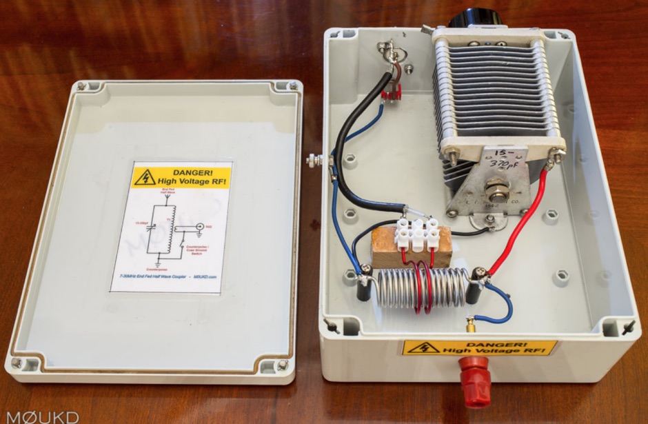 A home made end-fed half-wave antenna coupler with antenna lenght calculator and counterpoise calculator based on center frequency. Includes pictures and drawings along to antenna homebrewing instructions with a home made on air wound transformer
 -
 The Linked Dipole is a multiband antenna designed for 80/60/40/30/20m bands, optimized for the (tr)uSDX low bands configuration. It incorporates a 1:1 Balun to prevent common mode currents, ensuring balanced operation with coaxial cable. The Balun, wound on an FT140-43 core, achieves 37-40dB attenuation. The design includes a 3D-printable housing for compactness and waterproofing, with labeled link insulators for ease of use. Wire lengths were meticulously adjusted for optimal performance with a 7m pole and 3m rope extension, ensuring the antenna's ends are off the ground for improved behavior. The project includes downloadable printables for DIY construction.
 -
 This page describes a couple of parts box medicine bottle antennas that you can build. The ground side of the capacitor is soldered to the ground of the BNC connector. The positive side of the capacitor takes 5 turns around the toroid and is soldered back to itself. The center pin of the BNC connector takes 5 turns around the toroid and then continues on to the wire wound inductor. From there the antenna continues with an attached piece of wire.
 -
 I happened to stumble across some antenna projects showing common mode chokes 1:1 baluns made of some turns of coax wound on T200-2 iron powder toroids.
 -
 The _G3TSO_ Mobile Antenna Page details construction and tuning methods for mobile antennas operating across **10 to 160 metres**. The content describes a Hustler-based design, optimized for RF performance and vehicle speeds, featuring centre loading. For optimal operation on various bands, the loading coil placement requires clearance from the vehicle body. Antenna resonance is critical for efficient mobile operation. A mobile antenna's base impedance may be as low as 27 ohms, requiring specific matching to achieve maximum radiation, as a minimum SWR at the transmitter does not always indicate resonance or maximum output. Tuning involves physical adjustment of antenna length to achieve resonance at the operating frequency. The _G3TSO_ page outlines a tuning procedure utilizing a low-power signal source and a field strength meter to identify maximum radiation before impedance matching. Loading coil placement, either at the base, center, or top of the antenna, influences radiation efficiency and mechanical stability for mobile installations. Centre-loaded whips, such as the Hustler design, offer a compromise between efficiency and stability, often for single-band operation. Helically wound antennas, including those for **28 MHz**, may present base impedances around 17 ohms, resulting in a 3:1 SWR at resonance. Low resistance grounding at the antenna base is also specified for optimizing performance and minimizing RFI during mobile operation. DXZone Focus: Mobile | Any | Antenna Tuning | HF
 -
 There are quite a few recipes for building a suitable transformer for an end fed half wave antenna (EFHW), but I was never sure I really understood the main principles. So, I wound a bunch of transformers, made measurements on them using my NanoVNA, learned how to get what I really wanted out of the VNA measurements, and in the process discovered how to build better transformers and be able to predict what they will do
 -
 a 20M quarter-wave vertical antenna with a 6m telescopic mast, 1:1 balun, and spiral-wound driven element. Designed for QRP at 14.285 MHz, the antenna’s performance exceeded expectations, delivering low SWR and surprisingly quiet reception. Initial testing yielded successful contacts with European stations and EC1KR, showcasing its effectiveness. Compact and easy to deploy, the antenna promises to be an excellent portable solution for future hilltop operations.
 -
 The U01 emergency communications antenna is a versatile, multiband antenna designed for 80/60/40/20/17/15/10m bands, known for its reliability and compact size. It features a broadband transformer wound on various core options like FT82-43, FT114-43, or FT140-43, with the latter capable of handling up to 100W. The antenna incorporates a PCB with options for SMA and BNC connectors, and a weather-proofed design for durability. The lightweight construction, using materials like DX Wire UL and Polyester rope, makes it highly portable. The antenna's design has been tested and proven within the DARC Chapter U01, with multiple build options and detailed documentation available for DIY enthusiasts.
 -
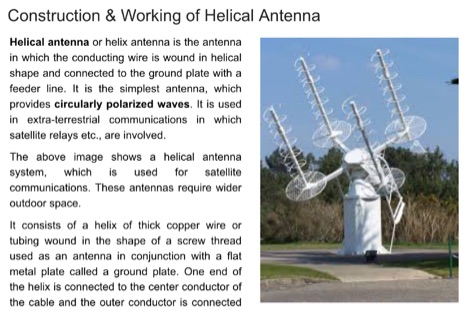 Helical antenna or helix antenna is the antenna in which the conducting wire is wound in helical shape and connected to the ground plate with a feeder line. It is the simplest antenna, which provides circularly polarized waves.
 -
 This article describes the construction of a simple dual-band VHF/UHF end-fed vertical dipole antenna designed for local repeater access using an Icom IC-705 radio. Built from a single piece of RG58U coaxial cable, the antenna consists of a 460mm exposed inner conductor, 450mm of intact coax, and a 9-turn choke balun wound on a 27mm former. Mounted on a 10m Spiderpole, the antenna achieves excellent SWR readings (<1.2:1 on 2m, <1.5:1 on 70cm) and provides effective coverage of local repeaters with unexpected reach into distant locations.
 -
 This comprehensive three-part guide examines baluns (balanced-to-unbalanced devices) and their critical role in ham radio antenna systems. The author explains how baluns prevent common-mode currents on feedlines, which can distort radiation patterns and cause unwanted RF in the shack. Various balun types are analyzed, including coiled coax chokes, ferrite-core designs (W2DU), and toroidal-wound versions (Guanella/Ruthroff). Construction techniques for 1:1, 4:1, 6:1, and 9:1 current baluns are provided with practical guidance on wire selection, winding methods, and ferrite core properties. The article emphasizes that proper balun implementation is essential for optimal antenna performance, especially with directional arrays.
 -
 Learn how an experienced ham radio operator rebuilt his trap dipole antenna for 30, 40, and 80 meters after a storm damage. Discover the process of upgrading to a short trap dipole for 40, 80, and 160 meters using double-wound traps made from RG-58 coax. Follow along for construction details and tips on building this unique classi.
 -
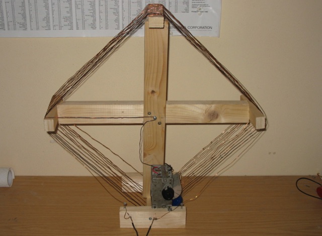 This loop antenna is intended to be connected as an antenna for receivers that do not have a built-in antenna such as an HF set or an old tube radio. This square barrel is wound on a wooden frame. It consists of two windings that are galvanically isolated from each other, a main and a coupling winding. The diameter is about 40 cm.
 -
 This resource details the construction and performance of a compact broadband magnetic loop antenna designed for portable receiving applications with devices like the _ATS MiniRadio_. The antenna utilizes approximately 3 meters of 0.5–1 mm copper wire wound in two turns on a rhomboidal wooden frame, measuring 50 cm by 70 cm. It connects via a modified 9:1 unun, where the primary center tap is isolated from ground to improve common-mode noise rejection. The design provides untuned operation across a frequency range from the longwave band up to approximately 25 MHz. Performance characteristics include observable directivity for noise suppression and the ability to connect directly to a radio or via a 50 coaxial cable for remote operation. The article specifies the unun's 3:1 turns ratio and its SMA output for connectivity. The methodology focuses on practical construction and observed reception quality.
 -
 Demonstrates the construction of an active loop converter specifically designed for the Low Frequency (LF) bands, addressing common localized noise interference in LF reception. The design integrates a sharply tuned circuit and a tuned loop antenna, utilizing the loop as the sole tuned inductive element. By applying positive feedback, the converter significantly increases the loop's effective Q, achieving factors between 1000 and 2000, which sharpens tuning and reduces noise. The circuit employs an _NE602_ mixer stage, feeding its output to an HF receiver, with a crystal-locked local oscillator at 4 MHz. A 20-turn, 0.8-meter square loop antenna with 500 uH inductance is detailed, connected via 2 meters of figure 8 flex cable. The converter offers three selectable frequency bands: 195-490 kHz, 150-220 kHz (including the New Zealand amateur band), and 128-160 kHz (covering the European amateur band). Performance measurements indicate an effective 3dB bandwidth of approximately 100 to 200 hertz at 200 kHz. The article provides insights into component selection, including an _LF353_ op-amp and a trifilar wound transformer on a ferrite core. Sensitivity figures are presented, showing 7.5 uV of converted output per 1 uV/meter signal strength into a 50-ohm load, or 37.5 uV into an _FRG7_ receiver, highlighting its capability to extract weak signals from noise.