Search results
Query: yagi antennas 9 element
Links: 59 | Categories: 1
Categories
-
 This resource provides comprehensive instructions for constructing a 2 element quad antenna specifically designed for the 10, 12, and 15 meter bands. The antenna features a diamond configuration, which offers improved gain compared to a square configuration. The author shares insights into the materials used, including a square-aluminum boom and bamboo poles, along with construction techniques that ensure durability and optimal performance. This project is ideal for amateur radio enthusiasts looking to create their own antennas at home. In addition to construction details, the author discusses the antenna's performance, noting its effectiveness even at a height of 8 meters. The quad antenna reportedly performs comparably to a 3 element yagi, with excellent SWR readings and strong signal reports from European stations. This project is suitable for beginners and offers a cost-effective solution for those interested in enhancing their amateur radio setup with a homemade antenna.
 -
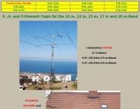
 2-Element parasitic Yagis for the Shortwave-Bands 10-12-15-17-20-30m. The antennas are feeded with the DK7ZB-match. A quarter-wave choke of coax is grounded at the socket.
 -
 4 Element Cubical Quad, Yagis, LZA Circular Quad, Shrunken Quad , quarter wave, J-Pole, beam mounting , changing polarity
 -
 Build a portable VHF yagi antenna for 2 meters. All you need is two rabbit ear antennas from Radio Shack, two CATV baluns, four feet of 3/4 CPVC pipe with one tee.
 -
-
 A JavaScript to calculate the dimensions for a seven element Yagi-Uda Antenna
 -
 Details the construction and optimization of antenna systems for amateur radio satellite operations, focusing on practical, homebrew solutions for VHF/UHF bands. It covers building _groundplane antennas_ from salvaged materials, recycling old beam antennas into new configurations like a 2-meter crossed yagi, and constructing a 10-meter horizontal delta loop. The resource also explains antenna matching techniques, including folded dipole driven elements and quarter-wave transformers, along with the importance of accurate SWR measurements and minimizing coax loss. Demonstrates how to achieve a **1:1 SWR** by carefully trimming elements and adjusting radial angles on groundplane antennas. It provides insights into selecting appropriate coax and connectors, highlighting the benefits of Belden 9913 for low loss and the proper installation of _N-connectors_. The article also addresses RFI mitigation from computer birdies and presents a design for a silent triac antenna control circuit, offering practical solutions for common satellite station challenges.
 -
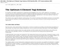
 The **NW3Z** optimized wideband antenna designs, originally presented at Dayton 2001, detail Yagi configurations for the 20-meter, 15-meter, and 10-meter amateur radio bands. This resource provides access to the design files, likely containing critical parameters such as element spacing, element lengths, and boom dimensions, which are essential for replicating these directional antennas. The designs focus on achieving wide bandwidth, a desirable characteristic for contesters and DXers operating across a significant portion of each band. The content specifically references "nw3z-Antenna-DesignsDownload," indicating that the core information is available as a downloadable file, presumably in a format suitable for antenna modeling software or direct construction. Such files typically include **NEC models** or similar data, allowing for performance analysis and optimization before physical construction. The emphasis on "optimized wideband" suggests design considerations for SWR bandwidth and gain characteristics over a broader frequency range than typical narrow-band Yagis. The resource serves as a direct source for specific, proven antenna designs from a known amateur radio antenna designer, offering practical data for hams interested in building high-performance Yagi arrays for HF.
 -
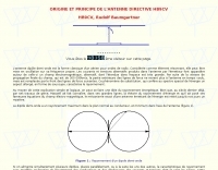 Basics and principles of the HB9CV antenna by Rudolf Baumgartner. This antenna join electric advantages of the two elements direct feeded aerials with the mechanical advantages of the Yagi antennas, in French.
 -
-
 The BV6 50 MHz Yagis resource details the construction of two distinct Yagi antenna designs for the 6-meter band, specifically a 1-wavelength (1wl) model and a 2.1-wavelength (2.1wl) model. The 1wl Yagi, with a boom length of 5.850m, achieves a gain of **9.4 dBd**, while the 2.1wl Yagi, spanning 12.90m, boasts a gain of **11.9 dBd**. These designs adhere to a proven methodology for optimizing current slope and maintaining constant phase delay across parasitic elements, ensuring high gain per boom length and an _excellent pattern_. Both designs target a 50-ohm input impedance, facilitating straightforward feeding with a robust folded dipole. Final verification using NEC-II software confirmed the antennas' exceptional stacking capabilities, yielding stacking gains exceeding **5.8 dB** for a 2x2 array with minimal mutual detuning. The resource provides common mechanical data, including boom and element diameters, and specifies element lengths corrected for boom diameter. While the original _DUBUS Technik V_ publication contained incorrect element lengths, this resource provides the accurate dimensions for proper construction, emphasizing the use of readily available materials for cost-effective amateur radio deployment.
 -
 Simple gain antennas for the beginner, a 2 element HF yagi antenna
 -
 VE7CA reprint an interesting article taken from arrl antenna compendium. Two elegant practical and portable 6-meter gain antennas, a two-element quad and a tree-element Yagi antenna for 50 Mhz-6 meter band
 -
 Includes EH antennas, 7Mhz vertical monopoles, 5 elements vee log-yagi for 10m and more
 -
 ON6MU Optimized 10 and 6 and 4 element UHF Yagi Antenna
 -

-
-
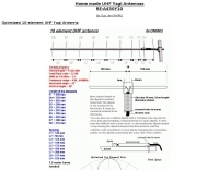
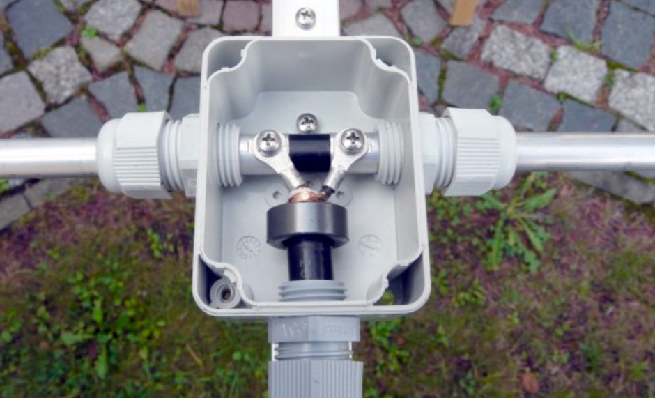
 Demonstrates the design and construction of a 9-element Yagi antenna for the **70 cm band** (432 MHz), based on the DK7ZB concept. The resource details EZNEC+ calculations for a single antenna, providing gain, sidelobe suppression, and front-to-back ratio figures. It also presents a comprehensive analysis of stacking two such antennas, including optimal stacking distance (1000 mm) and the resulting performance enhancements for the stacked array, such as an increased gain of 17.03 dBi. The article includes detailed drawings, wire file dimensions in millimeters, and azimuth/elevation plots for both single and stacked configurations. Practical construction steps are documented with original photographs, illustrating element mounting, the **28 Ohm matching system** using two quarter-wave 75 Ohm transmission lines, and the critical N-connector wiring. It also covers the iterative process of fine-tuning the driven element length to achieve a return loss of 20 dB, validating the EZNEC+ simulation results with actual measurements.
 -
 Demonstrates the product line of _LZ Antenna Ltd._, a Bulgarian manufacturer specializing in amateur radio antennas and custom electronic devices. The company focuses on robust, high-quality HF multiband Yagi and vertical antennas, leveraging over 20 years of experience from founder Georgi Georgiev in radio amateur development. Featured models include the LZA 8-4, LZA-10-3, and the LZA-7-3A WRTC 2022, alongside various rotary dipoles like the LZA1 40/30m. Provides specifications for several Yagi antennas, such as the LZA-9-5, LZA-13-7, and LZA-6-3 (a 6-element, 3-band design). The company emphasizes applying "leading edge technology" to high-frequency communication equipment production, with products designed for durability and performance. The LZA-10-5 Yagi offers **12.5 dBi** gain on 10m, while the LZA-13-7 provides **13.2 dBi** on 20m, showcasing competitive gain figures for DXing and contesting.
 -
 Collection of different techniques to homebrew PVC yagi antennas, including elements assembling, baluns and chokes, radiator box tips and tricks by dk7zb
 -

-
 A 70cm and 2m 6 elements yagi antenna plan based on the IEEE Transactions on Antennas and Propagation
 -
 A 4 element addition for 10m to an existing 4 element yagi (ZX antennas)
 -
 The antenna is a VHF side is a 2m moxon, tuned on 145.825 MHz. The driven element of the moxon couples to a driven element for a 5 element 70cms Yagi, tuned on 436.5 MHz.
 -
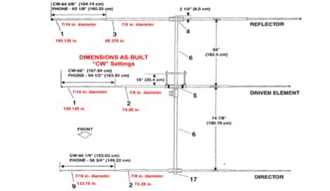
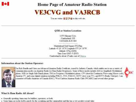 VE3CVG 222 MHz (1.25m) 6 element plumber's delight yagi antenna
 -
 The design and feeding of driven elements for VHF/UHF Yagi antennas , modeling, observations and some case studies by Graham Daubney F/G8MBI
 -
 Ground Plane - 1/4 wave vertical, J-Pole, 3 Element Yagi Beam and simple antenna supports
 -
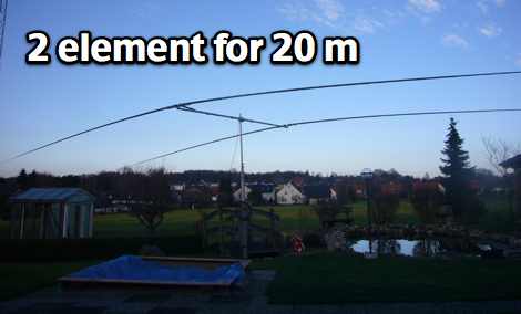
 Based on a simple project based on a 2 elements Yagi for 20m band, and then becomed a triband yagi with a open-sleeve feed system
 -
 The HyGain LJ-153BA a monoband 3 element Yagi, designed for the 15 m band 21.00 - 21.45 MHz
 -
 50 MHz extended 6-7 element ZX-Yagi antenna. Dimensions for the 7 elements and information on performance of a 2 stacked antennas featuring a total max gain of 20.8 dBi
 -
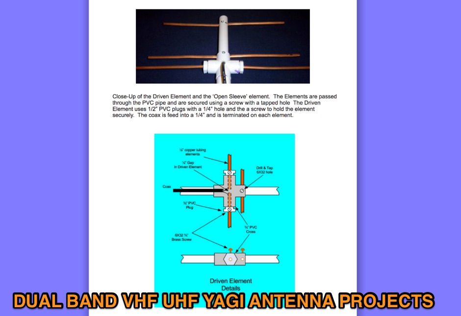 On this page are designs for Dual Band 2M / 70cm antennas. All antennas are 50 ohm designed driver. These Yagis have a unique element called a Open Sleeve. 4 Element 5 element and 9 element Dual Band - 2M / 70cm antenna projects
 -
 This antenna was designed for the CQ WW CW 2009 at EA8URL. All elements are made out of fishing rods with an insulated copper cable fixed on the rods by cable ties. Both fishing rods and cable are UV resistant.
 -
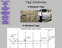
 A presentation of the Yagi Antennas, and other interesting tid-bits by Brian Mileshosky. The document provides an in-depth exploration of the Yagi-Uda antenna, detailing its historical development, design principles, and performance characteristics. Originally described in the 1920s, the Yagi antenna features a driven element and parasitic elements, including reflectors and directors, which collectively determine its behavior. The document highlights how element lengths, diameters, and spacing influence gain, impedance, and directivity. It also discusses the antenna's reciprocal nature and presents data on typical gain values for various element configurations. Additionally, the text covers practical considerations, such as the construction of a "Tape Measure Yagi" for amateur use, and touches on related antenna types like dipoles and their application in Near Vertical Incident Skywave (NVIS) communication.
 -
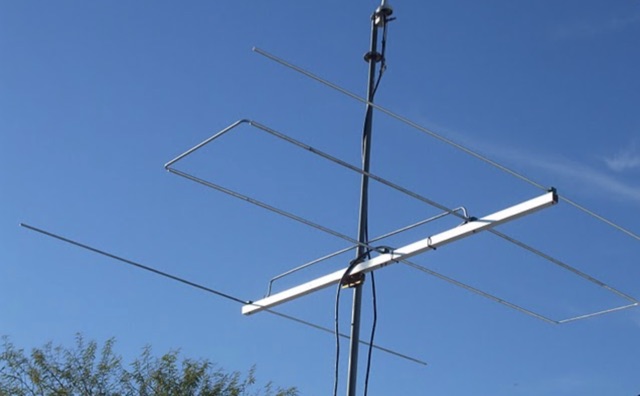
 Constructing a compact directional antenna for the 17-meter band, this resource details the build process for a Moxon rectangle, a two-element Yagi variant with folded-back elements. It covers the antenna's evolution from the _VK2ABQ beam_ and provides specific dimensions for a version built using fishing pole whips. The content includes a discussion of the antenna's radiation pattern, feedpoint impedance, and its inherent front-to-back ratio, which is often superior to a standard two-element Yagi. Practical considerations for element spacing and material choices are also addressed, alongside a visual representation of the antenna's physical layout. Performance data presented includes a comparison showing the Moxon rectangle's **2.5 dB gain** over a half-wave dipole and a front-to-back ratio of **20 dB**. The resource also touches upon the antenna's relatively wide bandwidth for a two-element beam and its suitability for portable operations due to its compact footprint. It offers insights into optimizing the design for specific operating conditions and discusses the advantages of its lower take-off angle compared to omnidirectional wire antennas, making it effective for DX contacts on the 17-meter band.
 -
 Three Yagi antennas for the six meters band by 9A7PJT. Include a 4 element yagi, a custom design 4 element, and a 5 element yagi with antennas pictures and design.
 -
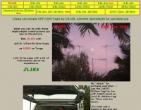
 A 7 dB directional gain is reported for this portable VHF Yagi antenna design, which utilizes cut metal tape measure sections for its elements. The resource details the construction process for a 2-meter band antenna, emphasizing its ease of build and portability. It specifically mentions the design's suitability for radio direction finding (RDF), fox hunting, and communication with satellites and the International Space Station (ISS), highlighting its practical applications for amateur radio operators. The construction cost is estimated at under $20, with potential for even lower expense if salvaged materials like old tape measures and PVC pipes are used. The article references _Joe Leggio's_ (WB2HOL) original design, noting specific alterations made by the author. It also compares this design to other DIY Yagi antennas, including _FN64's_ 2-meter band and _manuka's_ 70-cm band tape measure Yagis, underscoring its unique combination of simplicity, portability, and effective performance with a 1:1 SWR achievable on the 2-meter band.
 -
 Pictures, design plan and description of a 5 element yagi antenna for the 4 meters band by 9A7PJT
 -
 A great and efficient monoband VHF portable antenna. The article consist of two version of a 12.5 Ohm 3 elements yagi beam antenna plans for the two meter band, a full sized and a shortened version expecially designed for the SSB and CW on 144 MHz.
 -
 Presents _Beam Quest_, the official Japanese distributor for _SteppIR_ antennas, detailing their product lineup and services. The site showcases various _SteppIR_ Yagi models, including the _Dream Beam_ series (DB42, DB36, DB18E, DB11) with configurations from two to four elements, alongside the _Big IR_ and _Small IR_ vertical antennas. It also lists accessories such as TX/RX and PC interfaces, essential for integrating these advanced antenna systems into a ham shack. Operators often seek out _SteppIR_ antennas for their dynamically adjustable element lengths, which allow for optimization across multiple bands, a significant advantage for DXing and contesting. This adaptability contrasts sharply with fixed-element Yagis, providing a distinct edge in varying band conditions. The resource provides contact information, including email and phone numbers, for inquiries and support regarding _SteppIR_ products within Japan, serving as a direct point of contact for sales and technical assistance.
 -
 A practical guide on hombrewing Yagi antennas, including notes on Driven Element, Transformation & Symmetrising Coax Lines, Full Boom length vs. electrical length, Elements & Insulators on Boom and additional tips and tricks, in English and German
 -
 The calculator designs the Yagi-Uda antenna based on the DL6WU model with boom correction, following the G3SEK-DL6WU method. It optimizes the antenna for maximum gain and allows adjustment of passive elements without affecting SWR. DL6WU antennas are known for their high gain, minimal sensitivity to nearby objects, and stable performance in various weather conditions.
 -
 Antennas for the 1296 MHz based on the construction plans of some Yagis 35 elements by DL6WU, F9FT, DJ9YW. These antennas features a boom of about 3 m and gives a gain of about 17.8 dBd
 -
 A short 3 element LFA Yagi for 50MHz with a 1.94M boom. This antenna has been designed in order to minimise the upward and downward lobes typically seen the the EL plane on Yagi antennas.
 -
 10 Elements Cross-Yagi Antenna for 433 MHz. The base of the 10el antenna is the recalculated RA6FOO antenna.Circular polarization is realized - by a phasing quarter-wave line, matching of horizontal and vertical polarization antennas
 -
 German antenna parts dealer, provides antenna element holders, element clamps for yagi antennas, junction boxes, aluminium plates and rods. Offers also Rope tensioners, plugs and adapters and any additional part you need when you want to make your own antenna.
 -
 A hexagonal beam is a form of the Yagi antenna which is based on parasitic principles developed early in the last century in Japan for achieving gain in one direction.How HexBeam antennas works. A hexagonal beam operates exactly like Yagi antenna, but instead of a driven element that is straight like a dipole, it is a wire bent into the shape of the letter M.
 -
 Learn about the practical design and construction of Yagi antennas for ham radio operators. This post explores the benefits of Yagi antennas in receiving and transmitting RF signals, concentrating signal energy in one direction for long-distance communication. Discover the theory behind Yagi antennae, the importance of element size and spacing, and the resources available for sizing and construction. Whether you're interested in OTA television or amateur radio communication, understanding Yagi antenna design can enhance your signal reception and transmission capabilities.
 -
 In this article the author describes his personal experience on some antennas for 50 MHz he tested on the field, the six meter Dipole, Vertical, Moxon, a 3 element Yagi and an Omniangle antenna.
 -
 This DIY guide details constructing a 5-element Yagi antenna for VHF frequencies. Yagi antennas offer directional signal transmission/reception compared to omnidirectional ones. The guide covers material selection (aluminum, screws, etc.), design using software or formulas, and step-by-step assembly including cutting elements, drilling holes, and attaching the coaxial cable. While calculations are provided for a 146 MHz design, adjustments are necessary for different frequencies. Safety precautions and potential result variations are emphasized.
 -
 Learn how to build wire Yagi antennas for your ham radio setup. Discover how smaller wire elements can offer practical and portable options for temporary operations. Explore designs like the Hex Beam, Spider Beam, and Moxon that require less mechanical complexity and can be easily rotated or supported. Find out how to construct and hang wire Yagis from ropes, trees, or masts with inverted vees or horizontal elements. Get tips on element positioning, gain, and beamwidth considerations. Follow simple construction steps using a rope boom and marking element positions for efficient assembly. Enhance your ham radio experience with versatile wire Yagi antennas.