Search results
Query: 7 MHz band
Links: 589 | Categories: 11
Categories
- Operating Modes > 70 MHz
- DX Resources > Beacons > 10 meter beacons
- Antennas > 20M
- Antennas > 23cm
- Antennas > 2M
- Antennas > 30M
- Antennas > 40M > 40 meter Dipole Antennas
- Antennas > 40M > 40 meter Yagi Antennas
- Antennas > 4M
- Antennas > 6M > 6 meter Moxon Antennas
- Radio Equipment > HF Vertical Antenna > Maldol MFB-300
-
 Understanding radio wave propagation is fundamental for effective HF communication, and this guide from the Galway Radio Club elucidates the principles behind _Near Vertical Incidence Skywave_ (NVIS) operation. It begins by contrasting NVIS with line-of-sight and surface wave propagation, highlighting its utility for reliable regional coverage, particularly in challenging terrains or within the skip zone. The document explains how NVIS leverages high-angle radiation, refracting signals from the ionosphere to return to Earth within a circular region, typically up to **650 km** (400 miles) from the transmitter. The guide delves into critical factors influencing NVIS, such as the _critical frequency_ (Fo) and the Maximum Usable Frequency (MUF), emphasizing their dependence on solar activity, time of day, and season. It provides practical advice on frequency selection, noting that 40 meters is often the highest daytime NVIS band, with 60 meters and 80 meters favored as darkness falls. The author, EI5DD, suggests using an ionogram for real-time propagation data, considering it more reliable than generic ham-clocks. Antenna considerations are also covered, recommending dipoles, inverted vees, or phased dipoles positioned 0.1 to 0.25 wavelengths above ground for optimal high-angle radiation. The document mentions mobile NVIS setups, including military configurations and commercial options like the Barrett Communications roof-rack antenna, which can cost around **£2000.00**. It concludes by reinforcing NVIS as an essential technique for national emergency communications, with 5 MHz (60m) and 80 meters being primary bands for daytime and nighttime operations, respectively.
 -
 Effective suppression of harmonics and parasitic radiation from HF transmitters is crucial, especially with the increasing sensitivity of VHF/UHF radio channels to interference. This project details a hybrid low-pass filter (LPF) designed to operate across the HF bands up to 51 MHz, making it suitable for 6-meter band operations while providing deep VHF/UHF suppression. The design addresses the challenge of modern interference landscapes, where even microvolt-level signals can disrupt wireless sensors and other simple VHF/UHF receivers. The filter utilizes a single elliptic link, combining high cutoff steepness with robust suppression in the hundreds of megahertz range. A key feature is the use of only two standard capacitor values, simplifying construction and component sourcing. The article provides a detailed schematic, performance characteristics, and _RFSim99_ model file, demonstrating a reflection coefficient S11 below 0.017 (VSWR < 1.03) across 1-51 MHz, ensuring minimal degradation to the antenna system. Construction notes include coil winding specifications and capacitor selection guidance, with recommendations for _FR-4_ assembly. Two capacitor sets are presented, with the first variant recommended for its lower RF current demands, keeping currents below 3 A at 1 kW passing power at 51 MHz. Fine-tuning involves adjusting frameless coils, with considerations for capacitor tolerance and high-frequency capacitance measurement accuracy.
 -
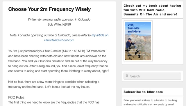 When new to the 2-meter FM transceiver, securing a quiet frequency for chatter seems straightforward, but it's essential to navigate FCC rules and band plans effectively. Even though frequency allocations are consistent above 50 MHz for Technician licenses, adherence to specific segments within the 2m band—ranging from 144 MHz to 148 MHz—is crucial. This includes respecting designations for different modes like CW, SSB, and FM to prevent interference, particularly with satellites and exotic modes like EME. Understanding and following the structured band plans not only ensures legal compliance but also optimizes frequency use and minimizes disruptions in the amateur radio community.
 -
 This project involved designing a 7-pole Chebychev broadcast band filter to address severe interference issues caused by a new horizontal loop antenna on the KN-Q7A transceiver. The interference overwhelmed the transceiver’s front end, so a custom filter with a 3.5 MHz cutoff was built using silver mica capacitors and type 6 T130 toroidal cores. Encased in a diecast box with SO239 sockets, the filter blocks strong signals from the broadcast band, achieving over 100 dB attenuation. Tested up to 100W, it reduces interference effectively while maintaining low insertion loss across HF bands.
 -
 145 MHz is the target frequency for this 2-meter Skeleton Slot Yagi Stack antenna project. The design focuses on feeding two stacked Yagi antennas using a skeleton slot radiator, which is a unique approach for VHF enthusiasts. The project details the construction process, including the loop tapered matching section for impedance matching, ensuring optimal performance. The use of specific components like the EH789 element holder and MB456 main mast bracket is highlighted, providing clarity on the assembly process. The construction utilizes 20x20 box aluminum bar for durability and precision. Key dimensions, such as the element length (ER-ED4) and main boom spacing (MM123), are meticulously outlined. This attention to detail aids in replicating the antenna design accurately. The downloadable PDF offers comprehensive instructions, making it accessible for amateur radio operators interested in VHF antenna construction. This project is particularly beneficial for those looking to optimize their 2-meter band operations. The inclusion of a skeleton slot radiator and loop tapered matching section demonstrates advanced techniques in antenna design, catering to both intermediate and advanced builders.
 -
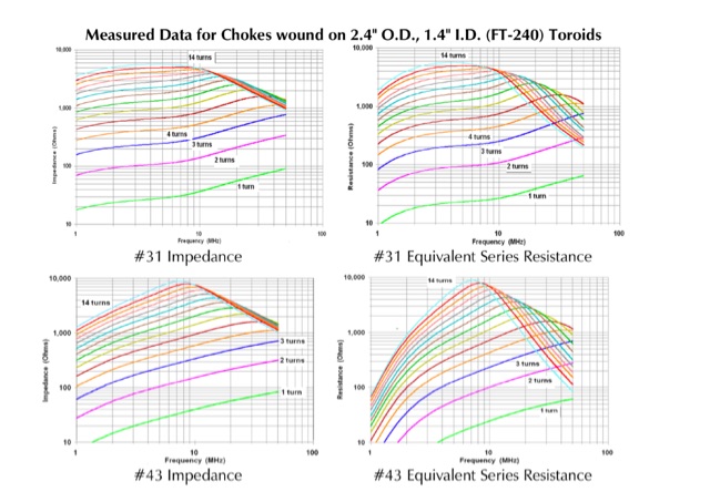 FT-240 toroids measurements. The data was measured using well-calibrated HP instrumentation. All plots have been adjusted to a frequency range of 1-100 MHz on the horizontal axis and a resistance/impedance range of 10-1,000 ohms on the vertical axis. This adjustment facilitates comparison among different materials and aids in determining their suitability for use on the HF ham bands.
 -
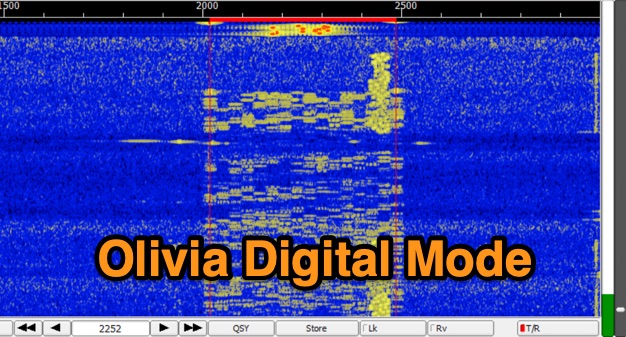 The Olivia digital mode, a **Multi-Frequency Shift Keying (MFSK)** radioteletype protocol, is specifically engineered for robust communication under difficult propagation conditions on shortwave radio bands from 3 MHz to 30 MHz. Developed by Pawel Jalocha in 2003, Olivia signals can be decoded even when the noise amplitude exceeds the digital signal by over ten times, making it highly effective for transmitting ASCII characters across noisy channels with significant fading and propagation phasing. Early on-the-air tests by Fred OH/DK4ZC and Les VK2DSG on the Europe-Australia 20-meter path demonstrated intercontinental contacts with as little as one-watt RF power under favorable conditions. Common Olivia modes are designated as X/Y, where X represents the number of tones and Y is the bandwidth in Hertz, with examples including 8/250, 16/500, and 32/1000. The resource clarifies that Olivia, unlike some other digital modes, produces a constant envelope, allowing RF power amplifiers to achieve greater conversion efficiencies and making it less prone to non-linearity. Operators are advised that **Automatic Level Control (ALC)** can be set higher than no meter movement for MFSK modulation, as long as it's not driven past its high limit, contrary to common misinformation about other digital modes. The Olivia community encourages voluntary channelization on suggested calling frequencies, such as 14.0725 MHz for 8/250, to facilitate initial contacts, especially for signals below the noise floor. The Olivia Digital DXers Club provides links to Groups.io, Facebook, and Discord for community engagement and offers details on QSO parties.
 -
 An FT-817 ceased transmission on the VHF 2m band, despite the other HF, UHF, and 50 MHz bands operating correctly. Suspecting an excess of input signal during FT-8 mode transmission, they conducted measurements with an oscilloscope, revealing a burnt-out PIN diode, identified as D3003, type HSU277, on the PA unit board. Following the replacement of this surface-mounted diode, their FT-817 resumed operation on the 144 MHz band.
 -
 Demonstrates the construction of an active loop converter specifically designed for the Low Frequency (LF) bands, addressing common localized noise interference in LF reception. The design integrates a sharply tuned circuit and a tuned loop antenna, utilizing the loop as the sole tuned inductive element. By applying positive feedback, the converter significantly increases the loop's effective Q, achieving factors between 1000 and 2000, which sharpens tuning and reduces noise. The circuit employs an _NE602_ mixer stage, feeding its output to an HF receiver, with a crystal-locked local oscillator at 4 MHz. A 20-turn, 0.8-meter square loop antenna with 500 uH inductance is detailed, connected via 2 meters of figure 8 flex cable. The converter offers three selectable frequency bands: 195-490 kHz, 150-220 kHz (including the New Zealand amateur band), and 128-160 kHz (covering the European amateur band). Performance measurements indicate an effective 3dB bandwidth of approximately 100 to 200 hertz at 200 kHz. The article provides insights into component selection, including an _LF353_ op-amp and a trifilar wound transformer on a ferrite core. Sensitivity figures are presented, showing 7.5 uV of converted output per 1 uV/meter signal strength into a 50-ohm load, or 37.5 uV into an _FRG7_ receiver, highlighting its capability to extract weak signals from noise.
 -
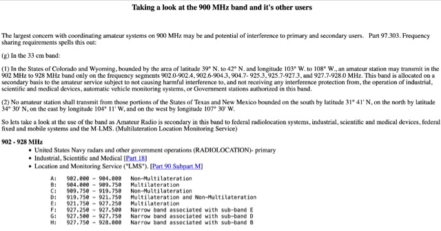 Use of the band as Amateur Radio is secondary in this band to federal radiolocation systems, industrial, scientific and medical devices, federal fixed and mobile systems and the M-LMS. Bandplans for hams. Allocation in 902 - 928 MHz
 -
 The RXC70/10 is a sensitive 70 MHz to 10-meterband converter using the Philips SA602 mixer IC. It operates with high stability and low noise, converting 70–72 MHz signals to 28–30 MHz for general coverage receivers. The compact, low-power design (15mA) supports various modulations and uses. Its versatility makes it suitable for amateur radio applications with proper tuning and antenna setup.
 -
 The Central States VHF Society, Inc. (CSVHFS) is a not-for-profit organization chartered in the state of Missouri. It was begun in the mid-1960s to foster amateur radio operation on the bands above 50 MHz.
 -
 Presents the design and construction of a folding 5-element Yagi antenna specifically engineered for 144 MHz portable operation, particularly for VHF contest Rover categories. It details element dimensions, boom construction using ¾-inch pine, and a folding mechanism that reduces the 52-inch boom to 26 inches for transport. The document provides a table with precise element distances and lengths, including a 2.4 mm length correction for solid parasitic elements, and specifies the use of 3/16-inch solid aluminum for parasitic elements and brass tubing for the driven element. It also covers the bent dipole driven element design for impedance matching, balun implementation with Type 31 ferrite beads for common mode current suppression, and weatherproofing for the feed point. The resource includes predicted performance data from 4NEC2 modeling, showing SWR and return loss characteristics, as well as gain and front-to-back ratios at various frequencies across the 2-meter band. It reports a measured SWR of 1.2:1 at 144.2 MHz and 1.5:1 at 147 MHz, corrected for 25 feet of RG-8/M coaxial cable loss. The design offers approximately 1.5 dB more gain than a previous 4-element design, maintaining a decent SWR up to 147 MHz, and was successfully deployed in a winning June 2016 ARRL VHF Contest Rover entry.
 -
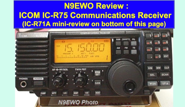 Icom IC-R75 tabletop HF communications receiver came onto the market back in 1999 and was taken out of production in late 2015. Frequency coverage is from 30 hz right to 60 MHz. This allows one to catch the 6 Meter amateur band as well.
 -
 A versatile digital VFO design utilizing the Silicon Labs Si5351a oscillator chip and Nokia 5110/3310 graphics LCD display, operating from 1-160MHz with dual VFO capability. This microcontroller-based system, powered by an ATmega328 processor, features rotary encoder tuning, selectable step sizes, RIT control, and comprehensive band memory functions. Drawing less than 40mA at 3.3V, it significantly improves upon previous DDS designs' power consumption while offering advanced features like S-meter display, VFO lock, and programmable BFO/CIO offsets. The design achieves flexible functionality through simple hardware implementation and efficient software architecture, making it particularly suitable for QRP and portable amateur radio applications.
 -
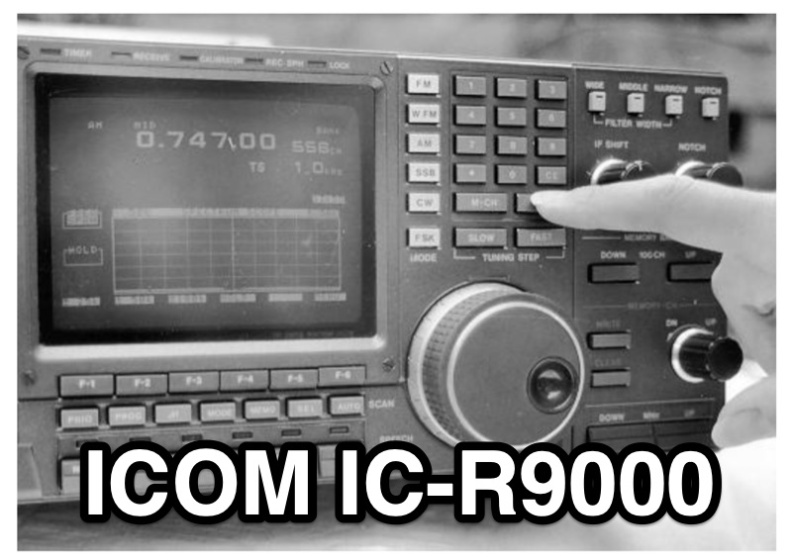 Assessing the ICOM IC-R9000 communications receiver, this review details its operational parameters and user experience for radio enthusiasts. Introduced in 1985, the IC-R9000 covers a broad frequency spectrum from 0.1 MHz to 1999.8 MHz, making it suitable for a wide array of listening activities from medium wave (MW) to VHF/UHF. Key performance metrics include a dynamic range of **102 dB** with the narrow SSB filter, crucial for discerning weak signals in crowded bands, and its substantial physical dimensions of 424 x 150 x 365 mm and 20 kg weight. The receiver's architecture supports various modes, though it notably lacks synchronous detection, a feature often desired for improved AM reception under fading conditions. It incorporates 1000 memory channels and robust scanning capabilities, facilitating efficient monitoring across its extensive frequency range. This analysis provides insights into the IC-R9000's capabilities and limitations, offering a historical perspective on a significant piece of amateur radio and shortwave listening hardware.
 -
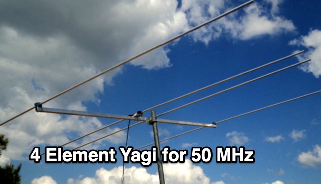 Guide to constructing an effective antenna for 50MHz. Inspired by a design from Martin DK7ZB, the article emphasizes the importance of precise measurements and quality materials. With a 2.20m boom and careful assembly, the antenna promises excellent performance, resilience, and cost-effectiveness, making it ideal for six meter band operations.
 -
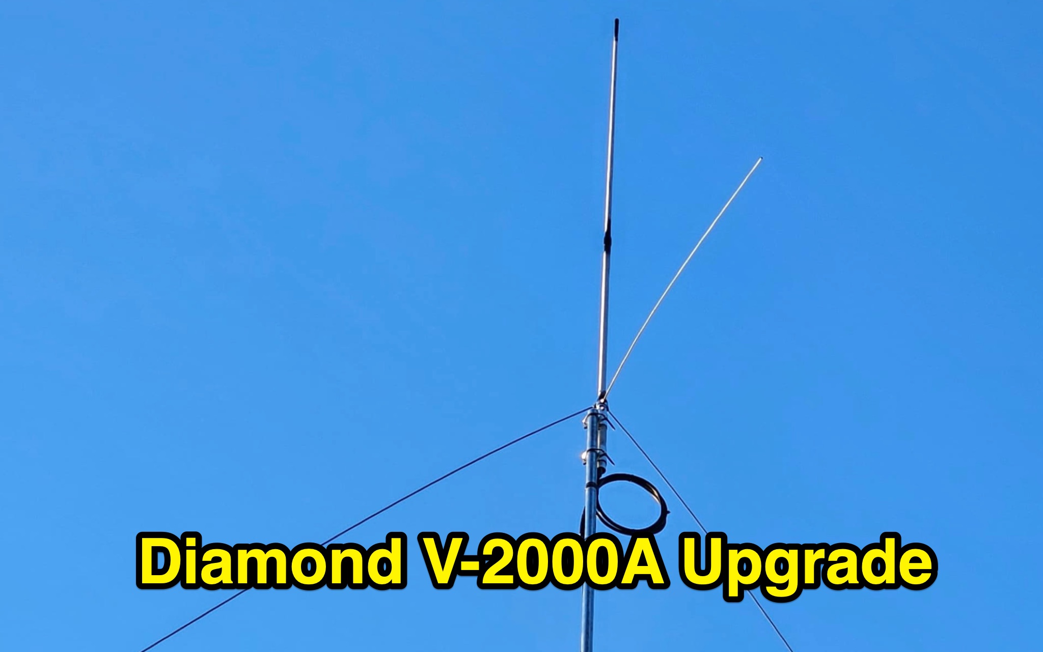 Learn how to enhance the performance of your Diamond V2000A antenna by optimizing the length of the radials. Discover a cost-effective method to create improved radials using simple materials like aluminum tubes and bolts. Explore the benefits of this modification for 6m band, unlocking triband capabilities and better SWR. Find out how a ham radio operator from Europe successfully upgraded their V2000 antenna and achieved impressive results. Save money by DIY-ing your radial enhancements instead of purchasing expensive replacements.
 -
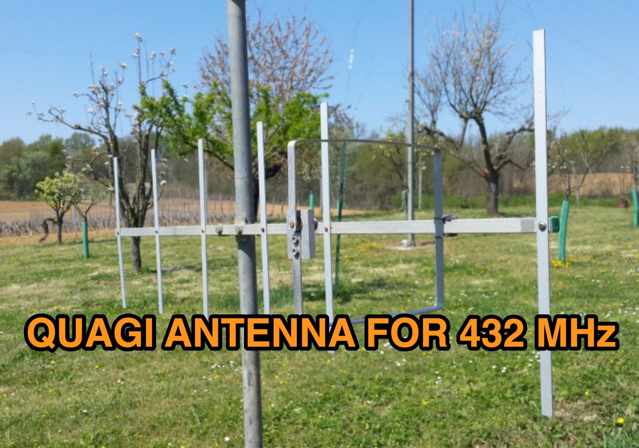 Antenna project for a home made quagi antenna for UHF Bands, 432 MHz. This projects is done using some aluminium bar rods and includes design and pictures of the project
 -
 This project documents the construction of a coaxial 50 MHz notch filter to eliminate inter-band interference between 50 and 70 MHz transceivers. Using RG-213 coax and based on quarter-wave stubs, the filter achieved a 44 dB attenuation at 50.060 MHz while maintaining low insertion loss on 70 MHz. A dual-stub design broadened the notch response and minimized attenuation on 70 MHz to 0.2 dB. Fine-tuned using an FA-NWT network tester and Elecraft XG3 signal source, the filter effectively resolved interference for seamless dual-band operation.
 -
 The Zeppelin antenna, a J-type design, is presented as a two-band HF dipole, offering independent operation on harmonically related frequencies. This resource details its electrical configuration, comprising a half-wave radiator end-fed by a quarter-wave matching section, and explores its historical evolution from early Zeppelin airship applications to modern amateur radio use. The article specifically examines how a Zepp antenna tuned to 28.4 MHz (10 meters) exhibits a harmonic relationship with 15.4 MHz (20 meters), noting a frequency ratio of approximately 1.84:1, which deviates from a perfect 2:1 due to factors like elevation, wire separation, velocity factor, and end-effect. Antenna modeling results, including SWR sweeps at 28.4 MHz (1.1 SWR) and 15.4 MHz (1.6 SWR), are provided through Graph 1 and Graph 2, illustrating the antenna's performance across these bands. Current distribution patterns for both the 28.4 MHz (second harmonic) and 15.4 MHz (first harmonic) operations are visually represented in Figure 2 and Figure 3, respectively. The author also includes a 4NEC2 model's "Symbol Conversion file" definitions and calculated #14 wire dimensions for achieving resonance at 28.4 MHz, with the antenna positioned at a height of 33 feet. The discussion further highlights the antenna's versatility, suggesting its potential as a single-band, center-fed, 15.4 MHz half-wave folded end dipole when fed at a specific low current point. This analysis provides practical insights into constructing and optimizing a multi-band Zepp antenna for HF operations, emphasizing its unique harmonic characteristics and physical compactness.
 -
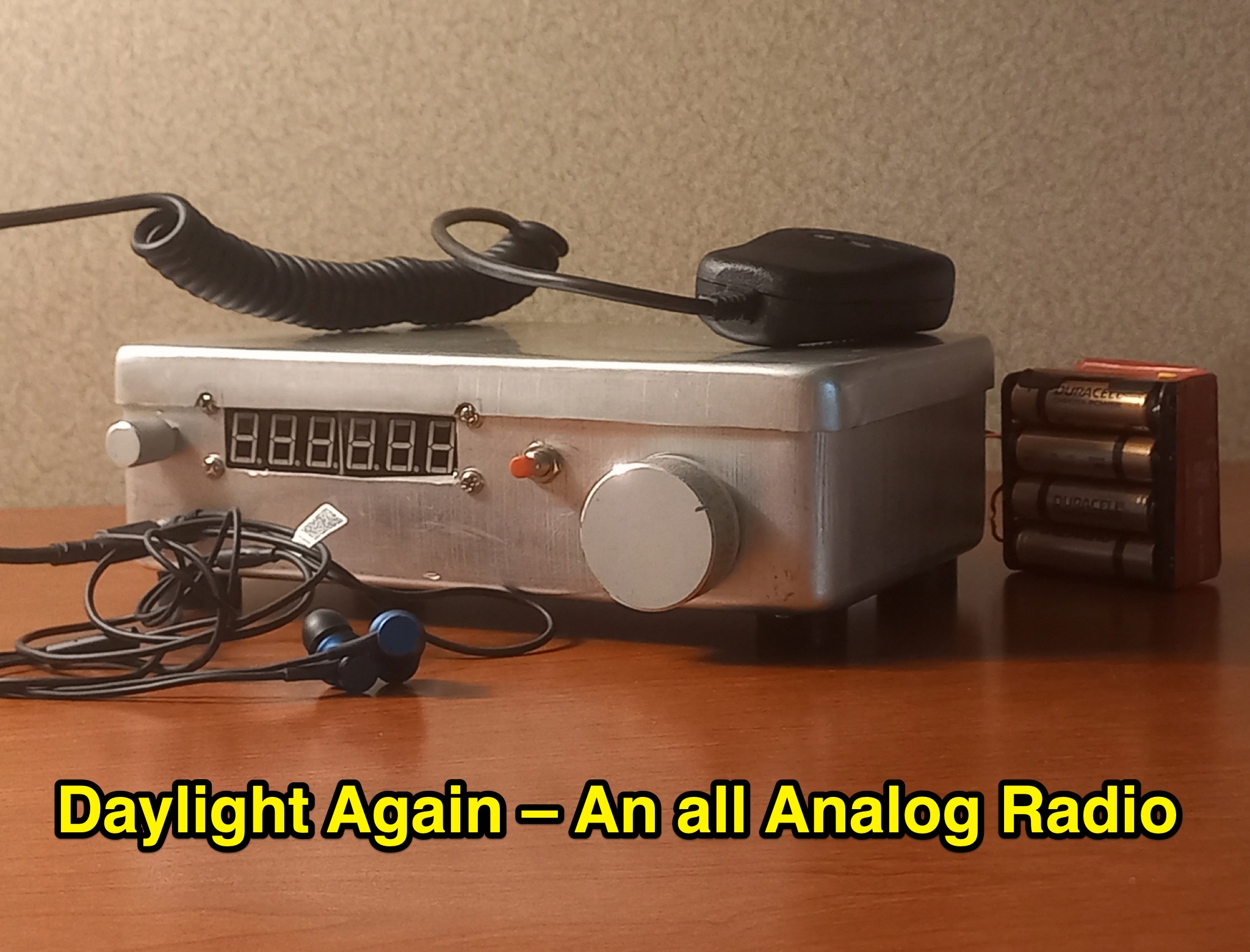 This article discusses a high performance, 7MHz, 5 watt SSB rig, the Daylight Radio, an all-analog radio design from the 1980s that includes a full circuit diagram, IMD NR60 calculations, QER crystal filter, bandpass filter, receiver portion, and more. The author explores the design, components, and functionality of this analog radio for hams interested in vintage or homebrew radio projects.
 -
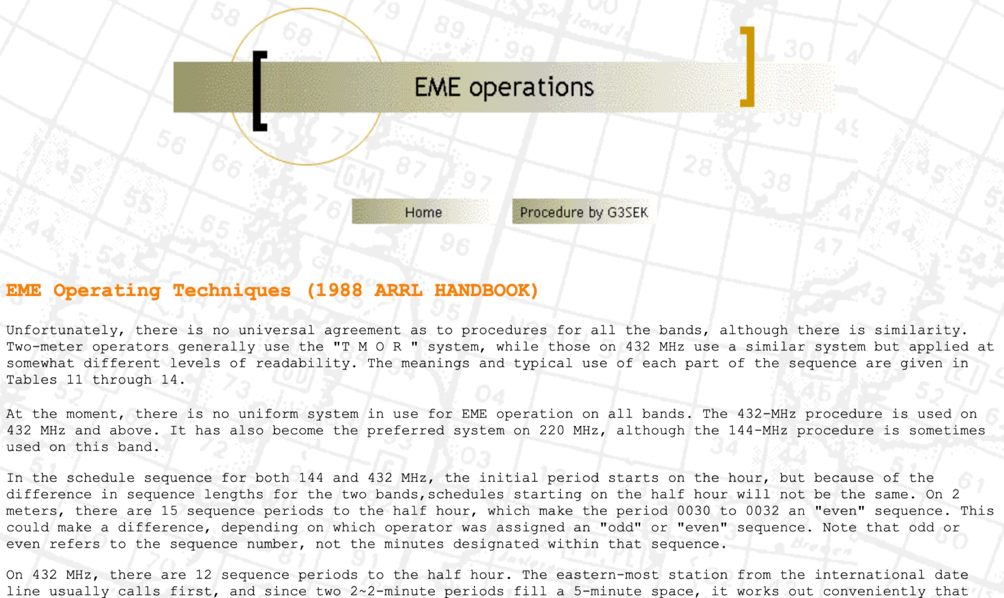 This resource provides an in-depth look at Earth-Moon-Earth (EME) operating techniques specifically for the 432 MHz band and above. It outlines the differences in operational procedures between the 144 MHz and 432 MHz bands, emphasizing the importance of sequence lengths and scheduling. The initial calling period typically starts on the hour, with the eastern-most station calling first, which is crucial for effective communication. The document also discusses the challenges faced by operators, such as signal readability and the necessity of confirming exchanges. It highlights the significance of using a standardized procedure to enhance the likelihood of successful contacts. Additionally, it covers the use of signal reports and the importance of patience and clarity in communication, especially when dealing with weak signals. Overall, this guide serves as a valuable resource for amateur radio operators interested in improving their EME operations.
 -
 This article describes the implementation and testing of a low-power GPS tracker using LoRa technology in the 433MHz amateur band. The system, built with AIThinker RA-02 modules and Arduino controllers, demonstrated successful communication over non-line-of-sight distances up to 5km. Operating with a 125kHz bandwidth and spreading factor of 11, the tracker achieves a data rate of 500 bits/sec. Powered by a LiPo cell with power-saving features, the final compact design operates for approximately 1.5 weeks between charges with 3-minute reporting intervals, consuming just over 1mA in idle mode.
 -
 The ICOM IC-R75, introduced in 1999, operates on 13.6 Volts DC and measures 241 by 94 by 229 mm. Its coverage spans from 30 kHz to 60 MHz, making it a versatile receiver for various bands. The review details available accessories, including optional filters and the **UT-106 DSP module**, which significantly enhances signal processing capabilities. Performance comparisons are drawn against other notable receivers such as the Drake R8B and earlier ICOM models, providing context for its audio quality and overall functionality. User feedback is integrated, offering practical insights into its daily operation and reception characteristics across the spectrum. This analysis offers an in-depth look at the IC-R75's technical capabilities and features, serving as a valuable reference for operators interested in this **legacy receiver**.
 -
 The article discusses the construction of a UHF band-stop stub filter to protect an APRS receiver from potential damage during a balloon launch. The author, who communicates using a 441 MHz transmitter, needed to ensure that the RTL-SDR dongle receiving at 144 MHz wouldn't be damaged by the transmissions. The solution involved creating a quarter-wavelength open stub filter using coaxial cable, which attenuates the 441 MHz signal while allowing the 144 MHz signal to pass through. The filter's design is based on the principles of constructive and destructive interference, with careful measurement and trimming to achieve the desired frequency response. The final filter provided 34.8 dB of insertion loss at 441 MHz and minimal loss at 144 MHz, effectively protecting the receiver.
 -
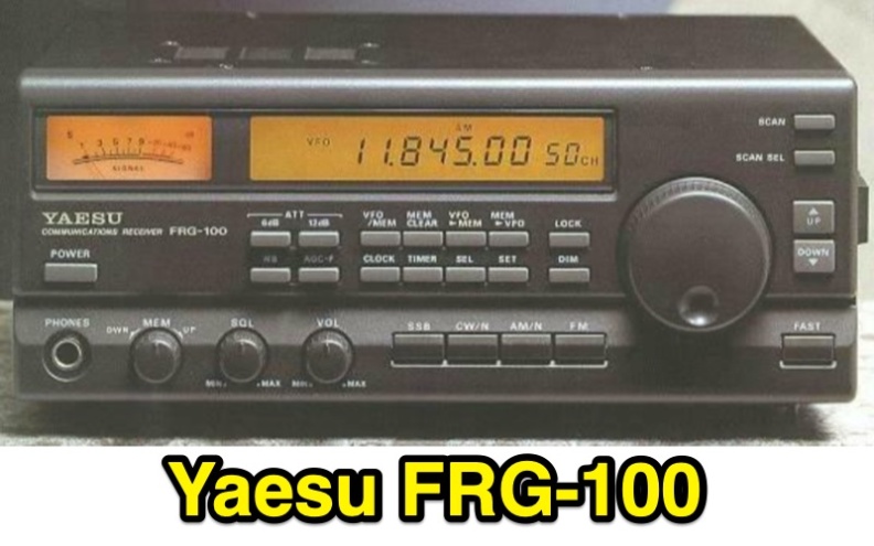 The **Yaesu FRG-100** shortwave receiver, introduced in 1992, operates across a frequency range of 50 kHz to 30 MHz, accommodating AM, LSB, USB, and CW modes, with an optional narrow-band FM capability. Its physical dimensions are 238 x 93 x 243 mm, with a weight of 3 kg, making it suitable for both portable and fixed station deployments. Power options include standard mains voltage or 12VDC, providing operational flexibility for diverse listening environments. The front panel integrates a manual tuning knob, an analogue signal strength meter, and an LCD display that provides critical information such as frequency, operating mode, memory channel, and time. Users can configure various operational parameters, including tuning steps and bandwidth filters, to optimize reception for specific signals. This review highlights the FRG-100's straightforward interface and its utility for shortwave listening enthusiasts. The design emphasizes user-friendly adjustments for settings, which contributes to its appeal among those interested in general coverage reception.
 -
 The author discusses ways to display VHF and higher bands using a K3/10 as transverter, NooElec Upconverter, SDR, and SDR-Console. He observed that the results were remarkable, with the tuned frequency visible at +/-100kHz. The K3 Interface Option (KXV3A) produces a buffered IF output at 8.213MHz, which is received using a NooElec NESDR SMArt SDR dongle and Ham It UP Upconverter. The SDR-Console program is utilized, with Omnirig synchronizing the SDR and K3. To configure the system, particular parameters are required, such as adjusting the IF frequency to 133.213MHz (125MHz + IF frequency) and inverting the spectrum. The Panadapter demonstrated ES activity at 10m, and modest software tweaks may be required for improved performance.
 -
 The 4m Slim Jim antenna project provides a construction guide for a low-cost, high-performance aerial designed specifically for the 70 MHz FM band. This design achieves a 1:1 SWR across the 4m FM band with straightforward adjustment of the feed point, utilizing RG-58 coax. Its low angle of radiation contributes to effective signal propagation. Construction involves using plastic knitting needles as spreaders and a telescopic fishing pole for support, with components secured using two-part epoxy. Annealed bare single-core copper wire forms the radiating element. The setup process includes raising the antenna at least 3 meters above ground for tuning, adjusting the RG-58 feed point for optimal SWR, and then soldering connections. Waterproofing is achieved with yacht varnish. The design emphasizes low wind resistance for durability, making it suitable for exposed outdoor installations. A PDF construction diagram is available to supplement the written instructions.
 -
 SAT filters ensure effective full-duplex satellite QSOs by mitigating interference between 145 MHz uplink and 435 MHz downlink signals. Custom coaxial and SMD-based filters address transmitter harmonic interference and improve receiver isolation, achieving over 70 dB suppression in the undesired band. Designed for simplicity, these filters maintain optimal VSWR and are housed in shielded brass enclosures. Practical implementations with Yagi antennas demonstrate compatibility with SDR systems, enabling seamless communication even in challenging satellite conditions, such as low-elevation passes and DX pile-ups.
 -
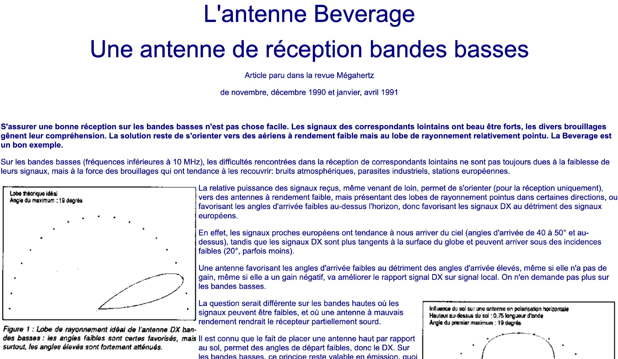 This article discusses the Beverage antenna, a reception antenna for low bands, originally published in the Megahertz magazine between November 1990 and April 1991. It explains the challenges faced in receiving signals on low bands due to interference and how the Beverage antenna's directional radiation pattern can help improve reception of distant stations. The article highlights the importance of choosing antennas with low efficiency but sharp radiation lobes for better DX signal reception. It also compares the reception characteristics of signals from European stations versus DX stations, emphasizing the benefits of antennas favoring low arrival angles for DX signals on low bands.
 -
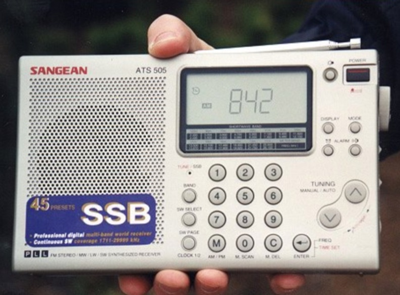 Examines the Sangean ATS-505 portable receiver, a unit introduced in March 2000, providing an in-depth analysis of its capabilities. The review details critical specifications such as its 6 Volt DC power requirement, utilizing 4 AA batteries, and its physical dimensions of 128 x 214 x 39 mm, weighing 840 g without power cells. Frequency coverage spans **LW** from 153-279 kHz, **MW** from 520-1710 kHz, **SW** from 1711-29999 kHz, and FM from 87.5-108 MHz, making it a versatile listener for various broadcast types. Key features highlighted include a backlit display for low-light operation, 45 memory presets for quick access to favorite stations, and the inclusion of Single Sideband (SSB) mode, which is crucial for serious shortwave listening and utility monitoring. The review also draws technical comparisons with other Sangean models, specifically the ATS-404 and ATS-909, pointing out differences in band coverage and operational features. This independent assessment offers practical insights into the ATS-505's performance, helping enthusiasts understand its place within the portable receiver market.
 -
 Learn about Amateur Television (ATV) on the 23 cm band (1240-1300 MHz) in this article from the September and October 2000 issue of Mégahertz magazine. Discover how ATV adds a new dimension to QSOs by allowing hams to visit stations, transmit real reports on antenna installations, follow signal paths on camera, and have simultaneous sound transmission. Explore the world of ATV experimentation, comparison, and innovation, made easier by existing equipment in many ham radio operators' homes. Find out about the ATV bands, bandwidth requirements, and the 23 cm band as a starting point for ATV activities.
 -
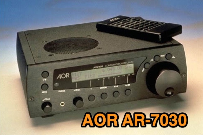 Examines the AOR AR-7030 communications receiver, detailing its technical specifications and operational characteristics. The resource describes its compact design, CNC machined aluminum cabinet, and a frequency range spanning 0-32 MHz. Key features include a ceramic metal cased 4 kHz AM filter, with typical bandwidths of 2.2 kHz, 4.0 kHz, 5.3 kHz, and 9.5 kHz, alongside 400 memory channels and multi-timer functionality. It emphasizes the receiver's high-quality components and a design philosophy focused on reliable performance without superfluous features, making it a dedicated tool for serious listeners. The review assesses the AR-7030's performance within its price class, particularly for **medium wave** and **shortwave** reception. It provides insights into how the receiver's design choices, such as its robust construction and specific filter options, translate into practical listening experiences. The analysis highlights its suitability for users prioritizing signal clarity and operational stability over extensive, complex features, offering a clear perspective on its utility for dedicated DXers and broadcast listeners.
 -
 Home page of CE3SAD with information on his activity and progress expecially on the six meters band with audio recordings of some 50 MHz QSOs.
 -
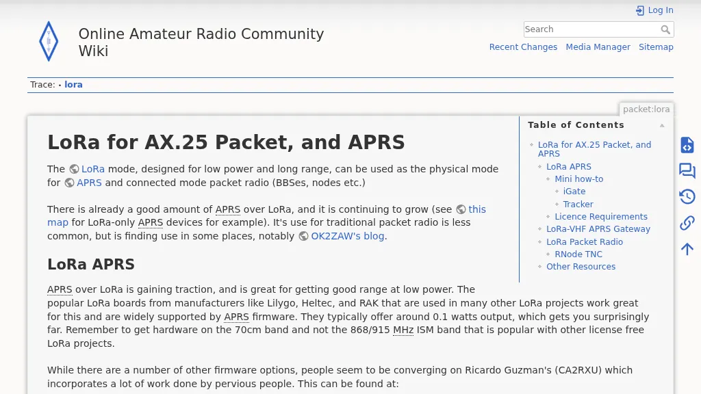 The resource details the use of LoRa for AX.25 packet radio and APRS, focusing on practical implementation. It specifies UK LoRa APRS frequency and modulation settings: **439.9125 MHz**, 125kHz bandwidth, SF12, and CR 4/5. The content provides a mini how-to for setting up an iGate using VS Code and _Platformio IDE_, with specific instructions for a Lilygo LoRa32 V2.1_1.6 board, including configuration for Wi-Fi, beaconing, and APRS-IS passcode. It also covers tracker setup using a Lilygo T-Beam Supreme, detailing firmware flashing and configuration for mobile operation. The guide differentiates LoRa APRS from traditional connected-mode packet radio, explaining why common LoRa APRS firmware is unsuitable for full AX.25 packet due to its TNC2-style payload structure. It explores alternative solutions for true LoRa packet radio, such as using an _RNode_ TNC or Raspberry Pi LoRa TNCs, and provides commands for RNode firmware installation and configuration for serial KISS operation. The resource also touches upon licensing requirements for unattended Digipeaters in the UK, noting the need for ETCC coordination and MB7Uxx callsigns.
 -
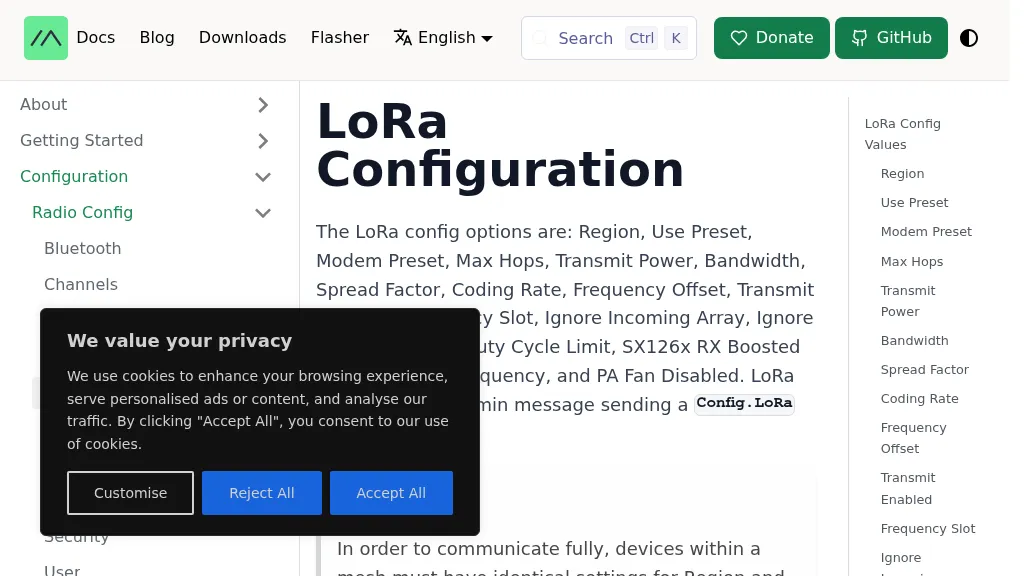 The Meshtastic documentation outlines critical LoRa configuration parameters for node operation, emphasizing regulatory compliance. It details settings such as Region, Modem Preset, Max Hops, Transmit Power, Bandwidth, Spread Factor, Coding Rate, and Frequency Offset. A comprehensive table provides region codes, frequency ranges (e.g., US **902.0 - 928.0 MHz**), duty cycles, and power limits (e.g., EU_433 **12 dBm**) for numerous countries, including the US, EU, China, and Japan, alongside a 2.4 GHz band option. It explicitly states that devices within a mesh must share identical _Region_ and _Modem Preset_ settings for full communication. Modem Presets, like _LONG_FAST_ (the default), optimize for either speed or range, directly impacting network congestion and message delivery delay. For instance, SHORT_TURBO offers the fastest speed and shortest range, while VERY_LONG_SLOW provides the longest range but is less reliable for mesh formation. The document also highlights specific duty cycle limitations, such as the 10% hourly limit for EU_433 and EU_868 regions, and provides command-line interface (CLI) examples for configuring these parameters.
 -
 For amateur radio operators seeking resilient, off-grid communication, the _MeshCom_ firmware provides a robust solution for text-based messaging over a mesh network. Utilizing LoRa modulation and the APRS protocol, this firmware is designed for low-energy consumption and cost-effective hardware, primarily operating in the 70cm band. Nodes, identified by amateur radio callsigns, can send short text messages to all participants or directly to specific callsigns, functioning as repeaters to extend network reach. The system supports automatic status and position messages, with optional sensor data for WX-Data and Telemetry. MeshCom nodes can be configured as gateways to HAMNET or the internet, enhancing connectivity options. The project emphasizes a self-building and self-healing mesh network architecture, crucial for emergency communication scenarios. Operating frequencies include **433.175 MHz** (EU, USA, Africa), 439.9125 MHz (UK), and 433.925 MHz (Norway). The firmware is compatible with hardware platforms such as ESP32/LoRa modules, RAK-WISBLOCK, and ESP32-DEV4/E22-LoRa, offering a flexible deployment for various amateur radio applications.
 -
 Presents the NED International DX Group, a **CB radio** organization established in the Netherlands on August 23, 2026, by 19NED000 and 19NED001 Henricus. The group primarily operates on the **11-meter band**, utilizing various modes including FM, AM, LSB, USB, CW, FT8, FT4, FT2 Ross, and JS8, with all digital modes permitted. Membership is free and open to active operators and SWLs. Key operating frequencies include 27.405 LSB, 27.265 USB for FT8, and 27.245 USB for JS8. The group also maintains activity on PMR Channel 10 at 446.11875 MHz FM. The organization is actively seeking volunteers for roles such as webmaster (proficient in PHP, MySQL, and security), digital eQSL and paper QSL card management, logo and banner design, and country/province directors.