Search results
Query: 1 GHz
Links: 138 | Categories: 4
-
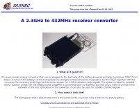 Receiver converter that can be plugged to the backside of the Yaesu FT-817 battery powered portable transceiver
 -
-
 Establishing a robust, interconnected communication infrastructure across challenging terrain, the Island Trunk System (ITS) provides a network of open amateur radio repeaters for general and emergency communications throughout Vancouver Island, surrounding waters, and parts of the lower mainland on the West Coast of British Columbia, Canada. This system, largely off-grid, relies on solar power and batteries, necessitating careful operation, especially during night hours and low solar charging seasons, to preserve its energy resources. Maintaining the ITS involves significant effort from many hams, who appreciate adherence to regulations, including proper station identification. The system hosts a weekly social net every Monday evening at 8 PM, welcoming all participants, and also supports a Vancouver Island Region Emergency Radio Net each Wednesday at 19:15. Experimental projects like the Newcastle Ridge webcams, linked via 5.8 GHz broadband backhaul over 206 km to Nanaimo and Comox, demonstrate the innovative spirit within the ITS community. A new VHF repeater, operating on 146.880 MHz with a 141.3 Hz PL tone, was installed in Tofino, expanding system coverage.
 -
 Triple-band (2-2.5 GHz, 6.5-7 GHz, 12-13 GHz) central receive systems with automatic airborne tracking.
 -
 When building antennas for the Wifi band , a need for an easy way to check the antennas arise. This is a project for a 2.4 GHz band SWR Meter
 -
 A fractional bandwidth of up to 30:1 characterizes spiral antennas, making them highly effective across a very wide frequency range, often from 1 GHz to 30 GHz. The resource details two primary types: the **Log-Periodic Spiral Antenna** and the **Archimedean Spiral Antenna**, defining each with specific polar functions and illustrating their planar configurations. It explains that spiral antennas are typically circularly polarized, with a Half-Power Beamwidth (HPBW) of approximately 70-90 degrees, and a peak radiation direction perpendicular to the spiral plane. The content elaborates on critical design parameters affecting radiation, including the total length (outer radius) for lowest frequency, the flare rate ('a' constant) for optimal radiation versus capacitive behavior, the feed structure (often an infinite balun) for high-frequency operation, and the number of turns (typically 1.5 to 3 turns). It also discusses the theoretical impedance of 188 Ohms for Log-Periodic spirals, derived from Babinet's Principle, noting actual impedances are often 100-150 Ohms. The article presents a simple construction method for an Archimedean spiral, demonstrating VSWR and efficiency measurements. Measurements from a constructed spiral antenna show a VSWR that is fairly constant across the band, albeit with a mismatch loss of about 3 dB. The antenna efficiency remains around -5 dB (31.6%) across its operating range, indicating a decent wideband radiator despite opportunities for optimization.
 -
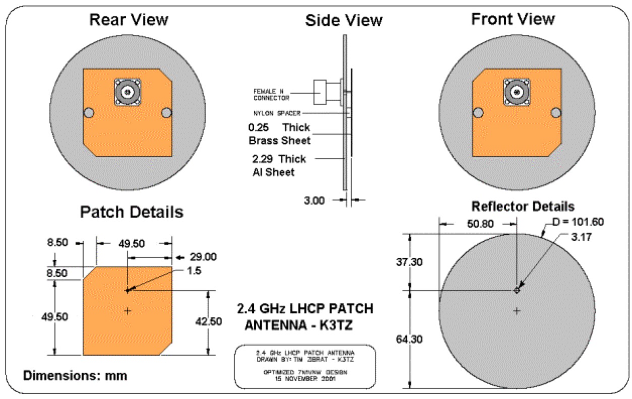 Using patch antenna for amateur radio reception of the 13cm band with a sample 2.4 GHz LHCP patch antenna by K3TZ
 -
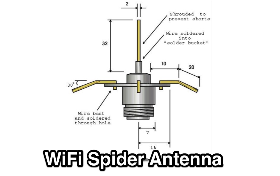 Quarter wave omni-directional spider antenna for 2.4GHz 802.11b
 -
 A home made project, scan and monitor the 2.4 GHz band using a common MMDS downconverter.
 -
 Protecting amateur radio equipment from transient overvoltages requires robust lightning and surge protection, which is the focus of Electronic Specialty Products. The company provides various devices, including coaxial lightning arrestors for antenna feedlines and surge protectors for AC power lines and data circuits. These devices are engineered to divert high-energy surges, such as those caused by direct or indirect lightning strikes, away from sensitive transceivers, amplifiers, and computer components, thereby preventing catastrophic damage. Key products include the _Coaxial Lightning Protector_ series, designed for various impedance levels and frequency ranges up to 3 GHz, and the _AC Line Surge Protector_ for shack power distribution. Effective deployment of these protection devices can significantly reduce the risk of equipment failure and ensure operational continuity during severe weather. For instance, a properly installed coaxial arrestor can handle peak currents of **20 kA**, while AC line protectors offer clamping voltages typically below 400V. Comparing different models reveals varying levels of insertion loss and return loss, with some coaxial units exhibiting less than 0.1 dB loss at 500 MHz, making them suitable for high-performance HF and VHF/UHF operations. Integrating these components into a comprehensive grounding system is crucial for achieving maximum protection against both common-mode and differential-mode surges.
 -
 Over 100 amateur radio beacon audio files are presented, offering a direct auditory experience of propagation conditions across a wide spectrum of frequencies, from 1.8 MHz to 47 GHz. These recordings, primarily captured by IW3FZQ and IK3NWX, document signals from beacons such as DK0WCY, IY4M, GB3RAL, and S55ZRS, providing a valuable resource for **propagation study** and **beacon monitoring**. Each entry in the list specifies the beacon's callsign, its operating frequency in kHz, and the recording operator. This compilation includes signals from beacons located in various grid squares like JN55VF, JO44VQ, and IO91IN, illustrating diverse geographical origins. The frequencies covered span the 160m, 80m, 40m, 30m, 20m, 17m, 15m, 12m, 10m, 6m, 4m, 2m, 70cm, 23cm, 6cm, 3cm, 1.2cm, and 6mm amateur bands. Users can listen to these recordings to identify characteristic beacon tones and observe signal strength variations. The resource also invites other radio amateurs to contribute their own beacon audio files, fostering a collaborative archive of propagation data. The last update to this collection was on March 24, 2009, indicating a historical snapshot of beacon activity. Accessing the files requires the Real Player software.
 -
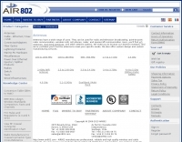
 Benelec Pty Ltd specializes in the design and manufacturing of **antennas** and RF components, covering a broad frequency range from 0.002 GHz to 8 GHz. Their product line includes Land Mobile Radio Antennas, such as HF 2-30MHz, VHF 40-180MHz, and UHF 200-520MHz models, alongside specialized Military Antennas for dismounted, UxS, C2, and EW applications. The company also produces Cellular Antennas, including 4G/5G and GPS/GNSS types, and Marine Antennas for both vessel-mounted and fixed-site installations. Additionally, Benelec offers a comprehensive range of coaxial cables, connectors like N-Type and SMA, and various radio accessories. The company's offerings extend to RF components such as duplexers, diplexers, and 50 Ohm loads, as well as DAS components like directional couplers and hybrid combiners. Benelec provides EMP and lightning protection solutions, including 1/4 Wave Stub protectors and replaceable GAS capsules. Their product catalog also features P25, DMR, and FM Analog radios, along with portable and mobile radio accessories like batteries, chargers, and cabled headsets. The company supports various sectors with robust communication solutions.
 -
-
 A cheap rf signal generator for 2.4 GHz
 -
 W1GHZ Palm Software, special-purpose contest logging program for the ARRL 10GHz Cumulative Contest.
 -
 ITELITE manufactures omnidirectional, sector and directional antennas 900 MHz 2.4 GHz 3.5 GHz 5 GHz 5.8 GHz antennas.
 -
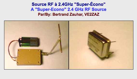
 Pictures and description of a homemade 1.3 GHz and 2.4 GHz RF Signal Source
 -
 Manufacture of microwave directional, omni directional, sector and multisector antennas with horizontal polarization for ISM band 2,4 GHz
 -
 Valcom Guelph specializes in the design and manufacturing of a full range of MF Beacon 100 KHz - 600 KHz, AM Broadcasting 540 - 1700 KHz, HF 1.8 - 30 MHz, VHF 30 - 300 MHz and UHF 300 - 1,200 MHz and SHF up to 6 GHz antennas based in Canada
 -
-
 Manufacturer of WiFi (2.4 & 5 GHz), Marine WiFi, Military and other antennas of various frequencies and styles.
 -
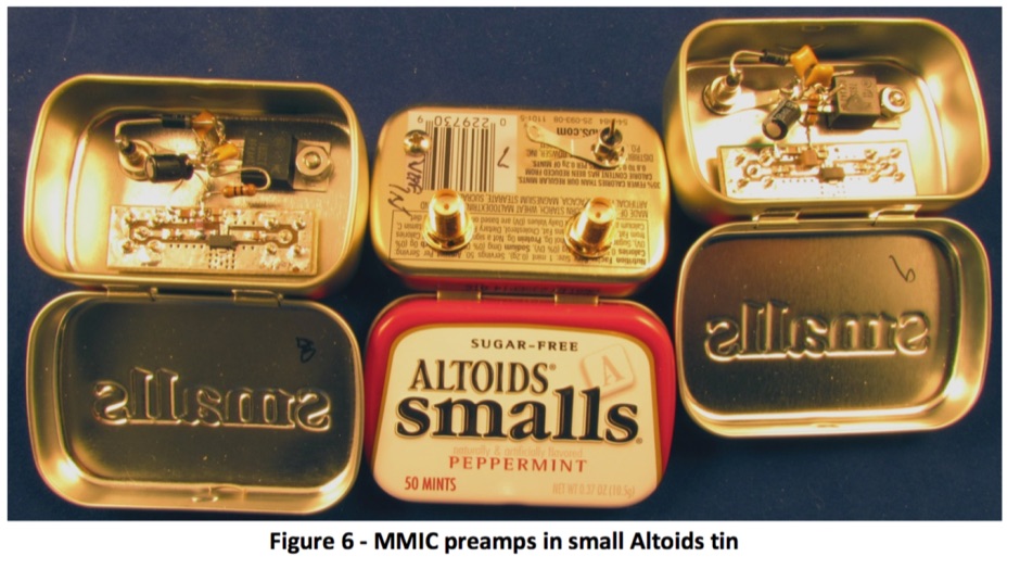 Who needs a GaAsFET? Tuning, constructions and Packaging by Paul Wade
 -
 Home page of PA3BTL with information on Linux, packet radio, sattellite keppler data links, Proxim RangeLAN2 2.4 GHz radio's, Lucent WaveLAN 2.4 GHz radio's and link to LXE homepage
 -
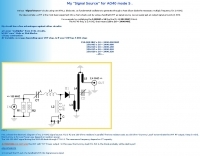 Signal source circuit for 2.4 GHz by sv1bsx
 -
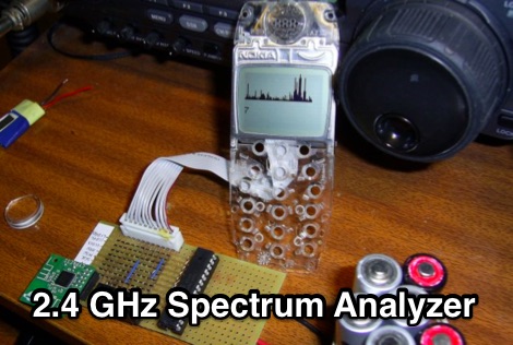 A spectrum analyzer based on ATMega8 microcontroller and a CYWM6935 within a Nokia mobile phone case.
 -
 Operates fast-scan FM-television in the 1.3, 2.3 and 10.3 GHz bands
 -
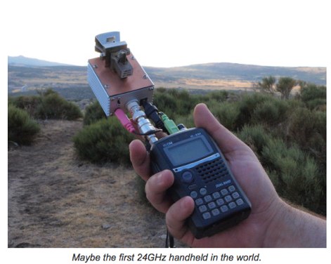 Using old FM microwave equipment to operate the amateur radio 24 GHz band by EA4EOZ
 -
 This site is dedicated to design and analysis of micro- and millimeter wave filters from 0.5 to above 100 GHz.
 -

-
 The resource provides coaxial cable attenuation data, listing signal loss in dB per 100 feet for various cable types across a frequency range from 1 MHz to 5.8 GHz. The initial table details attenuation for cables such as _RG-58_, _RG-8X_, and RG-213, with impedance values of 50 ohm or 75 ohm, at frequencies up to 1 GHz. For example, _RG-58_ exhibits **0.4 dB** loss at 1 MHz and **21.5 dB** loss at 1 GHz per 100 feet. A subsequent table expands on this data, including LMR series cables like _LMR-400_ and LMR-600, along with other types such as 9913F7 and RG214. This section covers frequencies from 30 MHz to 1,500 MHz, also noting the outer diameter of each cable. For instance, _LMR-400_ (0.405" diameter) shows **0.7 dB** loss at 30 MHz and 5.1 dB loss at 1,500 MHz per 100 feet. The final section focuses on VHF/UHF/Microwave amateur and ISM bands, presenting attenuation in dB per 100 feet (and meters) for frequencies including 144 MHz, 450 MHz, and 2.4 GHz. This table includes larger diameter hardline options like 1/2" LDF and 7/8" LDF, in addition to flexible coaxial cables. For example, 1/2" LDF cable demonstrates **0.85 dB** loss at 144 MHz and 6.6 dB loss at 2.4 GHz per 100 feet. DXZone Focus: Coaxial cable attenuation | LMR-400 | RG-58 | 5.8 GHz
 -
 The SETI League, Inc., founded in 1994, focused on participatory science, developing technology to seek definitive answers to the question of extraterrestrial intelligence. The organization operated in five dozen countries across all seven continents, maintaining the quest for cosmic companions through the efforts of its 1500 members. Although the organization shuttered its virtual doors after thirty years in 2024, the website remains for educational and historical purposes, documenting past research and activities. Key technical resources include the _SETI League Mini-Manual_ for constructing a 12 GHz radio telescope under $200, and software like _SETIFox for Windows_ and _Radio Eyes_ for radio astronomy sky viewing. The site also features _Project Argus_ detections, moonbounce signal detections, and space probe signal detections, providing concrete examples of amateur radio astronomy applications. Publications such as the quarterly newsletter _SearchLites_ and various articles by Dr. SETI (H. Paul Shuch, Ph.D.) are available, alongside information on the Third Penn State SETI Symposium in 2025. The site also offers insights into hydrogen line emission observations, presented in time domain, frequency domain, waterfall, and surface plot formats.
 -
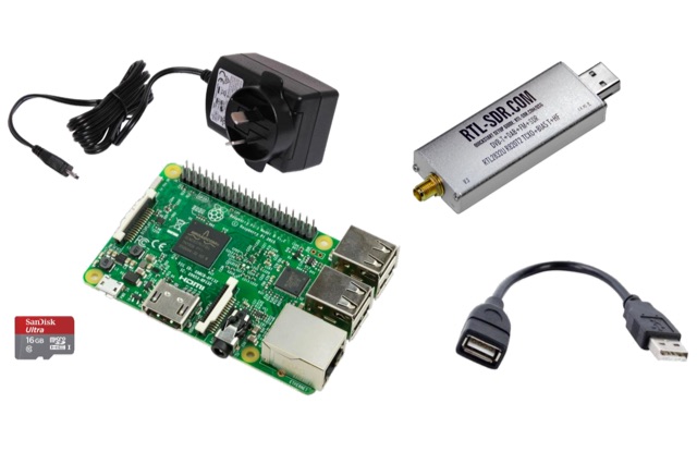 This project is a Software Defined Radio Receiver. It has a frequency range of 24MHz 1.2GHz. It can demodulate AM, FM, USB, LSB with selectable bandwidths of 600, 2400, 2800, 3200 and 6400Hz. Using a simple RTL-SDR Dongle and Raspberry Pi 3 computer using GNU RADIO
 -
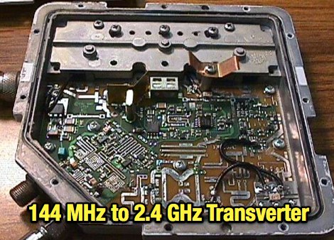
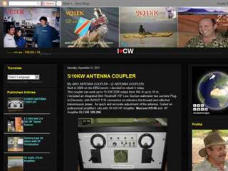
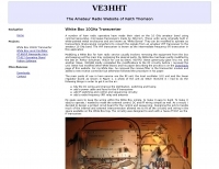
 A synthesized 2.3 GHz Amateur Television (ATV) transmitter design, conceived by Ian G6TVJ, is presented, targeting broadcast-quality video performance on the 13cm band and extending up to 2.6 GHz. The core of the design utilizes a commercial Z-comm Voltage Controlled Oscillator (VCO) that tunes from 2.2-2.7 GHz, providing a +10 dBm output and simplifying RF alignment. This VCO's stability, originally intended for narrowband applications, readily accepts high-frequency video modulation, contributing to the transmitter's robust performance. The exciter stage, incorporating a Mini Circuits VNA 25 MMIC amplifier, boosts the signal to +16dBm, while a Plessey SP4982 prescaler divides the output frequency for the synthesizer. The synthesizer employs a Motorola MC145151 CMOS parallel IC, favored over the common Plessey SP5060 for its superior video modulation characteristics and ease of programming without microprocessors. This choice addresses issues like LF tilt and distorted field syncs often seen with SP5060 designs, particularly when operating through repeaters or over long distances. The MC145151 divides the signal further, enabling precise frequency stepping, with programming handled by EPROMs for channel selection and LED display. The loop filter network, critical for video integrity, was developed through experimentation to prevent the PLL from reacting to video modulation, ensuring a clean transmitted picture. The transmitter incorporates a Down East Microwave commercial power amplifier module, delivering approximately 1.6W output, driven by the exciter through a 3dB attenuator. Construction involves surface-mount SHF components on micro-strip lines etched onto double-sided fiberglass board, housed within a tinplate box. The design boasts no AC coupling in the video path, preserving low-frequency response, a common failing in other ATV transmitters. Performance tests with a 50Hz square wave revealed no LF distortion, and a calibrated "Pulse & Bar" signal showed a near 100% HF response, demonstrating its capability for high-quality ATV transmissions.
 -
 Sw tool to design point-to-point multi-hop microwave links and networks, 400MHz to 58 GHz. Site/Hop Configuration; Customized Antenna & Radio Equipment Libraries; Link Budget; Path Profile Analysis ,clearance, reflections; import path profiles from SRTM maps, free download.
 -
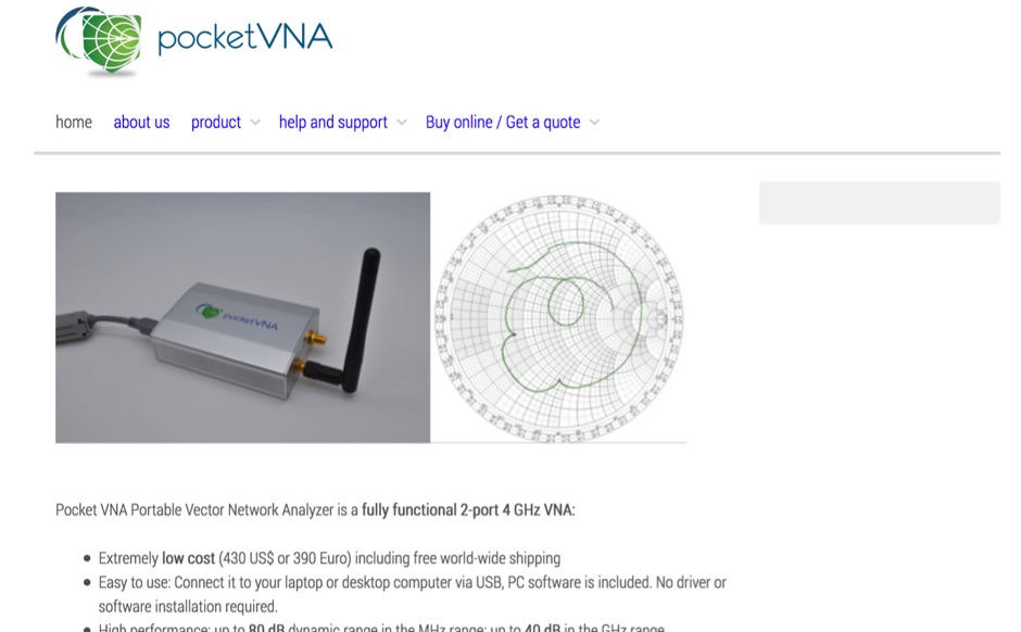 A 500 kHz to 5.5GHz 2-port vector network analyzer designed for use with any Linux, Windows or MacOS computer. High performance: up to 80 dB dynamic range in the MHz range; up to 40 dB in the GHz range
 -
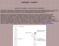
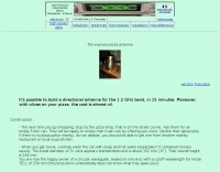 Build a directional antenna for the 1.2 GHz band, in 15 minutes
 -
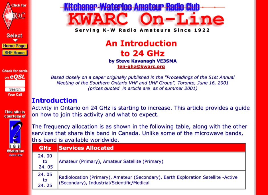 Article provides a guide on how to use 24 GHz band and what to expect, including Active modes, equipment, propagation and antennas for this band in by VE3SMA
 -
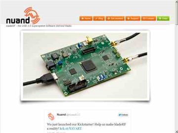 Nuand id the maker of bladeRF - the USB 3.0 Superspeed Software Defined Radio, 300MHz - 3.8GHz RF frequency range Independent RX/TX 12-bit 40MSPS quadrature sampling
 -
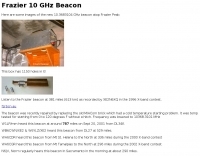
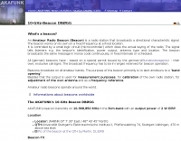 beacon transmits on 10.368,850 MHz in the 3cm-band
 -
 A home made project for an ATV RF power amplifier
 -
-
-
-

-
-
 Constructing a high-performance RF spectrum analyzer up to 1000 MHz requires careful attention to component selection, shielding, and circuit isolation. This resource details a project that improves upon the _Spectrum Analyzer for the Radio Amateur_ design by Wes Hayward (W7ZOI) and Terry White (K7TAU), incorporating ideas from Scotty Sprowls' project, particularly his 1013.3 MHz IF bandpass cavity filter. The analyzer utilizes a Mini-Circuits SRA-11 mixer with a sweeping local oscillator from 1013 to 2013 MHz, feeding into a 4-pole copper pipe cavity filter. The design employs a second SRA-11 mixer with a fixed 1024 MHz LO to produce a 10.7 MHz final IF. This signal then passes through narrowband resolution filters and is processed by Analog Devices AD603 and AD8307 ICs for IF amplification and logarithmic detection, driving an oscilloscope in X/Y mode. The project emphasizes modular construction, using salvaged components and double-sided FR4 material for PCBs, with critical notes on minimizing spurious images through effective shielding and proper voltage regulation for each module. Key components include a Z-Communications V585ME48 VCO for the first LO and a Z-Comm V583ME01 VCO controlled by a Motorola MC145151 PLL for the second LO. An optional Hittite HMC307 step attenuator and K&L 5L121-1000/T5000-O/O low-pass filter manage RF input. Tuning procedures for the 10.7 MHz IF resolution filter are also detailed, showing before-and-after spectrum views.
 -
-
-
 A collection of projects and equiment home made for 24 GHz operations
 -
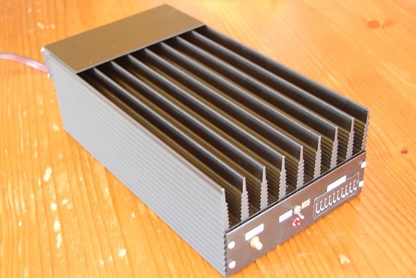
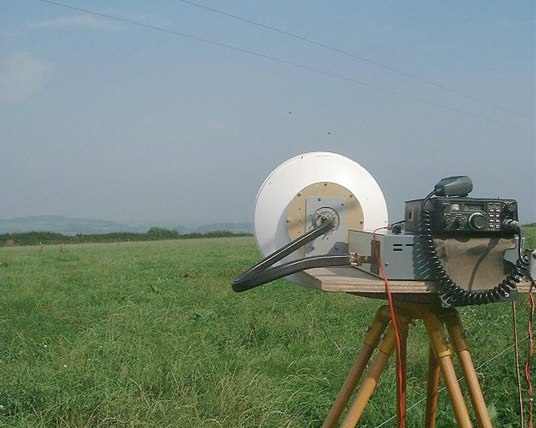
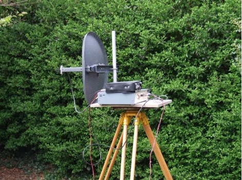 The equipment shown on this page comprises a basic G3WDG transmit and receive system with the addition of a 1W Qualcomm amplifier.