Search results
Query: 40 meter antennas
Links: 78 | Categories: 8
Categories
-
 A dual band dipole antenna for 40 and 80 meters band. Total lenght of 26 meters, foreseen two coils at aprox 11 meters distance from center feed.
 -
 An antenna for 80 meters band for those who does not have enough space to setup a halwave wire dipole that is aprox 130ft or 40 meters. The antenna is an open-wire-fed shortened dipole
 -
 Presents field test results for an **elevated SuperAntenna MP-1** portable antenna, configured on a tripod for HF operations. The resource details the antenna's setup and performance during a portable activation, focusing on its use across the 40-meter, 20-meter, and 17-meter amateur bands. It includes observations on signal reports and operational considerations for this specific portable antenna configuration. The content provides practical insights into deploying the MP-1 antenna in a non-ground-mounted setup, which is often a point of interest for portable and QRP operators. It documents the author's experience with the antenna's tuning and effectiveness for making contacts under real-world conditions, offering a user-perspective review of its capabilities. The article also features photographic evidence of the antenna's deployment, illustrating the tripod mounting and the overall portable station setup.
 -
 A portable (15.5 foot diameter) NVIS loop for 3.5 to 7.3 MHz. Performs well at high and low takeoff angles, and has smaller footprint than most NVIS antennas.
 -
 No exotic claims are made for this antenna. Author just tried a few WSPR experiments on 40 meters and was surprised with the results. What appears below may inspire you to try something equally off-the-wall, to see what happens.
 -
 A portable operation experience with a SpiderBeam pole during a contest, testing wire antennas, like dipole and delta loops configurations on 20 40 and 80 meters band.
 -
 An interesting article on end fed half-wave wire antennas with a couple of original experiments. Author illustrate the role of the QRP matchbox, and a 40/20 meter antenna with a center stub making it a large bandwidth antenna for 40 and 20. Includes also an 80/40 end fed with the typical coil to make it available on 80 merts band.
 -
 Basic magnetic loop antenna examples and loop aerials theory explained. This article inclued some interesting tricks on building magnetic loop antennas and an usefull excell sheet to help compute magneti loop antennas calculating power efficiency from 10 to 40 meters band
 -
 This page describes a comparison study on seven different beam antennas for 40 meters band. Yagi antennas, moxon antennas, mini horse all antennas are described with schema diagram , azimuth plot and SWR F/B Gain diagram
 -
 A quarter wave vertical omni-directional antenna for 7 MHz. Formulas for dimensions in feet and meters are provided. Ideal radial angle is between 35° and 45°. Velocity factor (Vf) varies based on coax type.
 -
 This page describes an entirely simple, One-Knob matchbox that will match this antenna efficiently on 40, 30 and 20m, using a simple circuit that can be switched between series-resonant and parallel-resonant with just one banana jumper
 -
 256 memories enable the _AT-AUTO_ to recall settings across multiple bands, making it efficient for operators who frequently change frequencies. The tuner is compatible with various antennas and amplifiers, such as the Mercury LUX, and integrates seamlessly with radios like the FLEX 6400 using an RS232-USB connection. This integration allows the tuner to follow frequency changes without additional input, enhancing operational efficiency. Despite being out of production, the _AT-AUTO_ remains supported by Kessler Engineering, which offers firmware updates and repair services. The tuner features a cross-needle SWR meter, providing quick visual feedback during tuning. It also includes a QRO keyline circuit to protect amplifiers during tuning. Users appreciate the tuner's ability to track radios via CAT control, avoiding automatic tuning during QSOs, a common issue with other models. The _AT-AUTO_ is praised for its durability and performance, with many users noting its reliability over years of use. Its ability to handle legal limit power and its balanced line output make it a versatile choice for serious operators. Although it lacks some features like multiple coax outputs found in other models, its robust build and continued support make it a valuable tool for HF enthusiasts.
 -
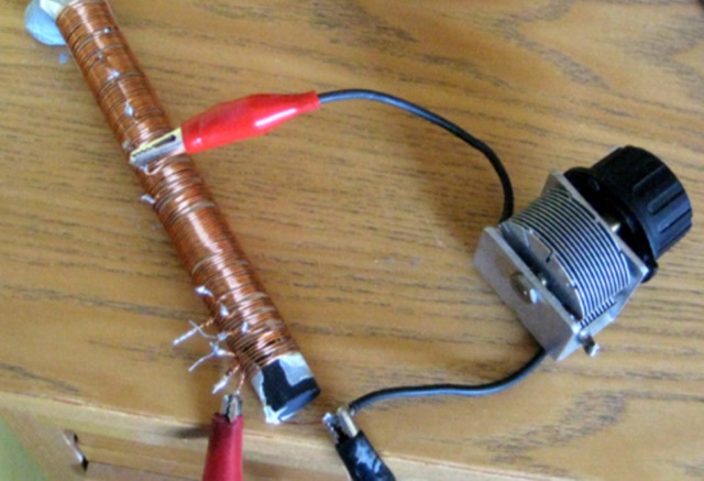
 Experimenting with capacitive antennas for 40 and 80 meters band. A very space-saving antenna with good receivings caracteristics
 -
 Vertical end fed antenna used for portable operations. The antenna will work on 80 with acceptable results, it will work fine on 40m, and it will be a good deal better than a normal 1/4 wave GP on 20, 17, 15 meters.
 -
 Operating in antenna-restricted communities presents unique challenges for amateur radio operators, often necessitating creative solutions for antenna deployment. This resource details the design and implementation of stealth antennas within a townhouse community in Exton, PA, where external antennas were strictly forbidden by covenants. The author, WB5NHL, describes his setup, which involved locating the shack in the basement and utilizing an unused space under the roofline of a finished third-floor loft for antenna placement. The content specifically addresses the practicalities of routing coax cables three floors and maximizing antenna performance within limited attic space. It covers solutions for multi-band operation, including dedicated sections for 40-10 meter and 80-meter antennas, along with strategies for mitigating potential interference issues. The approach emphasizes full compliance with community covenants, achieving maximum height-above-ground for horizontal antennas, enabling instant band switching, and efficiently utilizing available attic volume. While acknowledging limitations such as potential interference with high power and fixed antenna patterns, the resource provides a detailed account of a functional compromise for restricted environments. Links to individual pages on _coax cables_, _40-10 meter antennas_, _80-meter antennas_, and _interference issues_ offer deeper dives into each specific aspect of the installation.
 -
 Experimentin wire antennas on top band using several type of aerials. This includes a 40 to 160 meters EndFed Half Wave kite antennas and 160m/80m loaded vertical antenna.
 -
 This article documents the author's journey in building, modifying, and testing a DIY short vertical antenna for 40, 30, and 20 meters, with potential 80m capability. Initially inspired by Parks On The Air (POTA), the author explores pedestrian mobile operation and details various experiments to enhance antenna performance. The piece highlights challenges, SWR tuning, portability, and practical results, emphasizing a balance between efficiency and size. Ultimately, it showcases the adaptability of DIY antennas for portable ham radio applications.
 -
 Learn how to design and analyze a folded trifilar antenna for the 80-meter band. Based on a description from RAF antennas between 1940 and 1970, this article provides step-by-step guidance on modeling the antenna, calculating resonance frequency, adjusting dimensions, and verifying performance. Perfect for hams looking to improve their antenna setup for better transmission and reception on the 80M band.
 -
 This antenna is designed for 40, 80 and 160 meters to complement a tri-band beam normally taken on DX peditions for 10, 15 and 20 meters, so six bands can be worked with only two antennas.
 -
 Discover the best low band receive antennas for hams with limited space. Learn about the K9AY loop antenna and Shared Apex Loop Array, two alternatives to the traditional Beverage antenna. Understand the concept of Relative Directivity Factor (RDF) and compare the performance of different receive antennas. See how the Shared Apex Loop, patented by Mark Bauman (KB7GF), offers an RDF between 8 and 10dB. Find out how to optimize antenna performance and enhance your receive capabilities on 160, 80, and 40 meters. Explore the world of low band receive antennas with insights from WB5NHL Ham Radio.
 -
 This article details a ham radio operator’s experience setting up HF antennas in an antenna-restricted community. Initially using an AEA Isoloop magnetic loop for QRP PSK, the author later built an attic antenna system, including dipoles for multiple HF bands and a slinky dipole for 40 meters. The setup allowed for operation on six bands with acceptable VSWR. Despite space constraints and some compromises, performance was effective. The article highlights practical strategies, emphasizing experimentation and antenna modeling for optimizing performance in limited-space environments. A valuable guide for ham radio operators facing similar restrictions.
 -
 Learn how to build your own QRPGuys DS-1 40-10m short vertical antenna for ham radio operators. This page provides detailed instructions on constructing this antenna, which covers the 40 to 10-meter bands. Whether you're a beginner looking to get started with antenna building or an experienced ham radio operator looking for a new project, this resource is useful for anyone interested in DIY antennas for portable or QRP operations.
 -
 This page provides guidance on designing an End-Fed Half-Wave (EFHW) or Random-Length antenna for amateur HF bands, such as 80 or 40 meters. The content explains how to optimize the antenna for multi-band use and match it to a 50-ohm system using an unun. Hams can generate radiation patterns, VSWR charts, and antenna current diagrams for their customized antenna designs. Understanding how antenna dimensions affect performance is essential for successful field operations. The page caters to ham radio operators looking to build efficient and effective HF antennas for their stations.
 -
 Demonstrates the construction and portable deployment of a 40-meter horizontal loop antenna, often referred to as a "Sky Loop" or "DX-Buster." The design adapts a full-wavelength horizontal loop for field use, eliminating the need for traditional insulators by employing four 5-meter heavy-duty _squid poles_ and metal post bases for support. This setup facilitates rapid assembly, crucial for portable operations, with the antenna wire length specified at approximately 43-45 meters for optimal 40-meter band performance. The resource details the specific construction methodology, including winding the antenna wire around rubber caps on the squid poles and securing it with electrical tape. It provides a parts list and assembly techniques, focusing on minimizing components for ease of transport and quick setup. The article, originally published in the February 2013 edition of the Central Coast ARC "Smoke Signals" magazine, reflects practical experience. This documentation offers a field-deployable 40-meter loop antenna solution, utilizing readily available components like fiberglass squid poles. It presents a practical approach for operators seeking a robust, portable antenna for the 40-meter band, emphasizing simplicity and efficiency in its design and deployment.
 -
 This page provides information on how to design an Off-Center-Fed Dipole (OCFD) antenna, suitable for amateur HF bands like 80 meters or 40 meters. The antenna design allows for VSWR minima on multiple bands, making it a good choice for multi-band use. Learn how to create an OCFD antenna in either flat-top or inverted-Vee form using a single support. The page also offers tools to generate radiation patterns, VSWR charts, and antenna current diagrams for your specific antenna design, helping hams understand performance factors. Ideal for ham radio operators looking to build their own effective antennas.
 -
 The ICOM IC-705, a popular QRP transceiver for portable operations, often presents unique challenges for field deployment. This resource details practical solutions for common portable setup issues, particularly for _Parks on the Air_ (POTA) activations. It describes a custom bracket for connecting antennas to the IC-705 through a backpack's antenna flap, utilizing a BNC female-to-female chassis mount connector to mitigate cable tangles. The author shares experiences with a DIY magnetic loop antenna, noting its ease of tuning with the IC-705 and successful CW contacts on 40 and 20 meters over distances exceeding **1000 miles**. Another modification presented is a strain relief solution for the microphone cord, replacing the standard spring clip with an easier-to-attach method. The page also mentions using a _Wolf River Parks antenna_ for POTA activations and references the QRPGuys DS-1 antenna as another portable option. Firmware updates and integration with an LDG Z11-Pro II auto-tuner are also discussed.
 -
 VE1ZAC's analysis details the performance of **MFJ927** and **SGC239** autotuners with portable HF vertical antennas, specifically comparing 31 ft and 43 ft configurations. The resource originated from challenges encountered during a Maritime QSO Party roving operation, necessitating a lightweight and easily deployable antenna system. Target bands for the contest included 80, 40, 20, 15, and 10 meters, with a maximum power handling of 100 W CW. The author utilized a 30-foot carbon fiber push-up pole to support a vertical wire element, noting its 2 lb weight and reliability. EZNEC modeling was employed to predict performance, showing favorable results for a 30-foot vertical with elevated radials, particularly on 40 and 20 meters. Feedpoint impedance measurements, taken with an AIM4170C, are presented for various HF bands, both with and without a 41-foot RG6 stub designed to reduce reactance on 80 and 20 meters. The stub significantly improved matching on these bands, easing the tuner's workload. Operational tests revealed issues with the MFJ927's reliability during contest setup, leading to reliance on the K3's internal tuner. The SGC239, tested post-contest, performed flawlessly. A detailed side-by-side comparison covers mechanical aspects, connection options, power bias, impedance range, board quality, and documentation. Modifications to the MFJ927, including a new aluminum case, white paint for heat reduction, and upgraded impedance-measuring resistors, are also described.
 -
 This resource presents a non-rigorous evaluation of the front-to-back (F/B) ratio of short Beverage antennas, specifically designed for low-band operation on frequencies such as 160, 80, 40, and 30 meters. The author, VE1ZAC, details the methodology used to measure the F/B ratio, which involves using a Millen Grid Dip Oscillator as a portable signal source. Measurements were taken by switching the antenna direction and recording S Meter and preamp readings to derive gain numbers. The document discusses the challenges faced in achieving accurate measurements and the assumptions made during the process, such as the calibration of S Meter units at 6 dB. This evaluation is particularly relevant for amateur radio operators interested in antenna performance on low bands.