Search results
Query: nec
Links: 941 | Categories: 66
Categories
- Manufacturers > Cable and Connectors
- Shopping and Services > Cables and Connectors
- Technical Reference > Coax Cables and Connectors
- Ham Radio > Clubs > North America > USA > Connecticut
- CB Radio > Clubs > Alfa Tango
- Operating Modes > Packet Radio > Beginner's Guide
- Ham Radio > Clubs > North America > Canada > British Columbia
- Ham Radio > Clubs > North America > USA > California
- Ham Radio > Clubs > North America > Canada
- DX Resources > Ham Radio Awards > Castle Awards
- Ham Radio > Clubs
- Operating Modes > Morse code > Clubs
- Operating Modes > Satellites > Clubs
- Operating Modes > Radio Direction Finding > Clubs
- Ham Radio > Clubs > North America > USA > Colorado
- Ham Radio > Clubs > Contest Clubs
- Operating Modes > D-STAR > D-Star Clubs
- Ham Radio > Clubs > Technical Specialty > Digital Modes Clubs
- Software > DX Cluster
- Software > Linux > DX Cluster Clients
- Software > Macintosh > DX Cluster Clients
- Ham Radio > Clubs > Europe > UK > Eastern England
- Operating Modes > Internet Linking > EchoLink
- Ham Radio > Elmers
- DX Resources > Nets > Emergency Nets
- Internet and Radio > Forums
- Ham Radio > Regional > Italy > Forums
- Ham Radio > Clubs > North America > USA > Hawaii
- Ham Radio > Clubs > Societies
- Ham Radio > Clubs > North America > USA > Illinois
-
 A self-supporting vertical antenna design for stationary-mobile HF-VHF operation is presented, emphasizing ease of construction with common materials like a fiberglass fishing rod and PVC pipe. The design focuses on creating a set of no-tuner monoband radiators for bands such as **2m**, **6m**, 10m, and 12m, with an overall radiator support length of 3.3m. The construction process details the assembly of the antenna base using a magnetic mount, PL-259 connector, and PVC pipe sections, which then supports the telescopic fishing rod. Radiator extensions are cut to achieve quarter-wave resonance on specific bands, with detailed instructions for 6m (50-51 MHz), 10m (28.5 MHz), and 12m (24.9 MHz). For lower HF bands like 15m, 17m, and 20m, the design incorporates base-loading coils, with specific turn counts provided (e.g., 21 turns for 20m). The project also suggests using an _antenna analyzer_ for precise tuning of extensions and coils, moving beyond theoretical values to achieve optimal performance. The author, _IK1ZYW_, notes that for 80m and 160m, the antenna becomes less efficient as a vertical, suggesting alternative configurations like an inverted-V dipole or asymmetrical inverted-L.
 -
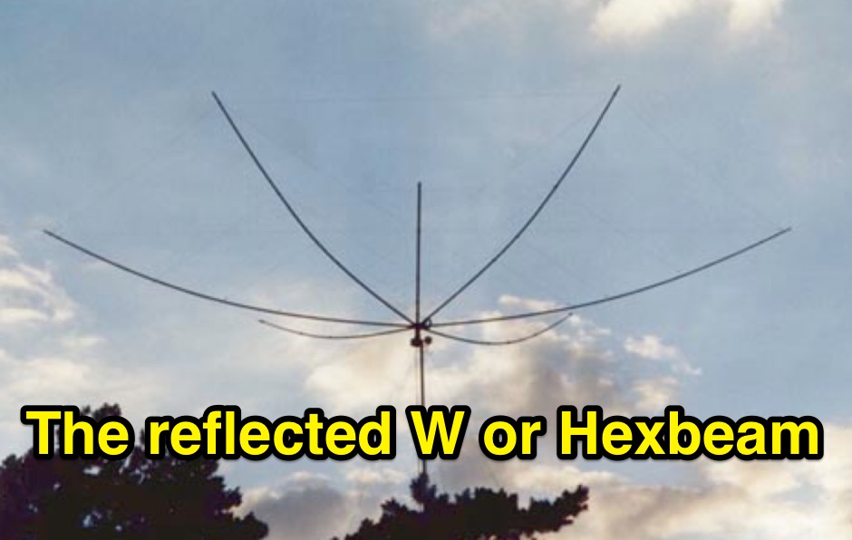 Hexagonal Wire Beams for 40-10m from DL7IO, different mono/multiband designs with building descriptions and model files for EZNEC
 -
 HF Wire Yagi antenna with notes and eznec file on original article of a Portable 3-Band Yagi antenna for 10-15-20 meter band made with wire elements. Include link the original to QST article.
 -
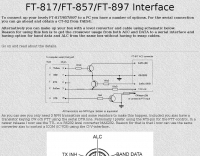 To connect up your FT-817/857/897 to a PC you have a number of options. For the serial connection you can go ahead and obtain a CT-62 from YAESU. Alternatively you can make up your box with a level converter and cable using schematic in this page
 -
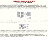 Demonstrates the construction of a **remote antenna tuner** utilizing a standard radio-controlled (RC) servo mechanism to adjust a variable capacitor. The design focuses on enabling remote tuning for narrow-bandwidth antennas, specifically mentioning frame and packing crate antennas, from within the shack. It covers the mechanical arrangement for integrating the servo with a capacitor and provides a circuit diagram for a control unit that generates the necessary 0.5mS to 1.5mS pulse-width modulation (PWM) signals to drive the servo's 180-degree rotation. This setup was successfully tested with up to 20 watts RF power without arcing or adverse effects on the servo, though tuning was performed at 1 watt for VSWR readings. The resource highlights the use of inexpensive, readily available components, such as Futaba servos, and details critical considerations like power supply decoupling with a 47uF capacitor to prevent unintended servo movement upon power-off. The system provides a practical solution for optimizing antenna performance for specific frequencies without manual adjustment at the antenna itself.
 -
 For amateur radio operators utilizing _APRS_ or requiring an external antenna for their GPS receiver, this resource details the construction of a compact, circularly polarized mobile antenna. The design is based on a classic turnstile configuration, employing two dipoles rotated 90° from each other and spaced a quarter-wavelength above a ground plane. A parallel-plate transmission line, fabricated from printed circuit board material, serves as both the connection method and mounting post for the dipoles, simplifying the feed network for circular polarization at 1.57542 GHz. The article outlines the fabrication process, starting with a 4-inch diameter hobby tin or brass base plate and #14 solid copper wire elements. It specifies using _RG-58/U_ or similar 50-ohm coax, with an 8-foot maximum length to minimize loss at the GPS frequency. The parallel-plate transmission line is constructed from two 2-inch lengths of single-sided _FR-4_ or G10 PCB material, 0.062-inch thick, with a specific 45° microwave turn cut on the active side. Final assembly involves an 8-ounce cream cheese container as a radome, and the article discusses the self-phased quadrature feed method to achieve circular polarization without a coaxial phasing line, resulting in an omnidirectional pattern suitable for GPS satellite reception.
 -
 The Flower Pot Antenna project details a portable dual-band antenna primarily operating on 10 meters, with secondary resonance near the 30-meter band. Construction involves winding RG58 coaxial cable uniformly around a large plastic flower pot, approximately 70cm high with a 60cm top diameter. The design eliminates the need for radials, contributing to its compact and lightweight nature. Key construction steps include soldering the inner conductor to the shield at one end of the wound cable and connecting the wound cable's shield to the rig cable's inner conductor at the base. An LC network, comprising a variable capacitor (0-200pF) and an inductor (10 coils, 5cm diameter, 2mm wire), is inserted between the wound cable's inner conductor and the rig cable's shield. Tuning is performed with an antenna analyzer, adjusting cable length and the variable capacitor for optimal impedance on 10 meters. The antenna performs effectively when installed horizontally.
 -
 Constructing a **reduced-size coaxial Moxon rectangle** antenna for the 17-meter band is detailed, presenting a method to achieve a compact directional antenna. The resource outlines the use of RG-58/U coaxial cable for elements, enabling a substantial reduction in physical dimensions compared to traditional wire or tubing Moxon designs. It provides specific instructions for tuning coaxial elements using an **MFJ-259B antenna analyzer**, including a formula to calculate trimming lengths based on measured resonance and desired frequency. The article explains how to prepare the coaxial cable for both driven and reflector elements, specifying connections for testing and final assembly. Performance data from an MFJ-259B shows SWR readings between 1.0 and 1.2 across 18.068 MHz to 18.168 MHz, with R values from 51 to 59 ohms and X values of 0 or 6 ohms. The antenna's power handling is approximately 500 watts continuous, limited by the RG-58/U coax. Comparative receive testing against an All-Band Sterba Curtain at 50 feet indicated a 2 S-unit reduction for the coaxial Moxon at 9 feet, suggesting optimal performance at a height of 34-40 feet for a 15-18 degree take-off angle. The design achieves an electrical quarter wavelength with over 30 percent size reduction.
 -

-
 Demonstrates adapting the _Moxon rectangle_ antenna design for 2-meter VHF operation, highlighting its unique characteristics for specific applications. It details how the antenna's small size and distinctive far-field pattern, typically associated with HF, can be effectively utilized on VHF. The resource provides modeled dimensions for three different element diameters (1/4", 1/2", 1") and discusses the necessary adjustments to maintain optimal performance, such as gap spacing and element lengths, to achieve a 50-Ohm feedpoint impedance. The article presents predicted performance data, including gain (dBi), front-to-back ratio (dB), and feedpoint impedance (R, jX) across 144, 146, and 148 MHz. It analyzes free-space azimuth patterns and discusses the antenna's behavior when horizontally and vertically polarized over ground, including its suitability for fixed installations, repeater applications, and even satellite communications. Construction considerations, such as bending elements and maintaining critical gap distances, are also addressed. Furthermore, the content explores advanced configurations like using two back-to-back rectangles for broader coverage and a crossed-Moxon setup for circular polarization, suggesting potential for urban communication and satellite work. The author, _L. B. Cebik, W4RNL_, emphasizes the Moxon's strengths in broad bandwidth, wide beamwidth, and high front-to-back ratio, rather than maximum gain.
 -
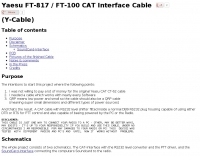 Connect your FT-100 or FT-817 to your pc with this CAT interface cable
 -
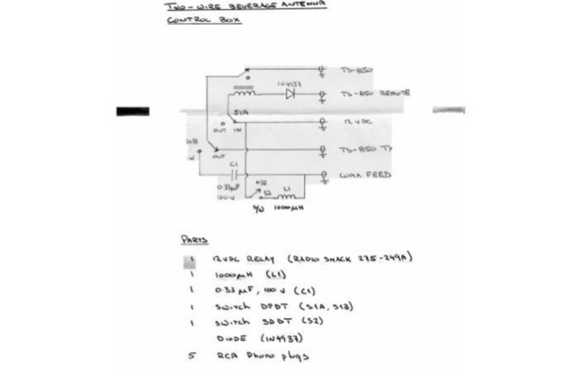 Two Wire Beverage by Jeff Parke, describes a two-wire Beverage antenna design for improved reception with switchable direction (forward/backward) and lower noise level. It includes details on building the antenna, matching transformers, and a control box for selecting direction and connecting to the receiver.
 -
 A **mobile HF multiband antenna** project details the construction of a center and top-loaded design, optimized for 10 through 80 meters. This antenna incorporates a capacity hat positioned high on the whip for enhanced efficiency, differing from commercial bugcatcher designs. The coil construction prioritizes high Q and minimal loss through an air core, open spacing, and heavy gauge wire, contributing to its lightweight nature and suitability for portable operation with a proper counterpoise. Band switching is achieved by manually moving a jumper plug to various tap points on the coil, allowing for operation across multiple bands, with 17m being resonant when the coil is bypassed. The design, a result of nine months of experimentation by N1LO, includes detailed instructions for modifying a Hamstick antenna base, creating a jumper wire, and assembling the capacity hat using stainless steel wire and silver-bearing solder for robust connections. The loading coil utilizes nylon grommet strips around a PVC pipe for an air-core winding, ensuring high efficiency. Tap sockets are fashioned from silver-plated 5-way binding posts, providing low-resistance RF joints for band selection. Guidance on tap point determination emphasizes using an antenna analyzer like the MFJ 259B or 269 to achieve resonance, especially on 40m and 80m where feedpoint resistance can be low. The document also covers the installation of monofilament stays to maintain antenna uprightness at highway speeds, with specific attachment points for stability.
 -
 Your source for coax, connectors, wire, baluns, and other certified quality wireman products.
 -
 The _Morgain_ antenna for 40/80 meters is a straightforward and cost-effective wire antenna design, requiring careful tuning for optimal performance across two bands with low SWR. Construction involves creating 12 cm PVC spacers with three holes for wire insertion, along with larger terminals for anchoring and connector housing, which should be sealed with silicone. The provided measurements detail the specific lengths for the antenna elements, crucial for achieving resonance on both 40m and 80m bands. Tuning the Morgain antenna necessitates fabricating four wire segments with pins to temporarily connect and adjust the bridging points symmetrically for both 40m and 80m. This iterative process, though time-consuming, ensures the antenna functions effectively for decades once the precise connection points are soldered and protected. The design emphasizes ease of construction and long-term stability, making it a practical solution for hams seeking a dual-band wire antenna.
 -
 This drawing shows a simple 10 meter wire J-pole antenna designed for 28.4 MHz. It is a vertical, end-fed Zepp-style antenna made from common materials and intended for easy home construction. The main radiating element is a straight length of stranded copper wire, either 14 or 18 gauge, cut to about 16.5 feet. At the top, the wire is supported by an insulator, allowing the antenna to be hoisted vertically. The matching section is made from 450-ohm ladder line, approximately 7 feet 9.5 inches long, and shorted at the bottom. This matching stub transforms the impedance so the antenna can be fed with coaxial cable. The feed point is tapped about 6 inches above the bottom of the stub, with the shield and center conductor connected at the proper points. A choke balun is formed with five turns of RG-58 coax in a 4-inch diameter loop to help reduce unwanted RF on the feed line. The drawing notes that this antenna has about 0 dBd gain, similar to a dipole, but offers an omnidirectional pattern and low-angle radiation when installed high. Its main advantage is practical performance, simple construction, and effective coverage for 10 meter operation.
 -
 Long range Wi-Fi antennas you can build. Helicals, parabolics, and biquads discussed. How to add external antennas to WUSB54GC and F5D7050 usb wireless adapters for long range connections.
 -
 M1PAF's 20 Meter Vertical Moxon antenna design, based on Pete Mills' EZNEC model, utilizes a push-up GRP mast and Tufnol plate for mounting cross arms, minimizing metallic elements within the beam. Hydraulic pipe clamps, also plastic, secure the tube clamps, with only two bolts and a plate being metallic. Dog bone insulators with Kevlar line and snap links facilitate quick wire element attachment, ensuring tension in all dimensions. The antenna's support structure includes Tufnol guying rings for Kevlar guys, providing stability against high winds. The cross arms are constructed from three 1-meter sections, allowing for convenient packing. This portable setup was successfully deployed adjacent to the ocean, enabling over 4500 QSOs in six days with 100W, achieving easy contacts into Japan and Asia. The design emphasizes ease of erection by a single operator and robust performance in challenging environments. Components for the cross arms were sourced from Spiderbeam. Further information is available via M1PAF's QRZ.com details.
 -
 This page discribes microphone wiring connections for most UK and foreign radios. Most U.S. radios are "Code Type 2".
 -
 The _Astron RS35m Power Supply Schematic_ provides a detailed circuit diagram for this popular linear power supply, focusing on the rectifier and pass transistor stages. It presents the AC input and DC output sections, illustrating the component layout and interconnections critical for understanding its operation. The schematic is enhanced with specific annotations derived from the December 2005 QST "Hands-On Radio, Experiment #35 Power Supply Analysis." These notes offer insights into the circuit's functionality and potential analysis points, making the diagram more instructive than a bare schematic. The resource serves as a practical reference for hams interested in the internal workings or maintenance of the _Astron RS35m_ unit. This document specifically highlights the key components responsible for voltage regulation and current delivery.
 -
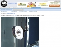 Sardine Can Antenna. is a BiQuad or Bi circle - wire length each side (8 x 1/4 waves ) 31 mm
 -
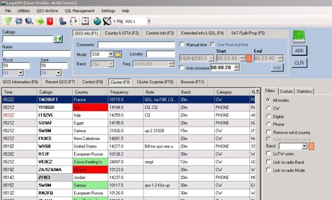 Log4OM is a free logging software designed for amateur radio operators who require an integrated environment for station management and QSO logging. It is widely used by DXers due to its strong database capabilities and its integration with common online services. The program uses a structured SQL database and supports large logbooks without noticeable performance degradation. One of its key features is **CAT Control**, which allows direct communication with many transceivers for automatic frequency and mode detection. The **DX Cluster Client** provides real-time spotting with filtering and band/mode tracking, helping operators quickly identify new DX opportunities. Log4OM integrates with several external confirmation systems. Built-in support for **Logbook of The World (LoTW)** and **eQSL** allows automatic upload and download of confirmations. The software also includes **Award Tracking**, enabling operators to monitor progress toward DXCC and other award programs directly from the log. Additional capabilities include **Callbook lookup** via services such as QRZ, **ADIF import/export**, and customizable **QSL management** for both electronic and paper cards. The interface is modular, with panels that can be arranged depending on operating preferences. Log4OM does not include integrated digital mode engines, so digital operation normally relies on external programs such as WSJT-X or FLdigi connected through standard interfaces. Overall, Log4OM provides a comprehensive logging environment suitable for both casual operation and serious DX chasing, with a feature set comparable to many commercial logging applications.
 -
 Hong Kong's only full-service amateur radio store. Full line of Amateur Radio and Two-way equipment and accessories from companies such as Yaesu, Icom, Kenwood, Motorola, MFJ, Alinco, Diamond, AOR and many, many more. Knowledgeable staff with many years of experience in the radio business TAX-FREE shopping (no sales, VAT, GAT or other taxes) HF, VHF, UHF transceivers, receivers, walkie-talkies, antennas, antenna tuners, coax and connectors
 -
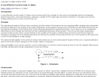 A cost effective current-mode 1:1 balun can be constructed from a length of coax and a rod typically used for a broadcast antenna loop-stick, some electrical tape, cable ties, a length of PVC water-pipe and some connectors.
 -
 Demonstrates the construction and on-air performance of the _NB6Zep_ antenna, a modified 20-meter Extended Double Zepp design optimized for multi-band operation from 40 through 10 meters. The resource covers basic design principles, including dimensions of 66 feet horizontal and 5 feet vertical elements, and specifies open ladder line or TV twin lead for the transmission line. It details material selection for low-cost wire antenna construction, such as 18 AWG wire for the legs and ceramic or plastic insulators, along with practical tips for soldering connections and insulating against moisture. The author, NB6Z, shares insights from extensive _EZNEC_ modeling to optimize the antenna's total length for a 40-meter half-wave dipole footprint and feed line length for direct tuner connection. The article presents field results, including successful _PSK31_ contacts from Oregon to the East Coast on 40 and 30 meters with 50 watts, even at a low height of 6 feet. It provides detailed performance characteristics for each band, noting the _NB6Zep_'s highest gain (over 3 dB) and sharp, medium-angle lobes on 20 meters, which yielded strong DX reports to locations like Korea, Japan, and Argentina. For 17 and 15 meters, it describes a butterfly-like pattern with broad lobes, while 12 and 10 meters exhibit narrow, directional lobes in an "X" configuration. The author also shares personal experiences operating successfully for over a decade in an antenna-restricted environment using the NB6Zep and other stealth wire antennas.
 -
 Presents a catalog of **QRP** transceivers, antenna tuners, and related accessories for amateur radio operators. The product line includes the ZM-2 antenna tuner, designed for efficient impedance matching across HF bands, and the NW-series QRP transceivers, offering low-power CW operation. Additionally, the site details various ladder line insulators and specialized connectors, emphasizing robust construction for field deployment and home station use. Each product listing provides specifications, operational parameters, and pricing information. Compares the features of different **QRP transceiver** models, such as the NW-40 and NW-20, highlighting their respective band coverage and power output capabilities. The ZM-2 tuner's performance is detailed with typical SWR reduction figures for various antenna types, demonstrating its utility for portable and fixed stations. Customer testimonials and product images illustrate the practical application and build quality of EMTECH's offerings, providing insights into their durability and ease of integration into existing amateur radio setups.
 -
 Presents a detailed construction guide for a 2-element _Moxon rectangle_ antenna optimized for the 10-meter band, designed by L. B. Cebik, W4RNL (SK). This resource demonstrates how to build a compact beam antenna using readily available hardware store aluminum tubing, fitting within a 12-13 foot width. It highlights the antenna's performance characteristics, including a gain comparable to a 2-element Yagi (11+ dBi) and a front-to-back ratio exceeding 20 dB between 28.3 and 28.5 MHz, with an SWR below 2:1 across the entire band. The design emphasizes direct 50-ohm coax connection without a separate matching system, though a 1:1 choke _balun_ is recommended. The guide provides practical advice on element construction, corner fabrication using L-stock or radius-bent tubing, and the critical side-to-side length adjustment for SWR optimization. It details the feedpoint assembly using a chassis-mounting coax connector and discusses element-to-boom plate options, including spar varnished plywood or LE plastic. The author's experience with a test model on a 20-foot mast confirms stable feedpoint characteristics and excellent performance even at lower heights. The document also includes insights into the antenna's free-space azimuth patterns, noting a broad forward lobe and significant front-to-back rejection. It contrasts the Moxon with traditional Yagis, positioning it as an effective, home-buildable alternative for compact sites or _Field Day_ operations, particularly beneficial during periods of increased 10-meter activity.
 -
 The latest and best yagi beams for 432MHz tested and optimized with NEC
 -
 The KD6WD Moxon Antenna Project details the construction of 50-ohm two-element wire beam antennas, specifically Moxon rectangles, for the 10, 15, 17, and 20-meter bands. It utilizes AC6LA's software for critical measurement calculations (A-E) based on center frequency and wire size. Construction involves 16-gauge silver-coated copper wire, 16-foot telescoping fiberglass crappie fishing poles as spreaders in an "X" configuration, and various hub designs including aluminum tubing or PVC joints. A 1:1 current balun is used at the feedpoint, with wire nuts for connections, often achieving a 1:1 SWR across the design band. The project highlights practical applications, such as running a kilowatt into the antennas for greyline DX contacts, consistently yielding excellent signal reports. Comparisons to quad loops show 4 to 5 S-unit improvements in both receive and transmit. The Moxon design, according to L.B. Cebik's analysis, offers superior forward gain and front-to-back ratio among wire beams. The author notes a "DX-Vane" effect where a freely suspended Moxon automatically points to the strongest DX signal. Attempts at dual-band operation (17/20 meters) with a single feed were unsuccessful, reinforcing the Moxon's monoband nature, with EZNEC plots provided for a 17-meter Moxon at 30 feet.
 -
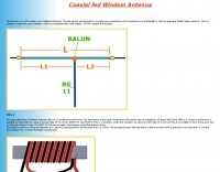 The Windom is an Off-center wire multiband Antenna. The old version was fed just by a single-wire connected on 1/3 of antenna's overall length or with an open-line feeder (later versions). Here is another model with coaxial feeder, which is compatible with Solid States - 50 Ohm output transceivers .
 -
 WB2VUO presents a practical examination of effective HF mobile antennas, focusing on the inherent efficiency challenges encountered on the lower bands, specifically 160, 80, and 40 Meters. The resource delves into the necessity of loading coils for mobile operation below 21 MHz, where full-sized antennas are impractical. It contrasts base-loaded and center-loaded designs, noting that base-loaded antennas are simpler for the average ham to construct but offer lower efficiency compared to center-loaded configurations. The author provides specific data for an 8-foot whip, detailing its electrical length and _radiation resistance_ across various HF bands, from **0.08 ohms** on 160 Meters to **16.1 ohms** on 12 Meters. This data highlights the extremely low radiation resistance on lower frequencies, which significantly impacts feedpoint impedance due to ground and feedline losses. The discussion includes practical considerations for feedpoint impedance, noting that a typical 8-foot whip on 10 Meters might present 30-45 ohms, allowing for acceptable SWR without an ATU. Construction sketches illustrate both base-loaded and center-loaded mobile antennas, with advice on material selection like galvanized steel for rugged bottom sections. The article also includes coil value charts from the _ARRL Mobile Manual_ for both base and center loading, emphasizing the importance of using large diameter wire to minimize losses and suggesting capacity hats to reduce coil inductance and improve performance on 160-40 Meters.
 -
 Selecting an appropriate antenna system for shortwave broadcasting involves evaluating various types based on performance, cost, and operational parameters. This resource details the critical specifications for broadcast antennas, including average and peak power ratings, directivity, takeoff angle (TOA), horizontal beamwidth, and gain, emphasizing that a 100-kW transmitter requires an antenna rated for 150 kW average and 400 kW peak. It clarifies that low TOA signals travel thousands of kilometers, while high TOA is for local coverage, and nearly all modern shortwave broadcast antennas are horizontally polarized. The article explores specific antenna types, such as Log-Periodic Antennas (LPAs), which offer wide frequency ranges (e.g., 2-30 MHz) and directional patterns with 11 dBi gain, costing from $20K to over $100K for multi-curtain versions. Dipole arrays, also known as curtain antennas, are prevalent in international broadcasting, featuring steerable beams (±15° and ±30°) and mode-switching capabilities to alter TOA, with high/low pairs costing over $1 million. Fan dipoles are noted for omnidirectional patterns, smaller size, and lower cost for low-power applications, while rhombics, though simple, require resistive termination and incur several dB of I2R losses. Balun considerations are crucial, as most communications baluns are not rated for the higher average and peak powers of AM broadcast transmitters. Modern shortwave antennas utilize durable materials like Alumoweld wire rope for radiators and support elements, avoiding copper, fiberglass, or materials prone to stretching or deterioration. Feeder systems for high-power stations often require tapered-line baluns to convert 50-ohm unbalanced power to 300-ohm balanced for connection to the antenna.
 -
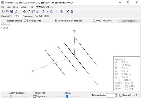 MM Antenna Analyzer by JE3HHT Makoto Mori based on the moment method, which was introduced in MININEC. Download MMANA Free from this page that offer download of basic version and link to the MMANA pro version.
 -
 Reducing noise to your antenna can gain your aerial performance, learn how.
 -
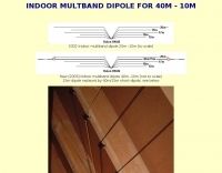 Indoor multiband dipole with EZNEC data files for simulation and analysis. Includes details on construction, tuning, SWR plots, and software usage. This page includes two different dipoles, a first version for 20-10 meters and an extended version covering 40-10 meters allowing a full coverage of most used ham radio HF Bands.
 -
 One common challenge in antenna systems is mitigating common-mode current on the feedline, which can distort radiation patterns and introduce RF in the shack. This project details a 1:1 balun design that ingeniously avoids traditional ferrite beads, often a costly component, by substituting them with steel wool. The steel wool, when integrated into the balun's construction, effectively attenuates unwanted RF on the outer braid of the coaxial cable, ensuring that the antenna radiates efficiently and as intended. The construction involves winding coaxial cable through a PVC former, with the steel wool strategically placed to provide the necessary common-mode impedance. This method offers a practical and economical alternative for hams looking to build effective baluns without the expense or availability issues associated with ferrite cores. The design principles focus on creating a balanced feed to the antenna, crucial for optimal performance of dipoles and other balanced radiators. Experimentation with such designs can lead to improved field results, particularly for those operating with limited budgets or seeking innovative solutions for their antenna systems. The simplicity of using readily available materials like steel wool makes this a compelling build for many radio amateurs.
 -
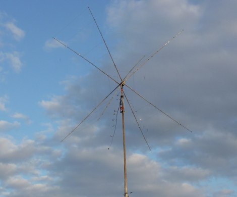 This Multiband Cubical Quad antenna a boomless Quad design with glass-fibre arms and a single coax wire connected to a remote antenna switch. This aerial work on 8 bands and has a 60-degree beam width. Despite achieving critical technical requirements, the antenna's three-dimensional structure presents obstacles, such as installation issues on fixed towers and risk of frost damage. The spider framework is built of stainless steel, with a compact 18-inch boom and strong angle iron arms. Tait use a variety of methods to fasten element wires and suggests placing them on the outside of the spreaders for improved insulation. The use of nylon twine or parachute cord between key attachment points allows for adjustable separation between pieces.
 -
 provides much greater flexibility in the construction, analysis, and interpretation of radiating structures using a rewritten NEC module.
 -
 Over 65 years of radio manufacturing experience underpins Icom's extensive product line, ranging from handheld VHF/UHF transceivers to sophisticated HF base stations. The company's global website serves as a central hub for product information, technical specifications, and support resources for its diverse range of communication equipment. Hams can explore detailed specifications for popular models like the _IC-7300_ and the _IC-9700_, alongside commercial and marine radio offerings. The site provides access to product catalogs, firmware updates, and user manuals, ensuring operators have the necessary documentation for their Icom gear. Information on new product releases and technological advancements in radio communication is regularly updated, reflecting the company's ongoing commitment to innovation in the amateur radio market. Icom's presence extends across various radio segments, including D-STAR digital voice, marine, avionics, and land mobile, demonstrating a broad engineering capability beyond just amateur radio.
 -
 Presents a practical approach to constructing a portable, lightweight antenna support structure, ideal for field operations or temporary installations. The design utilizes readily available PVC pipe sections, allowing for a total height of **20 feet** and a transportable weight of **25 lbs**. Detailed material lists specify various PVC pipe diameters and lengths, along with couplers, tees, and elbows, facilitating a modular assembly that can be easily disassembled for transport. Accompanying the tower design, the resource also outlines the construction of a _MicroVert_ antenna, including formulas for radiator length, capacitance, and inductance. It provides guidance on creating a current balun using ferrite beads or a coax coil, and calculating counterpoise length for optimal performance. The antenna section includes a schematic diagram illustrating the connection of the SO-239 connector and counterpoise.
 -
 How connect a common PC headset with microphone to the Yaesu FY-817, FT-857, FT.897 in italian by I6IBE
 -
 3000 page mega website for Radio Amateurs, builders, radio broadcasters, manufacturers and individuals around the world. We cover any RF part you can think of from vacuum capacitors to rf connectors to transmitting doorknob caps to roller inductors.
 -
 Version 1.4.6 of _AAVoice_ functions as a digital voice processor for amateur radio, designed to operate on Windows platforms from 9x through 10. This software leverages pre-recorded WAV files for transmission, allowing operators to send pre-defined messages or calls efficiently. Its core functionality includes PTT control, which can be managed through a simple circuit connected to a COM port, providing a reliable interface for radio keying. The program offers extensive macro capabilities, streamlining repetitive transmissions during contesting or DXing. It also features direct integration with the _AALog_ logger, enhancing workflow for those using DXsoft's suite of tools, and can interface with other compatible programs via its COM-interface. Author Alexander Anipkin designed _AAVoice_ to require a working sound card, and it comes with a basic set of sound files. Users can easily create additional WAV files using standard Windows sound recording utilities, ensuring flexibility in customizing audio content for various operating scenarios.
 -
 Voice Shaper is a freeware windows speech pre-processor for SSB transceivers. It receives the voice signal from the microphone connected to the soundcard, and sends the processed audio back to the soundcard in real time by Alex Shovkoplyas, VE3NEA
 -
 A **90-foot tall** top-loaded vertical antenna for the 160-meter band is detailed, constructed from aluminum irrigation tubing. The design incorporates four sets of four guy wires for structural stability, essential for an antenna of this physical size. This _monoband_ vertical is optimized for low-band operation, providing a robust solution for DXing and contesting on 1.8 MHz. The document includes specific construction methods for assembling the aluminum irrigation tubing sections and securing the guy wires. While a full NEC model is not explicitly provided, the physical dimensions and construction materials are sufficient for replication by experienced builders. The antenna's height and top-loading configuration are critical for achieving efficient radiation on 160 meters, particularly in minimizing ground losses.
 -
 Collection of Amateur radio packages for the Raspberry Pi devices
 -
 The **NW3Z** optimized wideband antenna designs, originally presented at Dayton 2001, detail Yagi configurations for the 20-meter, 15-meter, and 10-meter amateur radio bands. This resource provides access to the design files, likely containing critical parameters such as element spacing, element lengths, and boom dimensions, which are essential for replicating these directional antennas. The designs focus on achieving wide bandwidth, a desirable characteristic for contesters and DXers operating across a significant portion of each band. The content specifically references "nw3z-Antenna-DesignsDownload," indicating that the core information is available as a downloadable file, presumably in a format suitable for antenna modeling software or direct construction. Such files typically include **NEC models** or similar data, allowing for performance analysis and optimization before physical construction. The emphasis on "optimized wideband" suggests design considerations for SWR bandwidth and gain characteristics over a broader frequency range than typical narrow-band Yagis. The resource serves as a direct source for specific, proven antenna designs from a known amateur radio antenna designer, offering practical data for hams interested in building high-performance Yagi arrays for HF.
 -
 Antennas, books, rf parts, tubes,connectors and cables and many accessories at RF parts.
 -
 Manufacturer of communications antennas, bandpass filters, RF combiners, receiver multicouplers, diplexers, duplexers, RF connectors, RF circulators, RF isolators, RF couplers and SWR meters
 -
 The ARRL ANTENNA Vol 5 COMPENDIUM features an article detailing two portable 6-meter antennas: a 2-element quad and a 3-element Yagi with telescoping elements. The 2-element quad exhibits a measured gain of **4.2 dB** over a dipole, while the 3-element Yagi achieves **5.8 dB** over a dipole. Both designs prioritize ease of construction and rapid assembly/disassembly for portable operations. Specific dimensions are provided for a 3-element 6-meter quad using #14 bare copper wire. The reflector element diameter is 6.2958 meters, the driven element 6.125 meters, and the director 5.8547 meters. Element spacing is 0.9398 meters between reflector and driven, and 1.1684 meters between driven and director. The SWR is under _1.26:1_ from 50 to 50.4 MHz, with a feed point impedance of 48.75 -j0.13 Ohms at 50.2 MHz, suitable for direct 50 Ohm coax feeding with a current _balun_.