Search results
Query: radiation
Links: 128 | Categories: 1
Categories
-
 A bowtie antenna is a type of antenna that reputedly provides higher gain at lower radiation angles than a center-fed dipole antenna at heights considerably less than 1/2 wavelength above ground.
 -
 Demonstrates the construction of a 144 MHz turnstile antenna, detailing its design for omnidirectional, horizontally polarized VHF operation. The resource outlines the physical dimensions and materials required, including specific lengths for the radiating elements and the use of _RG-58_ coaxial cable for phasing. It covers the assembly process, emphasizing the critical spacing and connection points to achieve the desired radiation pattern and impedance matching for the _2-meter band_. The article presents measured _SWR_ performance across the 144-146 MHz segment, showing a low SWR of 1.2:1 at 144.5 MHz, which is suitable for general VHF use. It compares the turnstile's performance to a 9-element Yagi, noting the turnstile's advantage in providing consistent signal strength from all directions without requiring a rotator. Practical application for local FM simplex and repeater operations is implied, offering a simple yet effective antenna solution for fixed or portable stations.
 -
 A fractional bandwidth of up to 30:1 characterizes spiral antennas, making them highly effective across a very wide frequency range, often from 1 GHz to 30 GHz. The resource details two primary types: the **Log-Periodic Spiral Antenna** and the **Archimedean Spiral Antenna**, defining each with specific polar functions and illustrating their planar configurations. It explains that spiral antennas are typically circularly polarized, with a Half-Power Beamwidth (HPBW) of approximately 70-90 degrees, and a peak radiation direction perpendicular to the spiral plane. The content elaborates on critical design parameters affecting radiation, including the total length (outer radius) for lowest frequency, the flare rate ('a' constant) for optimal radiation versus capacitive behavior, the feed structure (often an infinite balun) for high-frequency operation, and the number of turns (typically 1.5 to 3 turns). It also discusses the theoretical impedance of 188 Ohms for Log-Periodic spirals, derived from Babinet's Principle, noting actual impedances are often 100-150 Ohms. The article presents a simple construction method for an Archimedean spiral, demonstrating VSWR and efficiency measurements. Measurements from a constructed spiral antenna show a VSWR that is fairly constant across the band, albeit with a mismatch loss of about 3 dB. The antenna efficiency remains around -5 dB (31.6%) across its operating range, indicating a decent wideband radiator despite opportunities for optimization.
 -
 The electrical characteristics of an antenna that are of interest to obtain by direct measurement are the frequency at which the antenna is tuned, the gain and radiation pattern
 -
 Examining the _Angle of Radiation_ and its impact on amateur radio operations, the resource provides insights into optimizing antenna performance for DX and local contacts. It features a design for SPOTTO, a direct conversion high-performance universal DSB transceiver, detailing its construction and operational characteristics for homebrew enthusiasts. Additionally, the site presents a 7-element VHF high-gain antenna design, offering practical schematics and expected performance metrics for those seeking enhanced gain on VHF bands. The resource also covers the development and popularity of the _FT8_ digital mode, highlighting its effectiveness in weak-signal conditions and its role in special event operations like the FT8DMC anniversary. It includes information on Hamfest India 2023 and the Lamakaan Amateur Radio Convention, providing dates and organizational details for significant Indian amateur radio gatherings. Technical articles on Direct Digital Synthesizers (DDS) VFOs and low-cost multifunctional frequency counters offer practical project ideas for radio amateurs.
 -
 Small antenna, what causes loss and how to increase radiation resistance in small antennas., A description of loss and radiation resistance.
 -
 Troposcatter, 50 MHz meteor scatter, ground gain for eme, radiation angle, by OZ1RH
 -
 The goal of detuning is not to avoid resonance, but rather to minimize re-radiation and/or current in the interfering structure.
 -
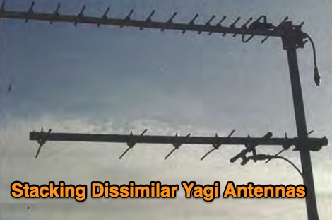 In this article the author provides some guidelines on how to solve a common problem when stacking different types of yagi antennas on the same mast, limiting the effects on gain and radiation pattern of both antennas
 -
 The NB6Zep Antenna, an electrically shortened 80-meter end-fed wire, addresses space constraints for low-band operation by integrating two loading coils into a 37-foot wire. This design, modeled with _EZNEC_, explores configurations like the quarter-wave sloper and inverted-L, with the latter providing a more vertical radiation pattern and practical backyard deployment. The resource details specific coil construction, recommending 21 uH coils made from _BW coil stock #3026_ or similar, and outlines wire segment lengths for optimal tuning. Performance analysis indicates a radiating efficiency of approximately 27% with good ground conductivity, resulting in a signal typically 3-4 dB down compared to a full-size quarter-wave vertical. The antenna exhibits a narrow bandwidth, around 50 kHz, due to its high Q, necessitating a tuner for broader band operation. Feedpoint impedance is low, with ground resistance playing a critical role in achieving a usable SWR. The article emphasizes the importance of an effective ground rod at the feedpoint for proper operation and tuning, suggesting an antenna analyzer for precise adjustments. It confirms the antenna's suitability for DX, citing successful contacts from Oregon to the East Coast and Hawaii on a 160-meter variant, making it a viable option for urban operators seeking low-angle radiation on 80 meters.
 -
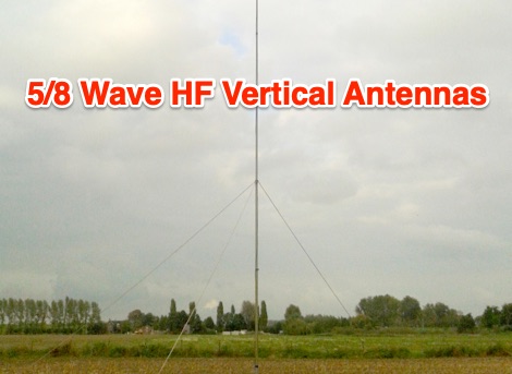 The advantage of 5/8 wave antenna is that it has the lowest angle of radiation and has about 1dB more gain when compared to 1/4 and 1/2 verticals. So the 5/8 should be the favourite choice for DX.
 -
 A vertical antenna project for the 7MHz made with some spare parts. Based on a broken 20 foot fishing pole, it is based on a good ground system made with radials and a capacitive hat done to increase the global radiation resistance of the antenna. A custom loading coil is also included in this project to perfectly tune the antenna to the CW portion of the 40 meters band.
 -
 The **Solarcon A99** vertical antenna, a half-wave over a quarter-wave variable mutual inductance design, primarily serves the 11-meter CB band but also finds use on 10 and 12 meters for amateur radio operators. Its simple construction, consisting of three fiberglass sections and a 16 AWG radiating element, makes it an accessible option for new operators or those seeking an easy-to-install base station antenna without complex mounting requirements. Despite claims of 9.9 dBi gain being widely considered exaggerated, and a manufacturer rating of 2000 watts power handling often viewed with skepticism (with 300 watts suggested as a practical limit), the A99 maintains popularity due to its low cost and ease of deployment. It typically tunes to a 1.2-1.3 SWR out of the box, requiring minimal adjustment via its two tuning rings. Its high angle of radiation allows for effective local communication even when mounted at low heights, such as 8-10 feet off the ground. However, the A99 is known for significant RF bleed-over issues, particularly when operated with higher power or mounted close to residential electronics. While its internal design is often described as cheap, the antenna exhibits remarkable durability, frequently lasting a decade or more in various weather conditions. Its affordability and straightforward setup continue to make it a go-to choice for many radio enthusiasts.
 -
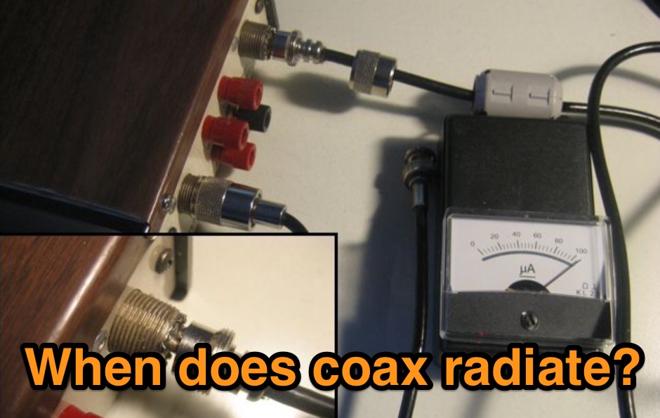 There are several reasons that can cause coax line radiation, most of them are related to wrong or missing use of a balun, but none can be imputed to load mismatch.
 -
 NVIS antennas, also known as Near Incident Vertical Skywave antennas have a high angle of radiation. Something on the order of 60 degrees, to straight up to 90 degrees. A portable, easy to setup and cheap nvis antenna project.
 -
 The current, the voltage, the impedance, the bandwidth, the polarization, and how the earth influences the famous radiation pattern.
 -
 "Instruments & Systems for Weather & Water Monitoring; weather stations, wind alarms, sensors for wind speed, wind direction, precipitation, temperature, relative humidity, barometric pressure, solar radiation, evaporation, rain & snow gauges, lightning detection."
 -
 ARRL page dedicated to RF Safety
 -
 Constructing a compact directional antenna for the 17-meter band, this resource details the build process for a Moxon rectangle, a two-element Yagi variant with folded-back elements. It covers the antenna's evolution from the _VK2ABQ beam_ and provides specific dimensions for a version built using fishing pole whips. The content includes a discussion of the antenna's radiation pattern, feedpoint impedance, and its inherent front-to-back ratio, which is often superior to a standard two-element Yagi. Practical considerations for element spacing and material choices are also addressed, alongside a visual representation of the antenna's physical layout. Performance data presented includes a comparison showing the Moxon rectangle's **2.5 dB gain** over a half-wave dipole and a front-to-back ratio of **20 dB**. The resource also touches upon the antenna's relatively wide bandwidth for a two-element beam and its suitability for portable operations due to its compact footprint. It offers insights into optimizing the design for specific operating conditions and discusses the advantages of its lower take-off angle compared to omnidirectional wire antennas, making it effective for DX contacts on the 17-meter band.
 -
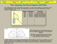 The radiating part is the vertical half of the dipole. You get nearly radiation in all directions, the second half must not be in 180°. The table below show how we get an impedance for direct feeding of 50Ohm coax. by DK7ZB
 -
 Understanding and using antenna radiation patterns
 -
 A monoband delta loop antenna for the 7 MHz. This vertically polarized DX Antenna is a full wavelength sngle side antenna and has a total length of 42.3 meters (137,1 inch) Can be easily setup with a flag pole or fishing pole as center top mast. For optimal performance lower side should be at 2 meter above the ground. This antenna offers a low radiation angle and 1 DB Gain.
 -
 Electric Fields, magnetic fields, electromagnetic fields, losses, fresnel zone, nearfield and farfield
 -
 Article on antenna feed impedance and the importance of matching RF andtennas to feeders, including notes on Radiation resistance, loss resistance, and efficiency are also detailed.
 -

-
 An article describing basic concepts of antenna radiation, and in particular directional antennas like Yagi antennas or Quad antennas and how they determine the direction or signals.
 -
 Preprinted from the 1997 ARRL Handbook for Radio Amateurs. Thermal Effects of RF Energy, Safe Exposure Levels, Cardiac Pacemakers and RF Safety, Determining RF Power Density
 -
 AN-SOF is a professional comprehensive software tool for the modeling and simulation of antenna systems. AS-SOF allows to describe antenna geometry, Choose construction materials, Describe the environment and ground conditions, Describe the antenna height above ground, Analize radiation pattern and front-to-back ratio, Plot directivity and gain, Analize input impedance and VSWR,Predict antenna bandwidth
 -
 The branch of electronics dealing with devices that generate, transform, transmit, or sense optical, infrared, or ultraviolet radiation
 -
 Make them simple then Make them work. The LAZY H antenna is a general type of antenna that is in the curtain array family. By placing two 1 wavelength dipoles in a plane that is at right angles to the direction of maximum radiation and keeping the proper in-phase current condition to each element, you can achieve a high gain bi-directional antenna.
 -
 The Tri-pole antenna, a clever modification of a standard dipole, allows for dual-band operation by integrating a third element. This design effectively shortens the overall dipole length by 10 to 20 percent, simplifying antenna rotation and offering a compact footprint. KK4OBI's article delves into the operational principles, using a 6 and 10-meter Tri-pole as a primary example, and provides comprehensive instructions for constructing any Tri-pole antenna within the 6 to 15-meter range. Key to the Tri-pole's performance is its off-center feed, necessitating a common mode choke at the feed point for optimal tuning and reduced noise. The author outlines a methodical approach to determining element dimensions, starting with a vertical element frequency calculated as 0.47 times the sum of the desired upper and lower band frequencies. This calculation, along with K-values derived from trend lines, guides the initial lengths for the horizontal arms, demonstrating how a 10m-6m Tri-pole can achieve a total horizontal length 78% shorter than a conventional 10-meter dipole. Tuning and balancing are critical, with the article detailing adjustments to arm lengths and the vertical element to achieve balanced SWR values, as validated through 4NEC2 simulations. Radiation patterns are analyzed at various elevations, showing gains around 5.7 dBi and favorable take-off angles for DX contacts. Construction details specify aluminum tubing dimensions, U-bolts, and an SO-239 connector, emphasizing the importance of a ferrite-based choke for wideband operation.
 -
 This page delves into the Inverted V antenna, a source of myths among ham radio operators. The author explores the behavior of this antenna type with a focus on a 20m half-wave dipole positioned 10m above the ground. From Pythagoras to high school math, the article simplifies the calculation of dimensions and angles for setting up an Inverted V antenna. It includes a spreadsheet for calculating hypotenuse length and angles, crucial for antenna setup. Additionally, it provides insight into the radiation pattern of a 'flat' half-wave dipole at 10m height. Useful for hams planning to optimize their antenna setup. In Norwegian.
 -
 Constructing a dual-band antenna for 40 and 20 meters often involves compromises in size or complexity. This resource presents a compact _open sleeve dipole_ design that addresses these challenges by using 450-ohm ladder line and folded elements to achieve a total length of approximately **17.17 meters**, significantly shorter than a full-size 40-meter dipole. The design leverages electromagnetic coupling, where a primary radiator handles the 40-meter band, and a second conductor resonates on 20 meters without direct electrical connection. This configuration eliminates the need for traditional traps, loading coils, or switching components, simplifying construction and reducing potential loss points. The antenna is fed with RG-58C/U coaxial cable, and a common-mode choke is recommended at the feed point to suppress sheath currents, ensuring a cleaner radiation pattern and minimizing RF in the shack. The design is well-suited for portable operations, field deployments, temporary installations, and restricted urban environments where space is a premium, offering solid performance on both HF bands.
 -
 Construction tips of a basic wire antenna, the half wave dipole. Inverted V dipoles and effects of inverted v on radiation pattern.
 -
 F5NPV introduces a variant of the W8JK antenna design, employing the MOXON principle. With extended monopoles, it outperforms the Open-Folded W8JK, yielding a 1dbd gain improvement, enhanced performance on 30m and 10m bands, bi-directionality, and lower side attenuation. The design's focus on higher radiation impedance results in increased antenna efficiency and reduced losses. Despite these improvements, the bill of materials remains unchanged.
 -
 2 Wavelength ,2 Meter Bi-Square Beam , 5dbd gain. This antennas are very cheeap to build and their radiation pattern is similar to a figure 8 with maximum signal through the loop but they may be used as a near-omnidirectional antenna
 -
 The title may seem a strange question. Still, it is often said that the part where the current is largest, radiates most. And from that a rule of thumb follows, saying that if you don't have enough space to hang a complete half-wave wire dipole then try to make the central part hang as freely as possible.
 -
 This page by Keith Greiner describes a magnetic loop antenna project, providing step-by-step instructions to create two versions of a system with one large loop and one small loop. It includes details on how to construct the loops using different materials, along with the necessary equipment like antenna analyzers, tuners, and software. The page is divided into five sections covering project discussion, design summary, an improved small loop, construction steps, and radiation pattern analysis. Aimed at hams interested in building their own magnetic loop antennas, the page offers practical guidance and insights into impedance matching for improved performance.
 -
 The _G3TSO_ Mobile Antenna Page details construction and tuning methods for mobile antennas operating across **10 to 160 metres**. The content describes a Hustler-based design, optimized for RF performance and vehicle speeds, featuring centre loading. For optimal operation on various bands, the loading coil placement requires clearance from the vehicle body. Antenna resonance is critical for efficient mobile operation. A mobile antenna's base impedance may be as low as 27 ohms, requiring specific matching to achieve maximum radiation, as a minimum SWR at the transmitter does not always indicate resonance or maximum output. Tuning involves physical adjustment of antenna length to achieve resonance at the operating frequency. The _G3TSO_ page outlines a tuning procedure utilizing a low-power signal source and a field strength meter to identify maximum radiation before impedance matching. Loading coil placement, either at the base, center, or top of the antenna, influences radiation efficiency and mechanical stability for mobile installations. Centre-loaded whips, such as the Hustler design, offer a compromise between efficiency and stability, often for single-band operation. Helically wound antennas, including those for **28 MHz**, may present base impedances around 17 ohms, resulting in a 3:1 SWR at resonance. Low resistance grounding at the antenna base is also specified for optimizing performance and minimizing RFI during mobile operation. DXZone Focus: Mobile | Any | Antenna Tuning | HF
 -
 The HB9CV antenna calculator aids amateur radio enthusiasts in designing antennas for VHF and UHF bands. By inputting the working frequency, users can obtain crucial dimensions like dipole lengths and distances. The tool, based on the HFSS antenna model, provides data on impedance, VSWR, and gain, optimizing front/back radiation ratios. It includes tips for fine-tuning using a Г-matching balun and compensating capacitor, ensuring effective performance and minimal VSWR for enhanced radio communications and direction finding.
 -
 Steve Nichols, G0KYA, presents a practical examination of ground systems for vertical antennas, drawing heavily on the empirical research of Rudy Severns, N6LF. He explains that a robust radial field is crucial for ground-dependent verticals, effectively replacing the antenna's "missing half" and mitigating severe RF absorption in lossy soil. Nichols clarifies that surface radials do not strictly require a quarter-wavelength; instead, deploying a minimum of 16 to 32 shorter wires often yields superior results compared to fewer, longer ones. The presentation also addresses the common SWR paradox: a poor ground might show a perfect 1:1 match, but adding radials, while potentially raising the SWR to around 1.4:1, significantly improves true radiation efficiency. Nichols defines counterpoises as elevated wire networks that substitute for earth connections, offering solutions for limited-space installations, such as the **Folded Counterpoise (FCP)** for 160 meters. This resource provides actionable engineering data for optimizing vertical antenna performance.
 -
 This project introduces the SN 1/8 mobile antenna, a compact and mechanically stable alternative to traditional 1/41/4 or 5/85/8 wave antennas. Designed for VHF/UHF mobile communications, this 20 cm antenna offers superior performance in moving environments. Its spherical radiation pattern enhances reflections, providing a 2 dB gain. Ideal for vehicle use, it is discreet, easy to install, and resistant to vibrations, making it a practical choice for mobile users seeking reliable and efficient communication. In French.
 -
 This article explores the conventional wisdom about antenna height in amateur radio operations, challenging the common belief that "higher is always better." Through practical examples and computer modeling, it examines how low-height antennas like Beverage antennas, VP2E, and End-Fed Half Wave (EFHW) configurations can perform effectively in various scenarios. The analysis includes radiation patterns and efficiency considerations for antennas at different heights, particularly focusing on portable operations. The article demonstrates that while height affects antenna performance, lower installations can still provide practical and efficient solutions for specific applications, especially in portable and QRP operations.
 -
 Discussion about the Standard Horizontal, Center-fed dipole and effects of elevation of the antenna on antenna radiation pattern.
 -
 This project explores the construction and performance of an Alford Loop antenna as an alternative to a round loop. The Alford Loop, symmetrically fed at opposite corners, behaves like a small loop despite its larger size. Built using PVC pipes and secured with tire wraps, the antenna integrates an LZ1AQ active amplifier for optimal performance. With deep nulls in its horizontal radiation pattern and improved resonance characteristics, this design has significantly outperformed previous active antennas in reception quality.
 -
 This project details the construction of a compact, circularly polarized Quadrifilar Helix Antenna (QHA) designed for 146 MHz operation. The antenna features a 1/2λ1/2λ helical design with a 2.6:1 aspect ratio, providing 4.5 dB gain and a spheroid radiation pattern. It is ground plane independent and compatible with both vertical and horizontal polarizations, making it ideal for terrestrial and space communications. The design includes step-by-step instructions for building the antenna using readily available materials like aluminum rods, PVC pipes, and RG-58 coaxial cable. The antenna's performance has been validated through comparisons with commercial omnidirectional antennas, showing superior results.
 -
 The article describes the construction of a Lindenblad antenna, which is well-suited for receiving signals from low-orbiting weather satellites. The key points are: The Lindenblad antenna has an omnidirectional horizontal radiation pattern and is optimized for low to medium elevation angles, making it ideal for tracking passing satellites near the horizon. It is designed to receive circular polarization, which is common for weather satellite signals. The antenna is constructed using 4 folded dipole elements arranged on a cross-shaped frame. The necessary materials include a plastic junction box, PVC tubing, and aluminum rods to form the dipole elements. The article provides detailed instructions for preparing the components, assembling the dipoles, and connecting the feed lines to create the complete antenna. The completed antenna can be mounted on a vertical support, with the dipole elements angled at 30 degrees from horizontal, to optimize reception of the passing satellites. The author notes that the design was originally published in a now-defunct magazine, Meteo Satellite Inf", in 1993
 -
 The multiband tuned doublet, or center-fed Zepp, is a simple and efficient HF antenna that operates effectively across most amateur bands using a balanced parallel-wire feedline and antenna tuner. Unlike coax-fed dipoles, it tolerates impedance mismatches with minimal loss. By selecting suitable feedline and dipole lengths, one can achieve stable multi-band operation. While it doesn’t match monoband Yagis, it offers excellent performance, low cost, and broad coverage. Its radiation pattern and efficiency vary with frequency, but it remains a practical and versatile solution for HF operators.
 -
 This page provides information on designing a lightweight Moxon antenna for the upper HF bands and VHF. The Moxon antenna is a compact version of a 2-element Yagi with folded elements, offering good forward gain and a high front-to-back ratio. It is designed for a single band with a feed-point impedance close to 50 ohms. Hams can orient the antenna horizontally or vertically, with polarization following the configuration, affecting radiation patterns. The page allows users to generate radiation pattern plots, VSWR charts, antenna currents diagrams, and Smith charts for their antennas on different ground types, helping them understand antenna performance in the field.
 -
 This page allows hams to design a vertical-plane delta-loop antenna for a single amateur HF band in different configurations. By choosing different feed-point positions, operators can observe variations in polarization properties, radiation patterns, and feed-point impedances. Users can generate radiation pattern plots, VSWR charts, antenna current diagrams, and Smith charts for their antennas over various ground types. Through adjusting the antenna's physical dimensions and refreshing the plots, hams can gain insights into the antenna's performance in the field. The page also discusses how elevation radiation patterns may change based on the antenna configuration and feed-point position.