Search results
Query: vertical antennas
Links: 183 | Categories: 14
Categories
- Antennas > 20M > 20 meter Vertical Antennas
- Antennas > 40M > 40 meter Vertical Antennas
- Manufacturers > Antennas > VHF UHF Microwave > Vertical Antennas
- Manufacturers > Antennas > HF > Vertical Antennas
- Shopping and Services > Antennas
- Radio Equipment > HF Vertical Antenna
- Antennas > Vertical
- Antennas > 160M
- Antennas > 20M
- Antennas > 40M
- Antennas > Dipole
- Radio Equipment > HF Vertical Antenna > GAP Titan
- Manufacturers > Antennas > HF
- Antennas > NVIS
-
 A vertical dipole for 10, 15, 20 and 40 meters made adapting two Hustler Model 6-BTV antennas by w6sdo
 -
 This resource details the conversion of an 80m elevated vertical antenna to include 160m operation, focusing on a relay-switched design over a trap-based approach. It presents specific feedpoint impedance values, such as **32 ohms** for 80m and **14 ohms** for 160m, and discusses the challenges of SWR drift encountered with the prior trap system during RTTY contesting. The article thoroughly explains the design choices for elevated radials, referencing _N6LF QEX data_ to debunk common myths regarding radial length and height, demonstrating that non-resonant radials can offer superior current uniformity. The construction section provides practical insights into building the vertical, including guying strategies, material selection from scrap pipe, and weatherproofing the relay assembly. It highlights the use of a common mode choke for the relay switching line, measuring approximately 5K ohms on both 160m and 80m, and details the L/C matching network's role in achieving a 50-ohm match at the end of a 300-foot RG-11 run. The author describes a precise VNA-based radial trimming procedure, achieving resonant values within a 3 KHz range. The content emphasizes the practical application of theoretical antenna principles, particularly concerning the interaction between the vertical element, cap hats, and the matching network. It offers a candid assessment of component selection, such as using junkbox parts and acknowledging the need for future upgrades to static drain resistors. The article serves as a comprehensive case study for advanced antenna builders tackling multi-band vertical designs.
 -
 A simple quarter-wave length vertical for 40m band using a 12 m spiderpole
 -
 Many antennas function because of common mode currents, rather than working in spite of them. Two popular examples are CFA and EH antennas. Another recent example, appearing in Antennex's compact antenna articles, is a thick stub "vertical" with no counterpoise.
 -
-
 Demonstrates the product line of _LZ Antenna Ltd._, a Bulgarian manufacturer specializing in amateur radio antennas and custom electronic devices. The company focuses on robust, high-quality HF multiband Yagi and vertical antennas, leveraging over 20 years of experience from founder Georgi Georgiev in radio amateur development. Featured models include the LZA 8-4, LZA-10-3, and the LZA-7-3A WRTC 2022, alongside various rotary dipoles like the LZA1 40/30m. Provides specifications for several Yagi antennas, such as the LZA-9-5, LZA-13-7, and LZA-6-3 (a 6-element, 3-band design). The company emphasizes applying "leading edge technology" to high-frequency communication equipment production, with products designed for durability and performance. The LZA-10-5 Yagi offers **12.5 dBi** gain on 10m, while the LZA-13-7 provides **13.2 dBi** on 20m, showcasing competitive gain figures for DXing and contesting.
 -
 By Guy, de ON6MU, At VHF, both the 1/4-wavelength monopole and the 5/8-wavelength monopole antennas are widely used.
 -
 NEC4WIN is a 32 bits commercial antenna simulation software based on MININEC3 developed by the Naval Ocean Systems Center in the 70s and 80s. It runs under Windows and can be used to simulate, analyze and optimize wire antennas, beams, verticals, etc. NEC4WIN has limitations. They are the same as Mininec3 on which the engine is based.
 -
 There is considerable confusion as to what exactly a multiband vertical antenna is. The confusion concerns the method of feed, how much mismatch one can expect, how many radials are required, how the particular antenna is built for multiband use, plus some other points.
 -
 The array consists of 7 vertical antennas arranged as 6 verticals in a hexagon shape plus 1 additional vertical in the center of the hexagon
 -
 GW4ALG's _136 kHz Pages_ document the evolution of vertical antennas for the 2200m band, starting with a prototype mounted on a house wall. This initial design, despite achieving the first **395 km** GM-GW QSO, suffered from significant insulation breakdown, high RF losses due to proximity to the house, and difficult tuning adjustments. The author details the challenges of maintaining resonance and matching with a variometer in the loft, noting that adding three earth spikes offered no measurable improvement over a simple water tap connection. The subsequent experimental 12m vertical, relocated away from the house, significantly reduced dielectric losses and proved far more effective. This antenna enabled GW4ALG to set a world DX record on 136 kHz with a **1916 km** QSO to OH1TN, and an intra-UK record of **703 km** to GM3YXM/P. The resource further explores the use of helium-filled balloons to extend the vertical radiator, achieving heights up to 27m, typically 20m, for enhanced low-band performance. Practical advice on balloon types, inflation, and critical insulation between the wire and balloon is provided, emphasizing safety and avoiding arcing.
 -
 Amateur Radio Station owned by Matt Strelow. The station is designed for competition in the multi-operator multi-transmitter category of high-frequency DX contests. Running with 7 towers 6 rotators, 8 beverage listening antennas, and 4 spotting verticals
 -
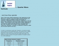 One of the most useful antennas in the repertoire is the Marconi or quarter wave grounded vertical antenna. Its invention made it possible to halve the length of antennas, simplifying communications, especially at HF and below.
 -
 Choosing a vertical antenna. Buying guide to amateur radio HF vertical antennas by Bencher inc
 -
 This article describes a project of asymmetrical hatted vertical dipole, a portable antenna that can be used for field day operations, sota, campings or even for fixed installations. This is a freestanding 20-10m antenna that is really easy to build, easy to tune and relatively easy to carry.
 -
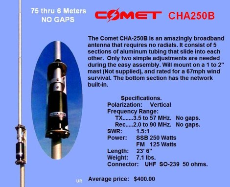 An interesting article by K3DAV comparing the COMET CHA250B to other HF multiband vertical antennas
 -
 Understanding Gain differences, j-pole and end-feed vertical antennas.
 -
 The G5RV multiband HF antenna, designed by Louis Varney (G5RV) in 1946, is a popular compromise antenna offering good overall performance on most HF bands when paired with an external antenna tuner. The basic full-size G5RV measures 102 feet across the top for 80 through 10 meter operation and is fed at the center via a 34-foot low-loss feed-stub. This interaction between the radiating section and the feed-stub facilitates matching across 80-10 meters with a standard tuner, often eliminating the need for ladder line directly to the shack. The antenna's design center frequency is 14.150 MHz, configured as a 3/2-wave dipole on 20 meters, with its 102-foot length derived from long-wire antenna formulas. Construction details emphasize the matching section, which can be open wire, ladder line (window-type), or TV twin lead. Each type has a specific velocity factor (VF) affecting its physical length for an electrical half-wave on 14 MHz; for instance, open wire requires 33.7 feet (VF 0.97), ladder line 31.3 feet (VF 0.90), and TV twin lead 28.5 feet (VF 0.82). The article provides formulas for calculating these lengths and discusses the antenna's behavior on individual bands, from 3.5 MHz where it acts as a shortened dipole, to 28 MHz where it functions as two three-half-wave long-wire antennas fed in-phase. Practical construction notes include recommendations for vertical descent of the matching section, sealing the coax junction, providing strain relief, and winding a coaxial choke coil to mitigate common mode current. The resource also presents dimensions for double-size (204 ft) and half-size (51 ft) G5RV versions, along with their corresponding matching section lengths for various line types, making it a versatile reference for hams considering this classic wire antenna.
 -
 A ATU for beam and vertical antennas by PA0FRI
 -
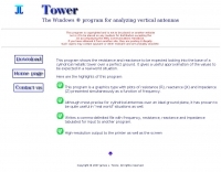 Windows program for analyzing vertical antennas. This program shows the resistance and reactance to be expected looking into a cylindrical metallic tower over a perfect ground. It gives a useful approximation of the values to be expected in a real-world situation.
 -
 The NCDXF/IARU International Beacon Project operates a worldwide network of 18 high-frequency radio beacons, continuously transmitting on 14.100, 18.110, 21.150, 24.930, and 28.200 MHz. These beacons, initially launched in 1979 with a single station and expanded to the current 18-beacon system in 1995, provide reliable signals for both amateur and commercial users to assess current **ionospheric propagation** conditions. The system's design, construction, and operation are managed by volunteers, covering hardware and shipping costs. The resource details the evolution of the beacon network, including the transition from Kenwood TS-50s transmitters to Icom IC-7200 radios with a new controller design implemented in 2015. It explains how listening for these 100-watt signals, transmitted to vertical antennas, allows operators to determine band openings and optimal propagation paths globally. The content also references three QST articles providing historical context and technical specifics of the beacon project. Practical information includes methods for identifying transmitting beacons via a schedule or specialized software like FAROS and Skimmer, which integrates with the **Reverse Beacon Network** for automated monitoring.
 -
 An off centre fed dipole, with 10 feet of vertical radiator. It needs no tuner on 40m, 20m and 10m by M0UKD
 -
 Deploying robust antenna infrastructure for both fixed and portable operations often requires specialized support structures capable of withstanding environmental stresses while providing optimal radiating element placement. SMC offers a range of solutions, including pneumatic masts and push-up masts, designed to facilitate rapid deployment and reliable long-term support for various antenna types. Their product line encompasses antenna mounts, poles, and complete antenna systems, addressing the critical need for stable and efficient RF communication. The company's offerings extend to HF antennas, including dipoles and _NVIS_ (Near Vertical Incidence Skywave) antennas, which are crucial for short-range regional communications on bands like 80m and 40m. These systems are engineered for durability and performance, ensuring signal integrity across diverse operating conditions. With over **65 years** of experience, SMC has established itself as a global manufacturer in this niche. Their product portfolio also includes antenna support towers, catering to more permanent installations requiring significant height and load capacity for multiple arrays.
 -
 A very efficient 80 meter Counterpoise antenna designed to reduce ground losses from inadequate radial systems beneath inverted L antennas, a project by DM2GM and DM4IM based on the original K2AV antenna concept.
 -
 The Gizmotchy high performance horizontal and vertical beam antenna for 2/6/10/11 meter bands
 -
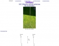
 This article compares two commercial vertical antennas for the 4-meter amateur radio band: the Watson WVB-70 half-wave and the Sirio CX4-71. The Watson measures 2.03m in length, costs around £40, and exhibited adequate performance but required additional waterproofing after rain affected its VSWR readings. The longer Sirio CX4-71 (3.02m) performed noticeably better, delivering signals approximately 2 S-points stronger than the Watson. The Sirio demonstrated high build quality, a stable 1.2-1.4:1 VSWR, and weather resilience, though minor VSWR fluctuations were observed during rain and frost. Both antennas are half-wave designs requiring no ground plane radials.
 -
 This resource details the four primary functions of a ground system: lightning energy dispersion, equipment safety, RF return path provision for end-fed antennas, and management of induced RF currents. It clarifies that a ground system's effectiveness varies depending on its specific function, noting that a good lightning ground might not be an effective RF ground. The content emphasizes that proper antenna system design, including baluns and appropriate feedline lengths, often negates the need for an RF station ground to mitigate common mode currents or RFI in the shack. The article quantifies lightning energy, stating its peak is in the dozens or hundreds of kilohertz, with damaging energy extending to hundreds of megahertz, and currents reaching thousands of amperes. It recommends solid, wide, smooth copper surfaces for ground leads to achieve low impedance across a wide frequency range. The author, W8JI, shares practical insights from his station, which includes two 300-ft towers and four 130-ft wire verticals, detailing his use of common point grounds and _DX Engineering RR-8 HD_ antenna switches for lightning protection without coaxial surge protectors. Specific examples of antenna systems prone to common mode current problems are listed, such as random wire antennas without proper feedline lengths and off-center fed dipoles. The text also explains how a ground screen or radial system can reduce local noise sensitivity for vertically polarized antennas by covering the lossy earth.
 -
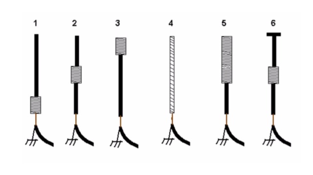 An interesting article on loading short vertical monopole antennas, representing six different methods. Base loading, Center Loading, Top Loading, Continuous loading, half and half loading and capacitive top loading.
 -
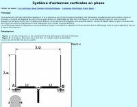
 Phased wire vertical antennas for 40 meters band
 -
 Ground Plane - 1/4 wave vertical, J-Pole, 3 Element Yagi Beam and simple antenna supports
 -
 The X80 multi-band HF vertical antenna, a commercial iteration of the Rybakov design, exhibits a physical length of 5.5 meters, or approximately 18 feet, and is constructed from aluminum tubing. It operates as a non-resonant vertical, requiring an external antenna tuner for impedance matching across its intended operating frequencies. The antenna's design incorporates a 1:4 UNUN at its base, facilitating a nominal 50-ohm feed point impedance for the coaxial cable. Performance observations indicate effective operation on 40 meters, 20 meters, 15 meters, and 10 meters, with reduced efficiency on 80 meters and 160 meters due to its relatively short electrical length for these lower bands. Comparative analysis with a G5RV dipole and a half-wave end-fed antenna reveals the X80 offers a lower take-off angle, beneficial for DX contacts, particularly on the higher HF bands. Field tests conducted with an Icom IC-706MKIIG transceiver and an LDG AT-100ProII autotuner demonstrate the X80's ability to achieve acceptable SWR across 80m through 10m. The antenna's compact footprint and ease of deployment make it suitable for restricted spaces or portable operations, though its performance on 80 meters is noted as a compromise compared to full-size resonant antennas.
 -
 A dipole antenna for 7 MHz support for this antenna is fiberglass military mast
 -
 Mounting on Roof or at Ground Level? Why ground plane antenna works better at lower level.
 -
 The collinear J-Pole, often known as the Super-J, does improve the behavior over a regular J-Pole. As many attest, there is an advantage when vertically combining 1/2 radiating sections to have a bit of separation between the half-wave end points. The Super-J has very little separation between the two half-wave radiators.
 -
 Butternut article on radials usage on vertical and ground plane antennas
 -
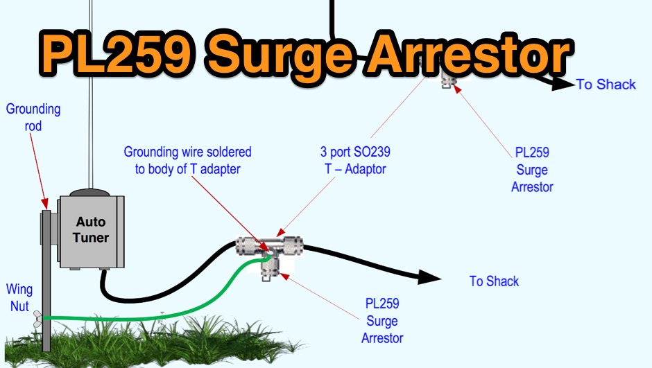 Limiting static surges on dipoles, verticals or end fed antennas
 -

-
 Modeling small 160 meter antennas, with a focus on the vertical H antenna
 -
 The vertical Double-Zepp 2x7 m is a very simple, effective 8-Band-antenna. The end of the Dipol must be 5-10 m above the ground
 -
 Hi-Z Antennas offers specialized high-impedance receiving systems, primarily focusing on phased vertical arrays for HF reception. Their product line includes preamplifiers designed for shortened vertical antennas, featuring optimized 15dB gain and array-matched characteristics. These components are engineered to enhance weak signal reception and improve signal-to-noise ratio across the HF spectrum. The company provides controllers for managing multiple vertical elements in a phased array configuration, enabling directional reception patterns. These systems are particularly effective for mitigating local noise and interference, a common challenge in urban and suburban operating environments. Specific offerings include solutions for 160-meter and 80-meter bands, addressing the unique requirements of low-band DXing. Technical details often reference components like the 2N3866 transistor in preamp designs and discuss concepts such as out-of-band attenuation. The focus remains on optimizing receiving antenna performance through impedance matching and active amplification, rather than transmit capabilities.
 -
 An comprehensive article on 40 meters antenna comparing vertical height to the resulting gain
 -
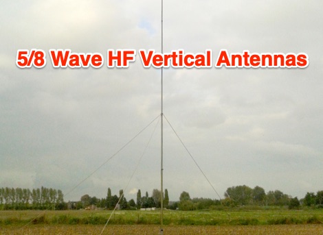 The advantage of 5/8 wave antenna is that it has the lowest angle of radiation and has about 1dB more gain when compared to 1/4 and 1/2 verticals. So the 5/8 should be the favourite choice for DX.
 -
 An excel spreadsheet that in a really simple way checks how much to trim your antenna elements. Download the xls file and watch the presentation video include in this page
 -
 Experimenting vertical wire antennas for 40 and 20 meters supported by balloons resulting in excellent gain in RX and good overall performance against horizontal dipole
 -
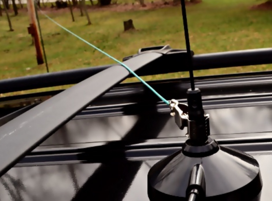
 Experiments on vertical antennas among the trees by ik2egl
 -
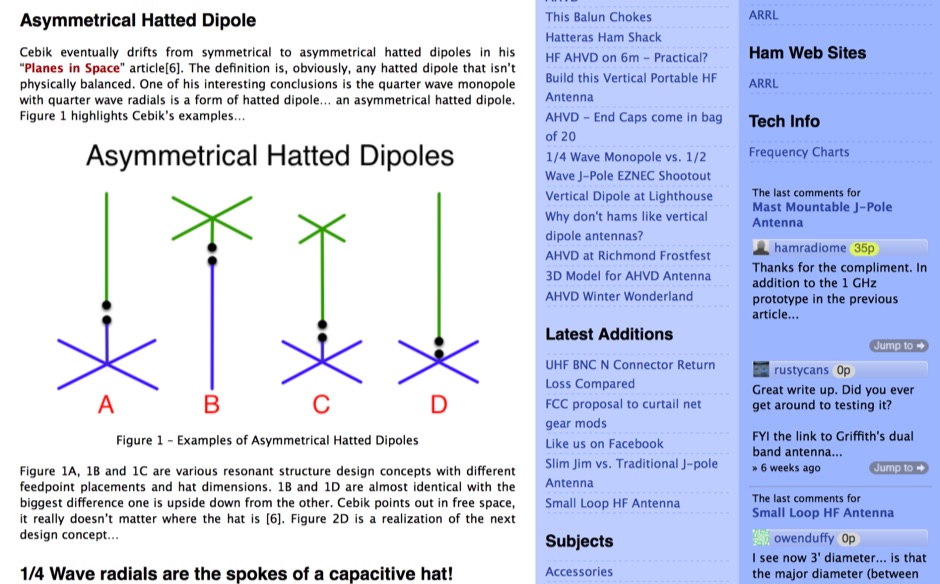 Theory and origins of W4RNL Asymmetrical Hatted Vertical Dipole AHVD for portable operations.
 -
 NVIS antennas, also known as Near Incident Vertical Skywave antennas have a high angle of radiation. Something on the order of 60 degrees, to straight up to 90 degrees. A portable, easy to setup and cheap nvis antenna project.
 -
 Amateur radio antennas manufacturer, produce multiband and monoband high performance yagi antennas and vertical antennas based in Poland
 -
 Ham Radio Vertical HF multiband antennas manufacturers based in Spain
 -
 Maltronix, HF antennas, dipoles and verticals, switching power supply, power distribution, antenna switch