Search results
Query: output
Links: 278 | Categories: 3
-
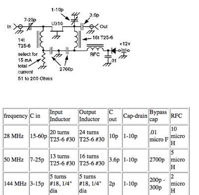 Extremely reliable FET preamplifier can handle several watts directly into either the input or the output without failure
 -
 1500 watts PEP output from a Kenwood TL-922 amplifier requires careful attention to parasitic suppression and component selection to ensure stability and longevity. This resource critically examines common modifications, often based on anecdotal evidence rather than sound engineering principles, that can degrade performance or introduce new issues. It highlights how replacing aged components often gets misattributed to the efficacy of unnecessary modifications, leading to widespread misinformation within the amateur radio community regarding amplifier stability. The article details specific, effective modifications for the TL-922, such as shortening anode-to-chassis and anode-to-grid paths to improve VHF stability and efficiency. It addresses issues like incorrect capacitor types in the tank circuit, inadequate grid grounding, and poor RF sheet metal design, providing practical solutions like adding direct ground connections for the plate tune variable capacitor. The author also discusses proper parasitic suppressor design, emphasizing the importance of lead length and component selection for optimal performance and harmonic suppression, contrasting these with less effective or detrimental 'magical suppression kits'.
 -
 A 50-ohm generator feeding a 50-ohm line connected to a _quarter-wave transformer_ (150 ohms) terminated in a 450-ohm load is analyzed to understand transient behavior. The paper meticulously tracks voltage and current waves, reflection coefficients, and power levels through a sequence of events, starting from quiescent conditions. It details how incident and reflected waves combine and interact at impedance discontinuities, illustrating the dynamic changes in impedance and SWR at various points in the system. The analysis reveals that the impedance at the interface between the 50-ohm line and the 150-ohm transformer changes from 150 ohms to **64.3 ohms** after the first reflected wave arrives. Subsequent reflections cause the impedance to asymptotically approach 50 ohms, reaching **53.22 ohms** after five wave terms. The study also examines the generator's reaction to transient SWR changes, noting that a 3:1 SWR can temporarily reduce generator output to 0.75 watts, but these effects are temporary and diminish as the system approaches steady-state conditions.
 -
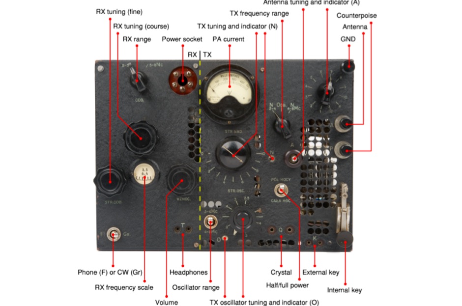 The BP-3 was a valve-based spy radio transceiver, developed during WWII by Tadeusz Heftman of the Polish Military Wireless Unit in Stanmore (UK). It was introduced in 1943 and was intended for use by Agents and Resistance Organisations in Europe. The transmitter produces an output power of 50 Watts in CW
 -
 Demonstrates the operational status and reception reports for the SK6RUD/SA6RR QRPP beacons, which transmit on 478.9 kHz, 1995 kHz, 10.131 MHz, and 40.673 MHz. These beacons utilize extremely low power, with the 630-meter beacon operating at approximately 0.1 watt ERP into an L-antenna, showcasing the potential for long-distance contacts under favorable propagation conditions. The site details the specific frequencies and antenna types employed, such as a vertical at 500 kHz and a 1/4 vertical for higher bands. The resource compiles over 10,530 reception reports from amateur radio operators worldwide, logging details such as date, time, band, RST signal report, locator, distance, and receiver setup. Notable long-distance reports include a 500 kHz reception by AA1A-Dave from 5832 km in 2008 and a 10.133 MHz reception by ZL2FT-Jason from 17680 km in 2010, illustrating the global reach of these low-power transmissions. Each log entry provides specific equipment used by the reporting station, including transceivers like the Yaesu FT817, ICOM IC-7300, and various antenna configurations such as coaxial mag loops, inverted Ls, and end-fed wires. The primary objective of the SK6RUD beacons is to challenge conventional notions of power requirements for effective two-way communication, proving that contacts over significant distances are achievable with minimal output. The site also includes a submission form for new reception reports, fostering community engagement and continuous data collection on propagation phenomena across different bands. The detailed logs offer practical insights into real-world propagation characteristics and the efficacy of QRPP operations.
 -
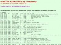 Presents a detailed compilation of **6-meter** voice repeaters operating within the 53-54 MHz segment across Australia (VK) and New Zealand (ZL), providing essential data for local and visiting radio amateurs. Each entry specifies the repeater's output and input frequencies, its assigned callsign (where applicable), the primary service area, current operational status (e.g., operational, under construction, scrapped), and a **Maidenhead grid locator**. The resource also includes the date the repeater was last heard or updated, offering insights into its recent activity. This listing is meticulously maintained by VK2KFJ, who updates entries based on personal observations and confirmed reports from other operators. It serves as a practical reference for hams seeking to utilize the 6-meter band for local communication via repeaters, particularly for those engaged in mobile or portable operations within the specified regions. The data helps operators configure their transceivers correctly for accessing these vital communication hubs. Beyond the repeater details, the page also notes common 6-meter FM voice simplex frequencies, such as the 52.525 MHz international call frequency, and lists historical packet simplex frequencies, though their current operational status is uncertain. This comprehensive approach ensures that operators have a broad overview of 6-meter activity in VK and ZL.
 -
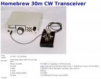 10.100 - 10.140 MHz 3 Watts output by 7n3wvm
 -
 A system designed to automatically tune small transmitting magnetic loop antennas, particularly beneficial for **contest operations** where rapid frequency changes are common. The core of the system involves a PC-based control application, AutoCap, written in C#, which monitors antenna SWR via an external meter and commands a motor interface to adjust the loop's variable capacitor. The software is compatible with Windows and Linux via the Mono framework, offering a graphical user interface for monitoring system status, SWR, power, and motor commands. Key components include one or more magnetic loop antennas equipped with DC or stepper motors for capacitor adjustment, an SWR meter with data output (such as the Telepost LP-100A or a homebrew serial/USB SWR meter), the AutoCap PC software, and a motor interface. The most effective motor interface utilizes an **Arduino-based controller** with custom firmware, providing precise control over both simple DC motors and stepper motors, and supporting features like motor braking for finer adjustments. The system allows for configurable SWR thresholds, pulse widths, and motor effort settings to optimize tuning speed and resolution. Optional radio integration provides frequency hints, enabling the algorithm to learn the relationship between motor actions and resonant frequency, thereby speeding up initial tuning responses. The software also supports antenna profiles, allowing operators to save and recall specific configurations for different loops, including accumulated frequency hint data.
 -
 Antenna tuners are crucial for matching the impedance of antennas to the 50 ohm output impedance of transmitters. The _LDG Z-11 Pro_ is an automatic antenna tuner designed to handle up to 125 watts, making it suitable for a wide range of amateur radio applications. Its compact form factor allows it to pair well with transceivers like the _FT-857D_, providing a portable solution for operators who frequently change locations or setups. The tuner covers the 80 through 6 meter bands, offering a broad impedance match capability. Although it struggles with some loads, it performs well with typical ham antennas, even managing to load an 80 meter dipole on 6 meters. One of the standout features of the _Z-11 Pro_ is its 8000 memory slots, which enable it to remember successful matches and quickly retune when revisiting frequencies. This memory function significantly reduces tuning time, often to less than half a second. The unit is well-constructed, with improved pushbuttons and a sturdy metal case that offers good shielding. However, users should be aware of potential RFI issues and the lack of a power switch, which requires disconnecting the power cord to turn off the unit completely. Overall, the _LDG Z-11 Pro_ is a user-friendly and cost-effective tuner, offering advanced features that enhance its utility in various amateur radio setups.
 -
 Sometimes we need a little more output filtering than traditional designs offer. Look at a new filter that can give you that extra boost. QST article by W3NQN
 -
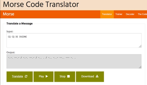 One hundred and fifty words per minute (WPM) is a configurable speed setting in this online Morse code translator, which facilitates bidirectional conversion between plain text and **Continuous Wave (CW)**. Users can input text to generate corresponding Morse code, or enter Morse code using dots and dashes to receive a text translation. The tool supports various alphabets, including Latin, Cyrillic, Ukrainian, Hebrew, and Arabic, broadening its utility for international communication. The platform offers multiple output methods for the generated Morse code, including audible playback, visual flashing, and device vibration. Advanced configuration options allow for precise control over the sound's pitch (frequency), volume, and overall speed, including a **Farnsworth speed** setting. This flexibility enables users to customize the learning or communication experience to their specific needs. Additional features include the ability to save the generated Morse code audio as a WAV file and to create shareable links for messages, which can be sent with or without the accompanying text. The interface is entirely web-based, built with HTML5 and JavaScript, ensuring broad compatibility across modern browsers.
 -
 Iphone App with list of nearby repeaters in the UK, along with details of input and output frequencies, a map, and a handy bearing arrow for each repeater.
 -
 Fixing the IC-7000 noisy audio that can occur when IC-7000 audio output is connected to Hi-Fi earphones or external speaker.
 -
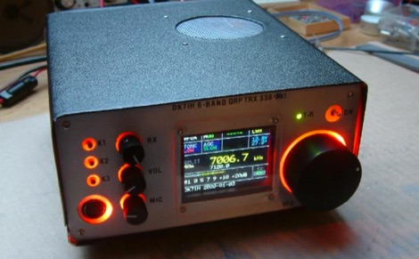 An SSB radio for the HF bands will be presented. Featuring 12 to 20 Watts of output power (depending on DC supply), full DDS frequency generation, covering 6 major frequency bands (1.8, 3.5, 7, 14, 21 and 28 MHz) within the short wave amateur radio spectrum. The rig also features colored LCD and front panel backlight.
 -
 100 W output RF amplifier for 10 meter band project by W4NFR
 -
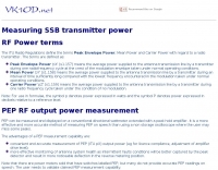 PEP RF output power measurement, and examples RF output power measurements
 -
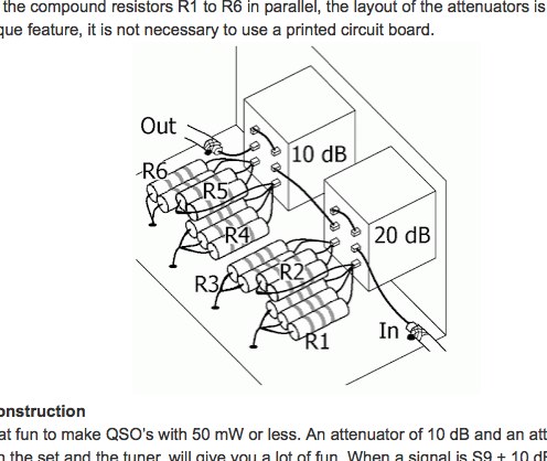 Attenuating output power to Yaesu FT-817 and interesting article for really QRP operations by PA1B
 -
 This project is an interface box for the Yaesu FT-817 that includes a band output port, a computer serial interface, and a remote interface for the FL-7000 solid state power amplifiers.
 -
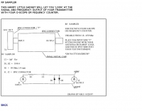 This circuit will let you look at the signal and frequency output of your transceiver.
 -
 Constructing a high-power 70cm solid-state amplifier presents unique challenges, particularly when aiming for 500 watts output using modern LDMOS devices. This resource details the author's experience building a 70cm amplifier based on a _Freescale MRFE6VP5600H_ transistor, initially from an RFHAM kit. It meticulously outlines the necessary modifications to achieve advertised performance, including optimizing input and output matching, correcting bias circuitry, and ensuring proper output balun connections for stability. The author shares specific adjustments, such as trimming the prototyping board for better transistor fit, drilling additional mounting holes for improved heat sinking, and replacing original matching capacitors with a single _20pf MIN02 metal mica_ for superior output. A critical fix involved jumpering gate decoupling pads to balance the push-pull transistor halves, which increased output to 580W and improved IMD. The resource also highlights a crucial correction to the output balun connection, initially reversed in the _Dubus_ article schematic, which resolved intermittent stability issues. Test results are provided, showing input power, output power, and drain current at 50V, demonstrating the amplifier's performance after modifications. This practical account offers valuable insights for hams undertaking similar high-power UHF amplifier projects, especially those working with LDMOS devices and kit-based constructions.
 -
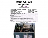 1500 watts of RF output on the 70cm band requires robust amplifier design, a challenge addressed by this project featuring the GS-23b / 4CX1600U Svetlana tube. The resource details the construction of a high-power UHF amplifier, providing insights into component selection and layout necessary for stable operation at these frequencies and power levels.
 -
 A DIY Automatic Band Decoder (ABD) project, designed for dual-radio operation, addresses the common challenge of integrating band data with older transceivers lacking dedicated outputs. This particular build utilizes an AVR AT90S8515 microcontroller and a 16x2 Liquid Crystal Display (LCD) to provide band information, specifically targeting Kenwood rigs via a computer's LPT port. The design aims for cost-effectiveness while maintaining functionality, offering a solution for hams seeking to add automatic band switching capabilities to their station without significant expense. The project outlines the core components required, including the microcontroller, LCD, and an enclosure, noting that the Printed Circuit Board (PCB) fabrication and AVR programming might present challenges for some builders. It details the input requirements, such as a four-pin input and PTT for each radio, along with a 13.8V DC power supply. The decoder provides 2x6 outputs capable of sinking 500mA, suitable for controlling external devices like antenna switches or filters. Despite the original unit being damaged by a lightning strike in 2004, the author confirms its successful operation prior to the incident and mentions plans for a revised version. The resource includes a schematic in PDF format and images of the finished PCB and assembled unit, demonstrating the practical implementation of the design.
 -
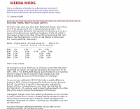 This is a collection of emails collected over time which indicate how to put some mods into your Sierra transceiver. Most of the mods have to do with improving the power output.
 -
 The m0xpd keyer project utilizes a PIC16F628A microcontroller, offering Iambic A and B modes, adjustable speed from 5 to 40 WPM, and variable weight control. It incorporates a sidetone generator with adjustable frequency and volume, along with a PTT output for transceiver control. The design includes a 16-pin DIL IC socket for the PIC, a 3.5mm stereo jack for the paddle, and a 3.5mm mono jack for the PTT output. Powering the keyer requires a 9V DC supply, which is regulated down to 5V for the PIC. The circuit board layout is designed for through-hole components, facilitating home construction. A detailed schematic and a parts list are provided, guiding builders through the assembly process. The project also discusses the firmware programming for the PIC16F628A, essential for the keyer's functionality. Construction details cover component placement and wiring, ensuring proper operation. The keyer's compact size makes it suitable for portable or shack use, providing a reliable CW interface.
 -
 This graphics-intensive program reveals the load on the output of a matching-network, based on measurements of the components in that network. Adjust the network (tuner) for a flat input, measure or look up the network component values and you will immmediately see the R and jX values of the load on the network, presented as both a schematic with the component values and as a Smith Chart normalized to the specified system impedance.
 -
 Accessing this interface provides entry to one of the largest databases for amateur radio voice repeaters, encompassing over 8000 entries from more than 60 countries. The resource supports both desktop and mobile access, with a default display based on browser type, or forced via a "force" parameter (e.g., relais.dl3el.de?force=mobile). Users input a QTH-locator to find local repeater information. The database integrates FM-Funknetz servers and hotspots, potentially creating duplicate entries but ensuring new FM-Funknetz repeaters are immediately displayed. DMR repeater information, including status and talkgroup configurations, is sourced directly from DMR+ / ircDDB and Brandmeister systems, with real-time updates for active and default talkgroups. C4FM/Wires-X installations, particularly MMDVM-based gateways not listed in Yaesu's database, are identified through Brandmeister dashboard descriptions, marked with "W-x" or "W-x#MMDVM" for manual entries. D-Star repeater data from ircddb or QuadNet2 is also incorporated, with entries marked (i), (o), or (d) for manual additions. An APRS interface allows searching by callsign, using Sassan, DL3NCK's database, and offers a mobile-friendly, auto-refreshing display that follows an APRS station. Output data can be generated in GPX format for offline smartphone maps or CSV for spreadsheet applications. The database also attempts to determine valid repeater offsets based on IARU region and frequency, indicated by a "." after the frequency.
 -
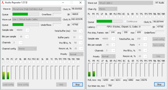 Audio Repeater is a windows application tha allows you to transfer, transmit, sounds from an input audio endpoint or device to an output one Playback. Audio transfer can be performed in any PCM audio format supported by Windows. KS version communicates directly with audio driver, bypassing all additional Windows audio processing
 -
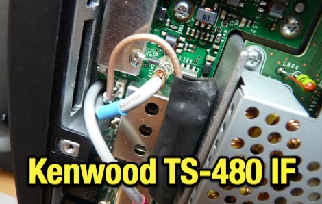 How to take the IF from a Kenwood TS-480
 -
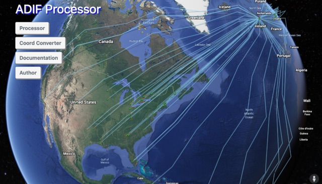 The ADIF Processor is an online application that visualizes amateur radio contacts from an ADIF log file using Google Earth. SOTA CSV log files can also be used. As well as allowing you to view and explore your contacts in Google Earth, you will be able to see a Markdown or text table of contacts, use the output ADIF file which contains QRZ.com data, accurate contact distances and fields populated from comments in the input file. Print QSL labels. One of the benefits of using the ADIF Processor before uploading/storing your ADIF file is detecting errors in callsigns and activity references (e.g. POTA or SOTA references).
 -
 Unfilter LF output from the TH215/415 kenwood portable radio
 -
 Designing a beacon keyer that transmit the relative output power along to call sign.
 -
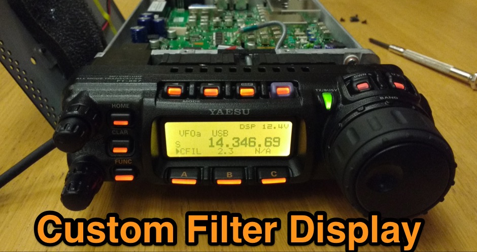 How to setup and install custom filters, usually inrad, into Yaesu FT 857 and FT 897 transceivers
 -
 A 600W 1.8 MHz to 54 MHz power linear amplifier made using rugged MRF300 transistors featuring output power between 580W and 750W depending on band, power supply: 48V, 18A typical, 20A max
 -
 Demonstrates the _RoMac Automatic CW Identifier 2012_ software, a Windows application designed to automate station identification and provide a tuning pulser. It can send CW identification via a sound card's audio output or by keying a radio's manual CW jack using a serial port's DTR line. The software also supports CAT commands for various Kenwood, Yaesu, Flex, and Elecraft radios, enabling automatic mode and frequency changes for ID transmission. It integrates with USB audio-capable radios like the Icom 7300 and Yaesu FT-991, simplifying connectivity with a single USB cable. The application features a fully programmable interface, adjustable CW speed from **5 to 35 WPM**, and ID intervals from **5 to 30 minutes**. The integrated "Pulse Tuner" function allows for safe amplifier and antenna tuner adjustments by sending short audio tones or rapid CW keying, with an adjustable duty cycle from 1% to 100%. It offers compatibility with a wide range of transceivers and amplifiers, and a schematic for a basic sound card interface is included for users without existing setups.
 -
 137.7 kHz QRSS beacon exciter is described, utilizing a single chip for operation on the 2200m amateur band. The design focuses on simplicity and efficiency for weak signal applications, providing a compact solution for generating QRSS signals. This project targets the DX portion of the band, enabling long-distance communication with minimal power output. The resource details the construction and functionality of the **QRSS beacon**, emphasizing its **low-power operation** and suitability for experimental amateur radio. It provides insights into the circuit's architecture and potential for integration into existing station setups. The design aims to offer a practical and accessible entry point for amateurs interested in weak signal modes on the LF/MF bands.
 -
 Generating clean PSK signals and helping others to correctly tune their souncard output, as well as giving proper RSQ reports by identifying signal quality by N1NKM.
 -
 A Linux Smith charting program. You can enter either discrete components or transmission lines, see the results on screen and/or generate Postscript output. Component values can be changed numerically or using scrollbar
 -
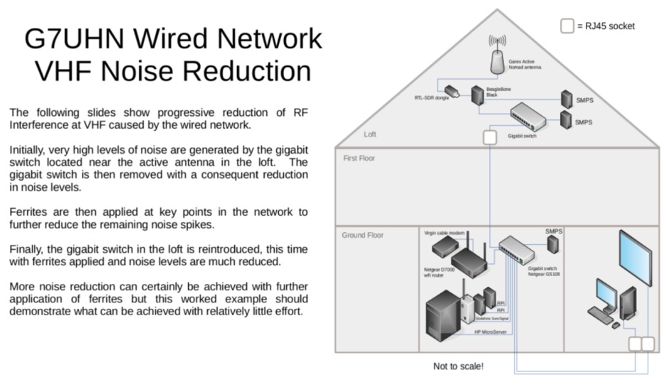 How to reduce and eliminate the RF interference at VHF caused by the wired network
 -
 A synthesized 2.3 GHz Amateur Television (ATV) transmitter design, conceived by Ian G6TVJ, is presented, targeting broadcast-quality video performance on the 13cm band and extending up to 2.6 GHz. The core of the design utilizes a commercial Z-comm Voltage Controlled Oscillator (VCO) that tunes from 2.2-2.7 GHz, providing a +10 dBm output and simplifying RF alignment. This VCO's stability, originally intended for narrowband applications, readily accepts high-frequency video modulation, contributing to the transmitter's robust performance. The exciter stage, incorporating a Mini Circuits VNA 25 MMIC amplifier, boosts the signal to +16dBm, while a Plessey SP4982 prescaler divides the output frequency for the synthesizer. The synthesizer employs a Motorola MC145151 CMOS parallel IC, favored over the common Plessey SP5060 for its superior video modulation characteristics and ease of programming without microprocessors. This choice addresses issues like LF tilt and distorted field syncs often seen with SP5060 designs, particularly when operating through repeaters or over long distances. The MC145151 divides the signal further, enabling precise frequency stepping, with programming handled by EPROMs for channel selection and LED display. The loop filter network, critical for video integrity, was developed through experimentation to prevent the PLL from reacting to video modulation, ensuring a clean transmitted picture. The transmitter incorporates a Down East Microwave commercial power amplifier module, delivering approximately 1.6W output, driven by the exciter through a 3dB attenuator. Construction involves surface-mount SHF components on micro-strip lines etched onto double-sided fiberglass board, housed within a tinplate box. The design boasts no AC coupling in the video path, preserving low-frequency response, a common failing in other ATV transmitters. Performance tests with a 50Hz square wave revealed no LF distortion, and a calibrated "Pulse & Bar" signal showed a near 100% HF response, demonstrating its capability for high-quality ATV transmissions.
 -
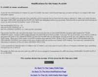 Adding a full power output 12 meter band capability to the Yaesu FL-2100 despite of 10 meter.
 -
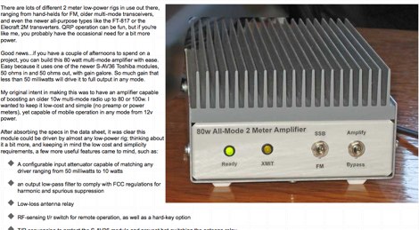 80 watt multi-mode amplifier using one of the newer S-AV36 Toshiba modules. Less than 50 milliwatts will drive it to full output in any mode.
 -
 A Short Guide to Harmonic Filters for QRP Transmitter Output. - George Dobbs G3RJV
 -
 Constructing a digital interface for the Elecraft K2 transceiver, this resource details the "Fat Wire" design by WG4S. It demonstrates how to integrate a sound card for digital modes, outlining specific connections to the K2's microphone jack and internal audio path. The author shares practical insights from his build, including the use of _RG-62_ coax for its flexible braid and the strategic placement of components like the 2.2K resistor and _2N2222_ transistor. The guide provides a breakdown of the interface's internal wiring, specifying connections for AF In (pin 1), AF Out (pin 5), PTT (pin 2), and Ground (pin 7) on the K2's microphone connector. It also covers the external connections to a laptop's headphone and line-in jacks, along with a DB-9 connector for PTT control via _DTR_ or RTS lines. The author notes that his laptop's headphone output level was sufficient for the K2, negating the need for an attenuator. Reflecting on the design, the author, Dan WG4S, acknowledges a later suggestion to house the components directly within the DB-9 shell for a more compact build. This iterative feedback highlights the ongoing evolution of DIY ham radio projects and the community's collaborative spirit in refining designs.
 -
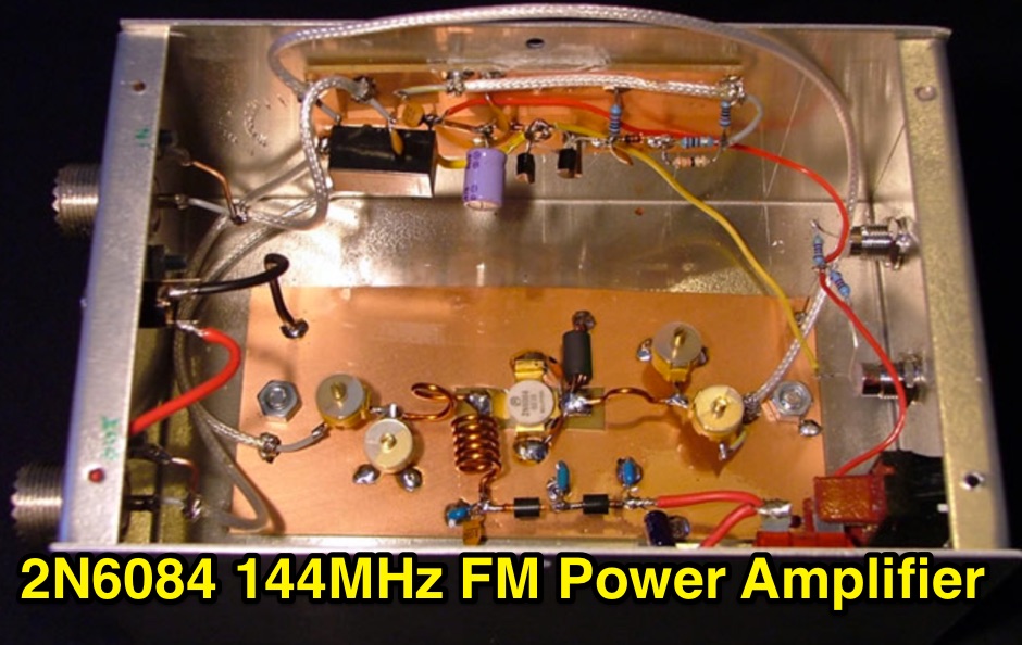 A 144MHz FM class C RF Power Amplifier based on a 2N6084 RF transistor, that can produce 50w output max
 -
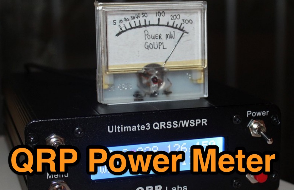 A really simple project to make a power meter measuring RF output powers from a few mW up to half a watt. A DIY amateur radio project for QRP enthusiasts
 -
 The AT-AUTO automatic antenna tuner handles 1.5kW CW operation, employing stepper motors under microprocessor control to precisely position a roller inductor and air-dielectric variable capacitor, avoiding relay-switched discrete components. This design choice prevents loud relay clacking and burning contacts, a common issue with competing products. The tuner features auto-retuning capabilities and receives periodic firmware updates, ensuring continuous improvement and added user-requested features. Its companion product, the _CX-AUTO_ coaxial switch, also features an embedded microprocessor controller. It enables selection of 1-of-8 coaxial outputs via a serial data interface. When integrated with the _AT-AUTO_, the tuner can associate specific coaxial outputs with amateur radio bands, automatically commanding the _CX-AUTO_ to select the correct antenna when the operator QSYs to a different band. Don Kessler began designing the AT-AUTO in 2005, with its debut at the 2006 Dayton Hamvention. Kessler Engineering also offers custom RF product design and electrical engineering consulting, specializing in Class-E RF amplifiers.
 -
 Makers of the The Polar Explorer transmitter, which operates on 9 HF bands from 160 through 10 meters and is capable of 500 watt peak output power on SSB, CW, AM, FM and RTTY. It is intended to be used in conjunction with a transceiver.
 -
 Measuring the output impedance (Zs) of solid-state broadband HF amplifiers operating in class AB eham article by ZS6BIM
 -
 The Kenwood TS-870S HF transceiver features two state-of-the-art 24-bit 20 MIPS DSP chips, providing over 100dB out-of-passband attenuation and CW bandwidth adjustable to 50 Hz. It operates across 160-10 meters with 100 watts output, incorporating digital filtering, a beat canceller, and 100 memory channels. The radio also includes a transmit equalizer, RX antenna input, and a K1 Logic Keyer, enhancing signal processing and operational flexibility for amateur radio operators. Advanced capabilities include IF stage DSP, dual noise reduction, and an auto notch filter, all contributing to superior signal reception and clarity. The TS-870S offers a variable AGC, voice equalizer, and an RS-232C port for computer control, with Windows™ software supplied. Its built-in automatic antenna tuner functions on all bands for both transmit and receive modes, streamlining station setup and operation. Available accessories such as the DRU-3A digital recording unit, SO-2 high stability crystal oscillator, and VS-2 voice synthesizer option further extend the transceiver's utility. The unit requires 13.8 VDC at 20.5 Amps and is supplied with an MC-43S hand microphone, making it a comprehensive station component.