Search results
Query: aris
Links: 174 | Categories: 11
Categories
- Radio Equipment > Reviews and Comparisons
- Radio Equipment > HF Amplifiers > Alpha 9500
- Radio Equipment > HF Portable Antenna > Buddipole
- Radio Equipment > HF Transceivers > Elecraft KX2
- Radio Equipment > Microphones > Heil PR-781
- Radio Equipment > HF Transceivers > Icom IC-703
- Radio Equipment > HF Transceivers > Icom IC-7600
- Radio Equipment > HF Transceivers > Icom IC-7851
- Operating Modes > International Space Station
- Radio Equipment > VHF-UHF Mobile > Kenwood TM-D710
- Antennas > ZS6BKW
-
 EA4EOZ details the construction and testing of 50 MHz traps, a critical component for multiband antenna designs. The project addresses the challenge of sourcing high-voltage capacitors suitable for trap applications, exploring alternatives to expensive doorknob capacitors. The author successfully fabricated a capacitor using 1.6mm double-sided FR-4 PCB material, achieving a capacitance density of **2.6 pF/cm2**. Utilizing the _VE6YP calculator_, specific L and C values of 30 pF and 0.31 uH were determined for a 2cm diameter coil. Both the FR-4 PCB trap and a coaxial cable trap, constructed from _RG-58_, were built and tuned to approximately 50 MHz using a spectrum analyzer. The coaxial cable trap demonstrated superior performance, exhibiting a notch nearly **20dB deeper** than the FR-4 version. This practical comparison provides insights into trap construction for experimental antennas, with the coaxial cable trap selected for an antenna project intended for operation at up to 100 watts.
 -
 N6CTA provides a comprehensive tutorial on manually configuring NTP synchronization for Debian Linux, ensuring accurate system time for FT8 and other amateur radio modes. The guide covers updating the system, installing and enabling NTP, verifying the timezone, and using the iputils-clockdiff tool for precise time comparison. A script is included to check and sync system time, enhancing the performance of synchronous modes like FT8.
 -
 Antennas for low-power operation resemble those for 100W use. Minor adjustments, like capacitor voltage ratings, may apply, but basic principles persist. Portable antennas, notably Backpack Antennas for weight-conscious setups, hold relevance beyond QRP. While some antennas function acceptably at higher power, efficiency issues arise at QRP levels. Testing antennas at 100W exposes weaknesses, particularly in tuners, crucial for efficient QRP operation.
 -
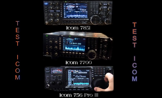 Reception test comparison between IC 756 pro III, IC 7700 and the last jewel by ICOM IC 7851
 -
 Chavdar Levkov, LZ1AQ, presents an experimental comparison of small wideband magnetic loops, building on his previous work on wideband active small magnetic loop antennas. His research focuses on increasing loop sensitivity by maximizing the short-circuit current, which is directly tied to the "loop factor" M = A/L, where A is the equivalent loop area and L is its inductance. Levkov's methodology involves reducing inductance and increasing area through parallel or coplanar crossed (CC) configurations, comparing these designs against a reference single quad loop of 1 m2 area. Experimental verification included testing three distinct loop types: a simple quad loop, two coplanar crossed (CC) loops, and eight parallel loops, all designed to have a total geometric area of 1 m2. Measurements were conducted at 1.8, 3.5, 7, and 10 MHz using a small transmitter 270 meters away, with a Perseus direct sampling receiver for precise signal level assessment. The results consistently showed that CC loops, particularly Loop 5 (two CC circular loops with 1.44 m2 total area), yielded significantly higher currents, up to 9.1 dB over the reference loop at 3.5 MHz, validating M as a reliable predictor of loop sensitivity. Numerical simulations using MMANA further corroborated the experimental findings, demonstrating an almost perfect correlation between the calculated M factor and the induced loop current for 15 different loop models. Levkov concludes that CC loops offer superior sensitivity for a given loop area, while parallel loops are advantageous for minimizing physical volume. Practical recommendations suggest using loops with an M factor greater than 0.5 uA/pT for quiet rural environments, and he provides a spreadsheet tool, WLoop_calc.xls, to aid in optimizing loop configurations for specific operational needs.
 -
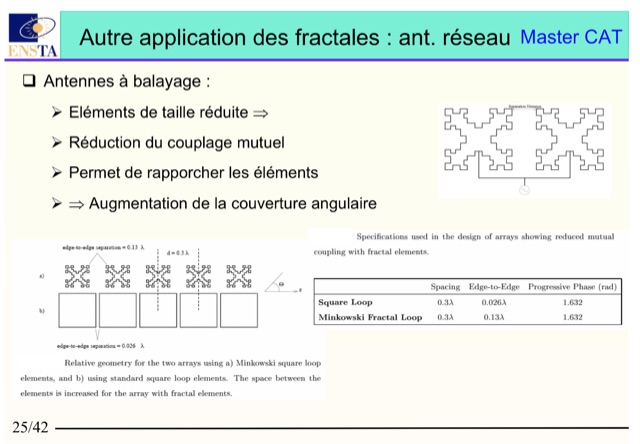 A course on fractals antennas theory provided by La Ecole nationale superieure de techniques avancees in France. Course is in French.
 -
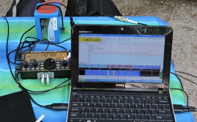 In this article, the current consumption for a selection of popular HF transceiver was examined to determine, via an on the field comparison, whether they were right for portable operation. The radios evaluated include the Yaesu FT-857D, Kenwood TS-590SG, Icom IC-7100, and Kenwood TS-480SAT. The measurements were taken beginning frok 5W in 5W increments up to 100W. The results showed that the Kenwood TS-590SG had the highest current use while the Yaesu FT-857D had the lowest. The current consumption of all radios increased as the power output increased.
 -
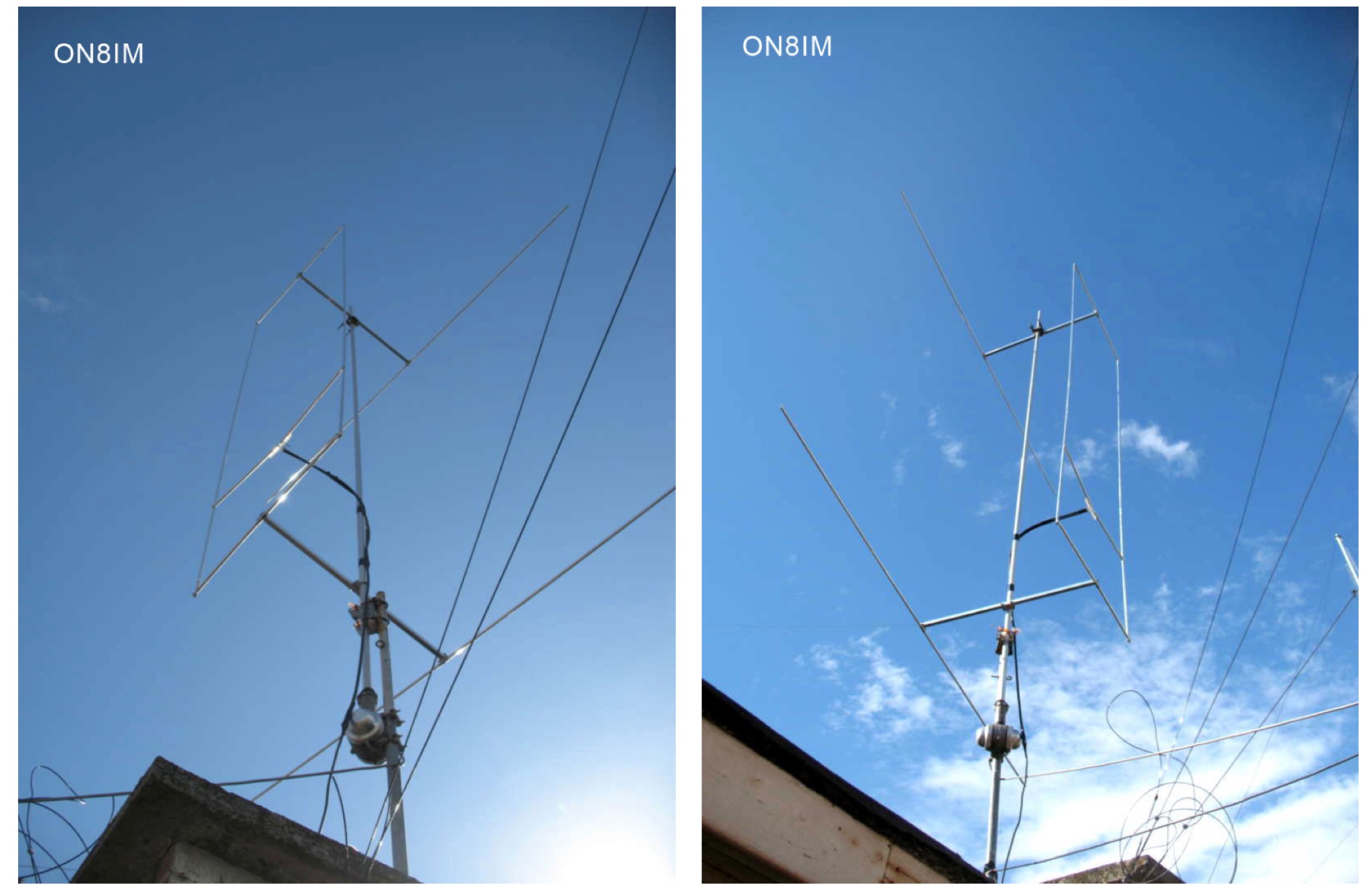 Explores the addition of a reflector to the traditional Hentenna design for 6m band, providing construction insights, performance comparisons, and modeling data
 -
 VE1ZAC's analysis details the performance of **MFJ927** and **SGC239** autotuners with portable HF vertical antennas, specifically comparing 31 ft and 43 ft configurations. The resource originated from challenges encountered during a Maritime QSO Party roving operation, necessitating a lightweight and easily deployable antenna system. Target bands for the contest included 80, 40, 20, 15, and 10 meters, with a maximum power handling of 100 W CW. The author utilized a 30-foot carbon fiber push-up pole to support a vertical wire element, noting its 2 lb weight and reliability. EZNEC modeling was employed to predict performance, showing favorable results for a 30-foot vertical with elevated radials, particularly on 40 and 20 meters. Feedpoint impedance measurements, taken with an AIM4170C, are presented for various HF bands, both with and without a 41-foot RG6 stub designed to reduce reactance on 80 and 20 meters. The stub significantly improved matching on these bands, easing the tuner's workload. Operational tests revealed issues with the MFJ927's reliability during contest setup, leading to reliance on the K3's internal tuner. The SGC239, tested post-contest, performed flawlessly. A detailed side-by-side comparison covers mechanical aspects, connection options, power bias, impedance range, board quality, and documentation. Modifications to the MFJ927, including a new aluminum case, white paint for heat reduction, and upgraded impedance-measuring resistors, are also described.
 -
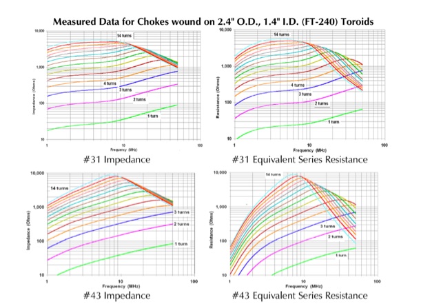 FT-240 toroids measurements. The data was measured using well-calibrated HP instrumentation. All plots have been adjusted to a frequency range of 1-100 MHz on the horizontal axis and a resistance/impedance range of 10-1,000 ohms on the vertical axis. This adjustment facilitates comparison among different materials and aids in determining their suitability for use on the HF ham bands.
 -
 Operating on the 60m band requires specialized antennas, and the 2 Element HB9CV, also known as the _ZL special_, excels in this domain. With a gain of **7.3 dBi** when phased at a 162-degree shift, it rivals traditional 3-element Yagi antennas, making it a solid option for enhancing 60m operations. The construction process is thoroughly detailed, providing insights into its performance and practical applications. Real-world comparisons demonstrate that the HB9CV antenna outperforms long Beverage antennas by an average of **5.5 dB** in reception, showcasing its effectiveness in various conditions. Insights from Mr. Cebik's analysis further validate its design, confirming its capability to maximize communication on the 60m band.
 -
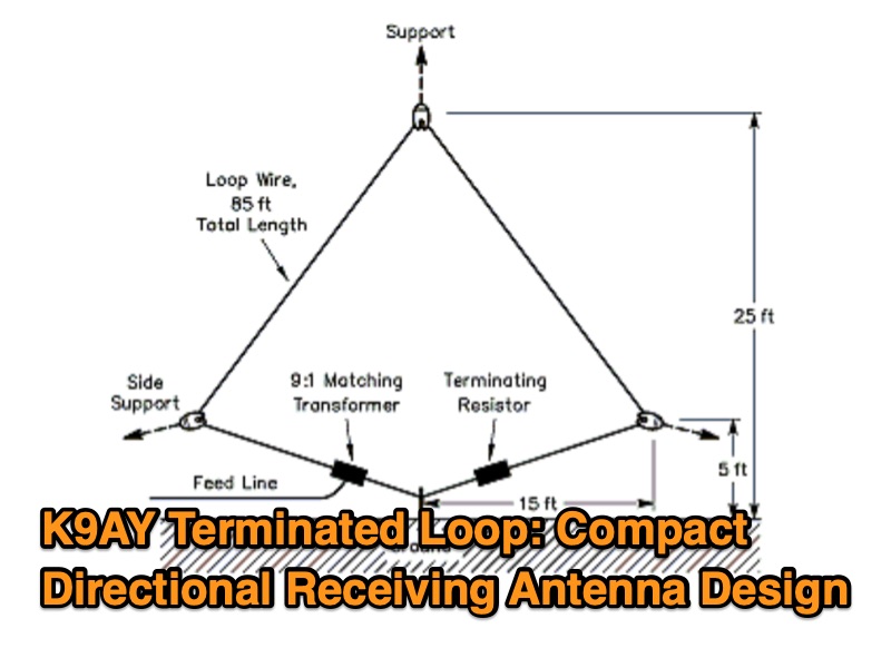 This resource presents the design and characteristics of the K9AY Terminated Loop, a compact directional receiving antenna system. The document details the antenna's physical and electrical configuration, consisting of a wire loop, a 9:1 impedance-matching transformer, and a terminating resistor. It describes how the antenna achieves directionality, favoring signals from the feed point end and rejecting signals from the terminating resistor end by several S units. The system is designed for low-band operation, specifically mentioning its application for improving reception on bands where space is a constraint. A four-direction system, utilizing two loops oriented at right angles with a relay-controlled switching system, is discussed. The resource includes a comparison of the K9AY loop's footprint to that of an equivalent EWE array, indicating the K9AY system requires approximately 1/7 the area while maintaining similar directional patterns. The design prioritizes signal collection sufficient for use with modest preamps, such as those integrated into HF transceivers. The article was originally published in QST in 1997.
 -
 The article explores the concepts of return loss, VSWR, and S11 within the context of microwave engineering, highlighting the confusion arising from their definitions. It clarifies that these parameters, while seemingly distinct, fundamentally describe the same phenomenon related to wave reflection and transmission in microwave circuits. The discussion emphasizes the historical context and mathematical relationships among these terms, revealing that their interpretation can vary significantly across different engineering disciplines. Ultimately, it advocates for a pragmatic approach to using these parameters based on familiarity rather than strict definitions.
 -
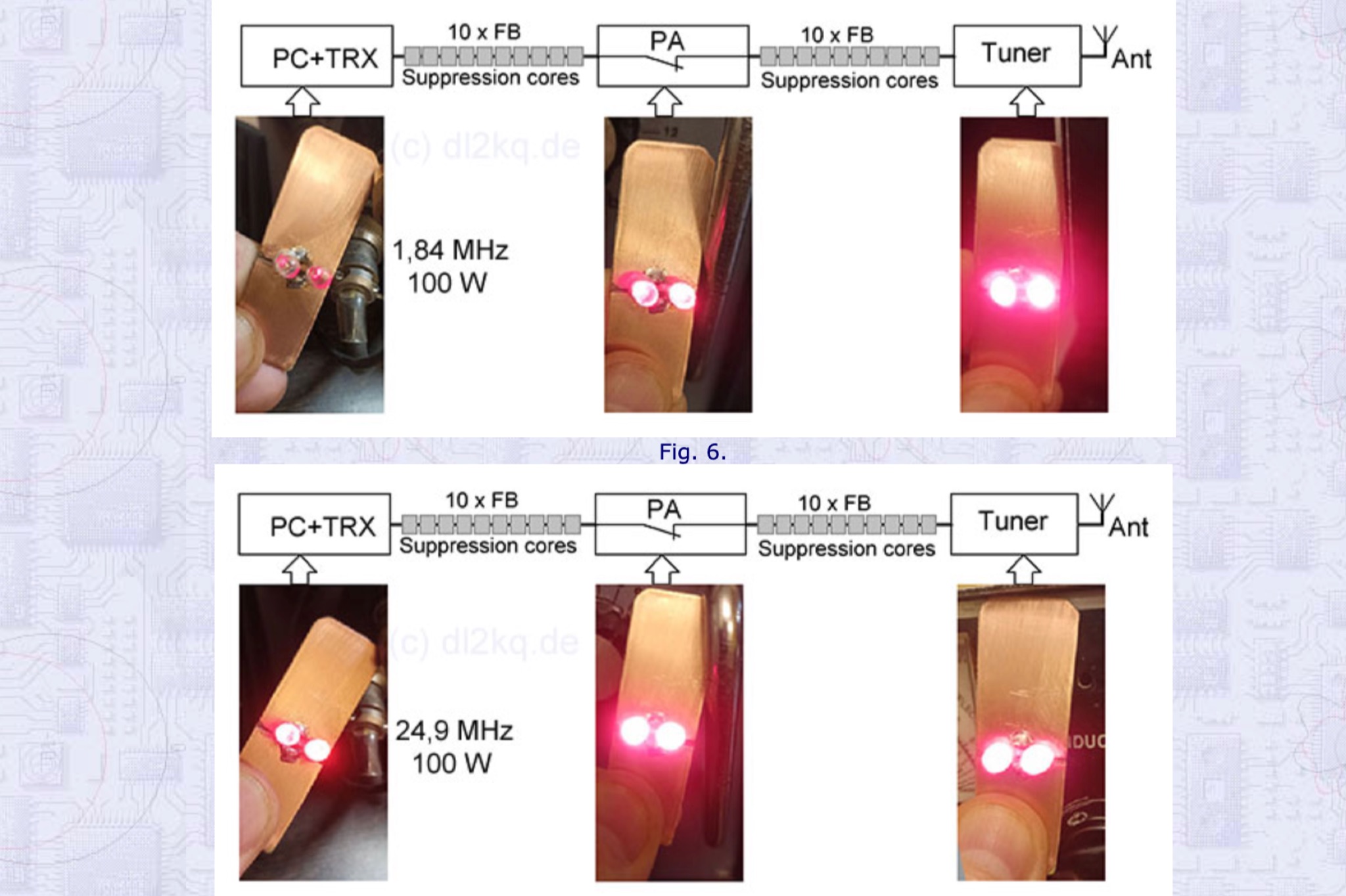 Detecting stray RF voltages on station grounds, chassis, and interconnecting cables is crucial for preventing program and hardware failures in the shack. This article details the construction and application of an LED RF V-probe, which offers significantly higher sensitivity compared to conventional neon lamp indicators. The probe leverages two specific properties of modern red LEDs: their ability to glow at microampere currents and their rectification capability at frequencies up to tens of megahertz. The design features a simple circuit with two LEDs, allowing for indication of both positive and negative RF voltage half-waves. The minimum detectable RF voltage is approximately 2 V, a substantial improvement over the 40-60 V threshold of neon bulbs. The resource illustrates the probe's physical construction on a PCB and provides a direct comparison demonstrating its superior sensitivity in detecting RF fields near a coil. Two operational modes are described: a non-contact mode for high RF voltages (above 15-20 V) and a direct-contact mode for measuring lower RF voltages, with a safety caution for the latter. Practical examples show the probe's use in analyzing RF voltage distribution across a radio station setup at 1.84 MHz and 24.9 MHz, revealing insights into common-mode current issues and the effectiveness of mitigation strategies like adding radials.
 -
 Demonstrates optimizing an **ON4UN-type 4 Square antenna** for enhanced performance across the lower HF bands, specifically 160m through 10m. The article details a design that utilizes a single support structure for the vertical elements, significantly reducing construction complexity and cost compared to traditional multi-tower setups. It emphasizes the use of **elevated radials** to achieve improved gain and a lower receive noise floor, providing insights into the design principles and practical installation tips for this directional array. K0UO shares his experience with this low-cost, high-gain solution, including the integration of a hybrid coupler phaser. The author's field testing confirms the benefits of elevated radials in achieving better far-field performance. The optimized 4 Square design offers a practical alternative for hams seeking a directional array without the extensive infrastructure typically required. Comparisons are drawn to traditional ground-mounted radial systems, highlighting the superior gain and reduced noise characteristics observed with the elevated configuration, making it a compelling option for DXing and contesting on the lower HF frequencies.
 -
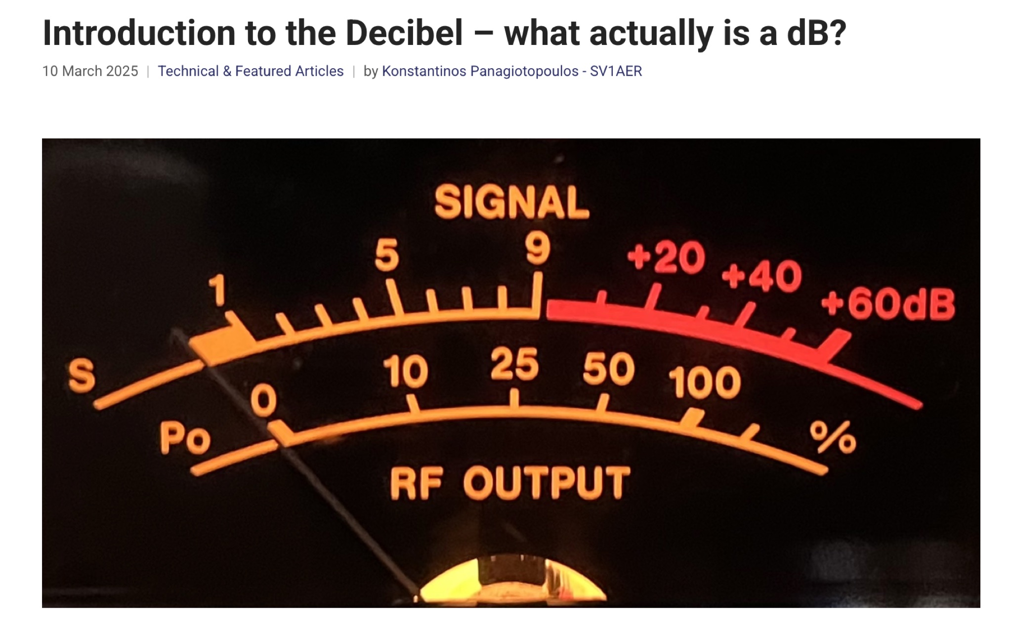 This article provides a comprehensive introduction to the decibel (dB), its logarithmic nature, and its applications in power, voltage, and antenna gain calculations. It explains how dB simplifies comparisons in electronics, telecommunications, and audio perception. The author clarifies key mathematical concepts, including power ratios, voltage doubling, and absolute levels like dBm and dBV. The discussion on S-units and antenna system gain is particularly relevant for radio amateurs. Overall, this is an informative and well-structured guide to understanding and applying decibels in technical fields.
 -
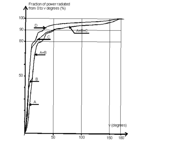 This paper by Leif Asbrink (SM 5 BSZ) presents a practical approach to designing very high gain Yagi antennas, focusing on the "brute force" optimization method. The method, described in a previous article, ensures convergence independent of initial guesses. The paper provides detailed tables of element lengths and positions for Yagi antennas optimized for 144.1 MHz with a 50-ohm feed point impedance, aiming for minimal losses and high accuracy in comparisons.
 -
 The ICOM IC-R75, introduced in 1999, operates on 13.6 Volts DC and measures 241 by 94 by 229 mm. Its coverage spans from 30 kHz to 60 MHz, making it a versatile receiver for various bands. The review details available accessories, including optional filters and the **UT-106 DSP module**, which significantly enhances signal processing capabilities. Performance comparisons are drawn against other notable receivers such as the Drake R8B and earlier ICOM models, providing context for its audio quality and overall functionality. User feedback is integrated, offering practical insights into its daily operation and reception characteristics across the spectrum. This analysis offers an in-depth look at the IC-R75's technical capabilities and features, serving as a valuable reference for operators interested in this **legacy receiver**.
 -
 Fram2, the first human spaceflight in polar orbit, launches spring 2025 aboard SpaceX's Falcon 9. Inspired by the polar exploration ship Fram, the mission highlights innovation and exploration. Four astronauts from Europe and Australia will orbit Earth for 3–5 days, including ham radio operator Rabea Rogge, who will transmit SSTV images for an educational competition. Open to students aged 16–25, the contest challenges teams to identify polar-related sites. Fram2 collaborates with ARISS to inspire STEAM learning through space communications.
 -
 This page provides a detailed comparison between the Zero Five and Gap Titan ham radio antennas. The author shares their personal experience with both antennas, highlighting pros and cons for each. They discuss aspects such as ease of assembly, customer service, tuning capabilities, performance on different bands, and the need for grounding and tuning. The comparison aims to help readers make an informed decision on choosing the best antenna for their needs, based on real-world usage scenarios and feedback.
 -
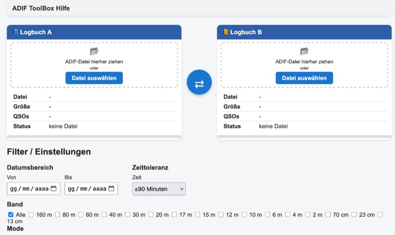 The DH1DA ADIF-ToolBox, version 1.0.0.0, released on August 29, 2026, provides a utility for managing amateur radio logs. It enables users to compare two **ADIF** files, identify differences, and filter QSOs based on criteria such as date, band, and mode. The software also supports merging ADIF files and exporting the filtered or merged results into a new ADIF file, streamlining logbook management for contesters and DXers. This web application features a graphical user interface (GUI) that simplifies logbook analysis. It is designed to handle standard ADIF data, allowing for efficient manipulation of QSO records. The tool's primary functions include a detailed comparison view, flexible filtering options, and robust export capabilities. Contact information for the developer, DH1DA, is provided, indicating direct support for the application. The tool is categorized under Software/Log Converters, emphasizing its role in ADIF data manipulation.
 -
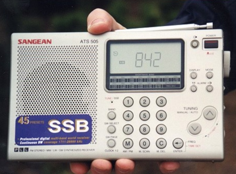 Examines the Sangean ATS-505 portable receiver, a unit introduced in March 2000, providing an in-depth analysis of its capabilities. The review details critical specifications such as its 6 Volt DC power requirement, utilizing 4 AA batteries, and its physical dimensions of 128 x 214 x 39 mm, weighing 840 g without power cells. Frequency coverage spans **LW** from 153-279 kHz, **MW** from 520-1710 kHz, **SW** from 1711-29999 kHz, and FM from 87.5-108 MHz, making it a versatile listener for various broadcast types. Key features highlighted include a backlit display for low-light operation, 45 memory presets for quick access to favorite stations, and the inclusion of Single Sideband (SSB) mode, which is crucial for serious shortwave listening and utility monitoring. The review also draws technical comparisons with other Sangean models, specifically the ATS-404 and ATS-909, pointing out differences in band coverage and operational features. This independent assessment offers practical insights into the ATS-505's performance, helping enthusiasts understand its place within the portable receiver market.
 -
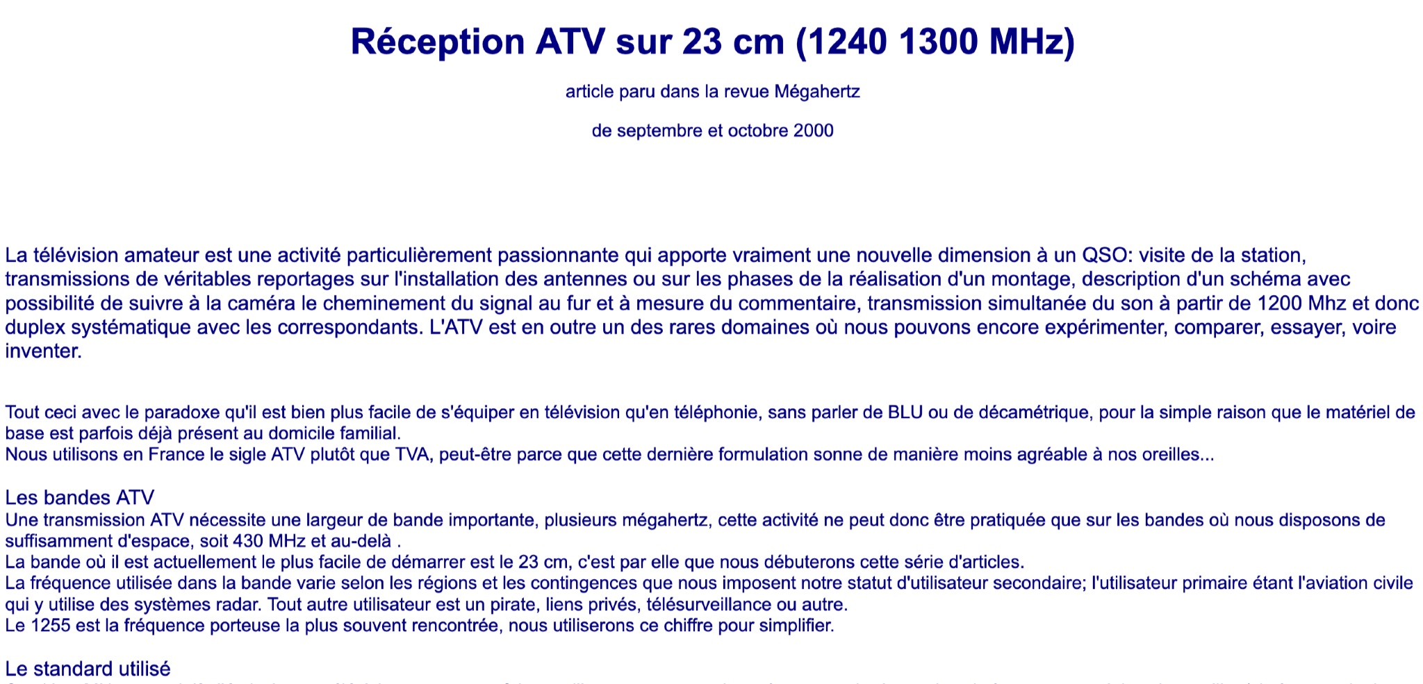 Learn about Amateur Television (ATV) on the 23 cm band (1240-1300 MHz) in this article from the September and October 2000 issue of Mégahertz magazine. Discover how ATV adds a new dimension to QSOs by allowing hams to visit stations, transmit real reports on antenna installations, follow signal paths on camera, and have simultaneous sound transmission. Explore the world of ATV experimentation, comparison, and innovation, made easier by existing equipment in many ham radio operators' homes. Find out about the ATV bands, bandwidth requirements, and the 23 cm band as a starting point for ATV activities.
 -
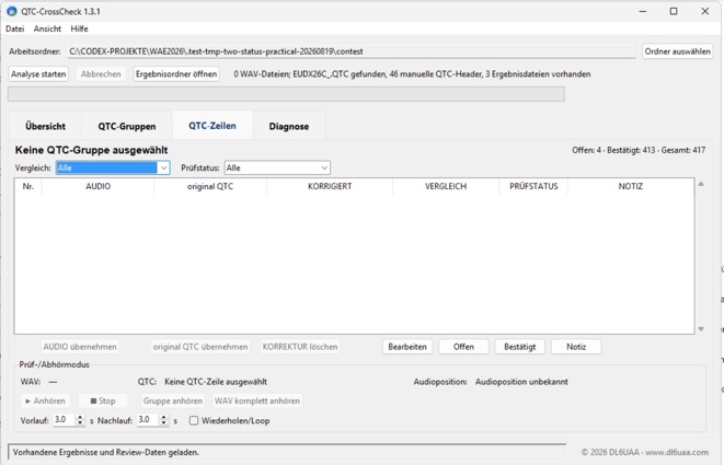 QTC-CrossCheck 1.5.0 is a free offline Windows tool for reviewing WAEDC CW QTC traffic. It analyzes QTC groups from local WAV recordings and supports comparison with UCXLog QTC data. Integrated audio playback helps verify individual QTC rows and resolve discrepancies. The portable application requires no installation or internet connection. Download the Windows ZIP archive and extract it fully before running QTC-CrossCheck.exe. A SHA-256 checksum is provided for download verification.