Search results
Query: step
Links: 212 | Categories: 0
-
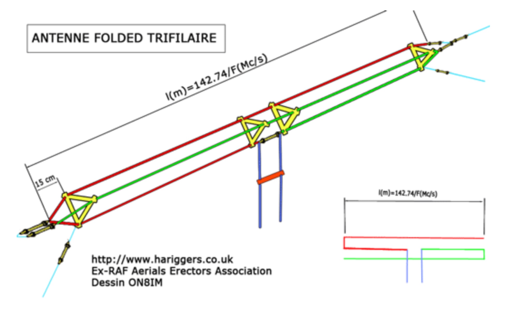 Learn how to design and analyze a folded trifilar antenna for the 80-meter band. Based on a description from RAF antennas between 1940 and 1970, this article provides step-by-step guidance on modeling the antenna, calculating resonance frequency, adjusting dimensions, and verifying performance. Perfect for hams looking to improve their antenna setup for better transmission and reception on the 80M band.
 -
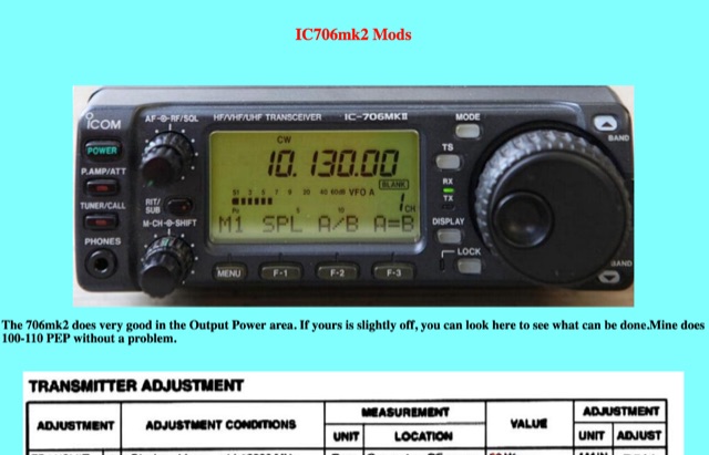 Presents two distinct hardware modifications for the Icom IC-7300 transceiver, detailing the necessary steps for each. The first modification, a _MARS_ transmit expansion, involves the physical removal of specific surface-mount diodes (D422) from the main board, enabling transmit capabilities across a broader frequency range, including out-of-band frequencies. It specifies the diode location on US versions of the IC-7300 and suggests using small diagonal cutters if a soldering iron is not preferred or available. The second modification focuses on the internal antenna tuner, aiming to provide wider impedance matching capabilities. This involves adding a **100k ohm** resistor to a designated point within the tuner circuit. The resource also briefly mentions a microphone modification for the _HM219_ and a general power increase, though without specific instructions for the latter two. It emphasizes safety precautions, such as disconnecting power and inspecting the work area.
 -
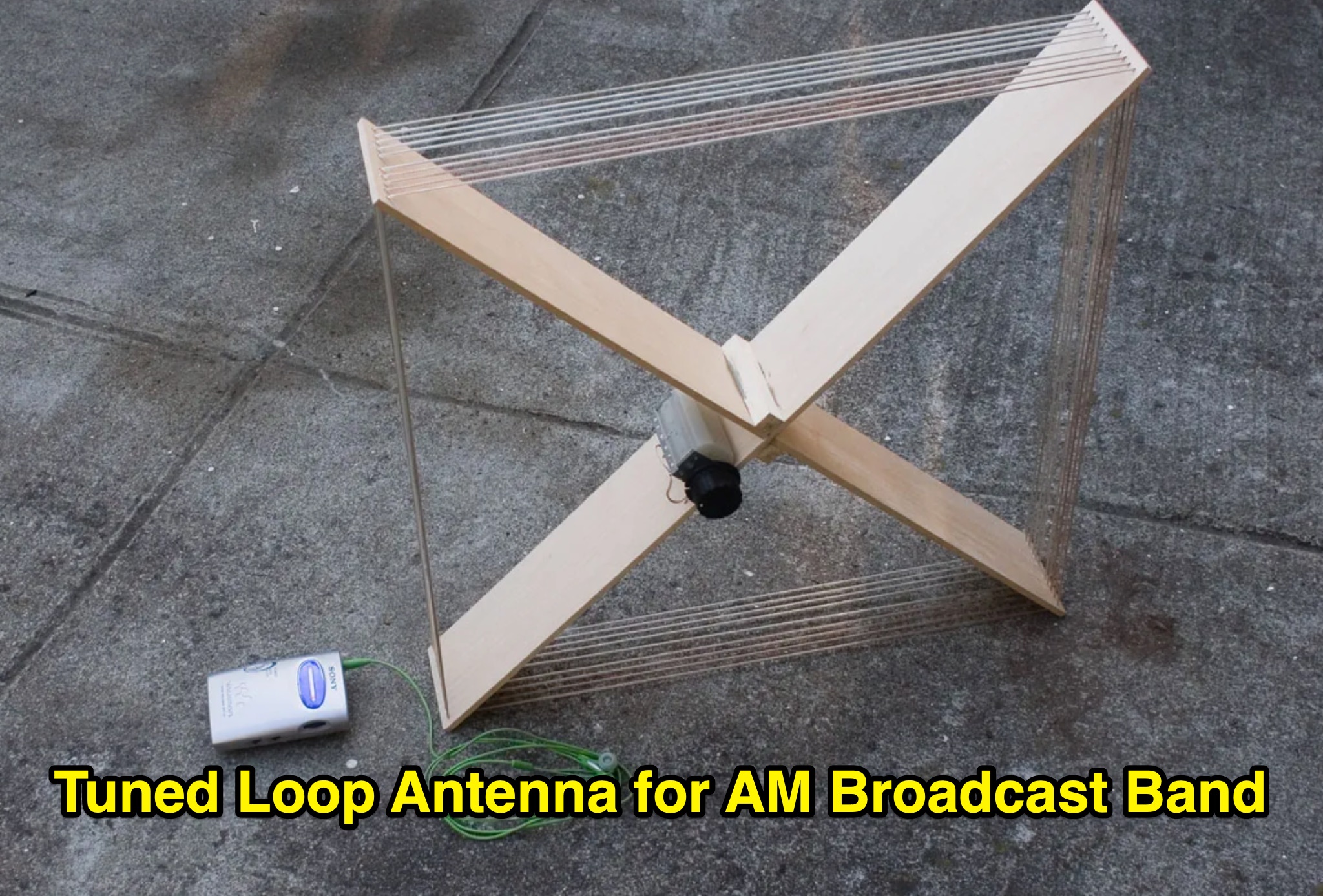 Learn how to build a simple tuned loop antenna for the AM broadcast band to improve the performance of your radio receiver. Discover how to construct a loop antenna with readily available materials, such as balsa and basswood, without the need for specialized woodworking tools. Follow step-by-step instructions to create a portable loop antenna that offers good gain and directivity, ideal for pulling in weak stations. Enhance your Ultralight DX'ing experience and explore the world of FSL antennas through this practical DIY project.
 -
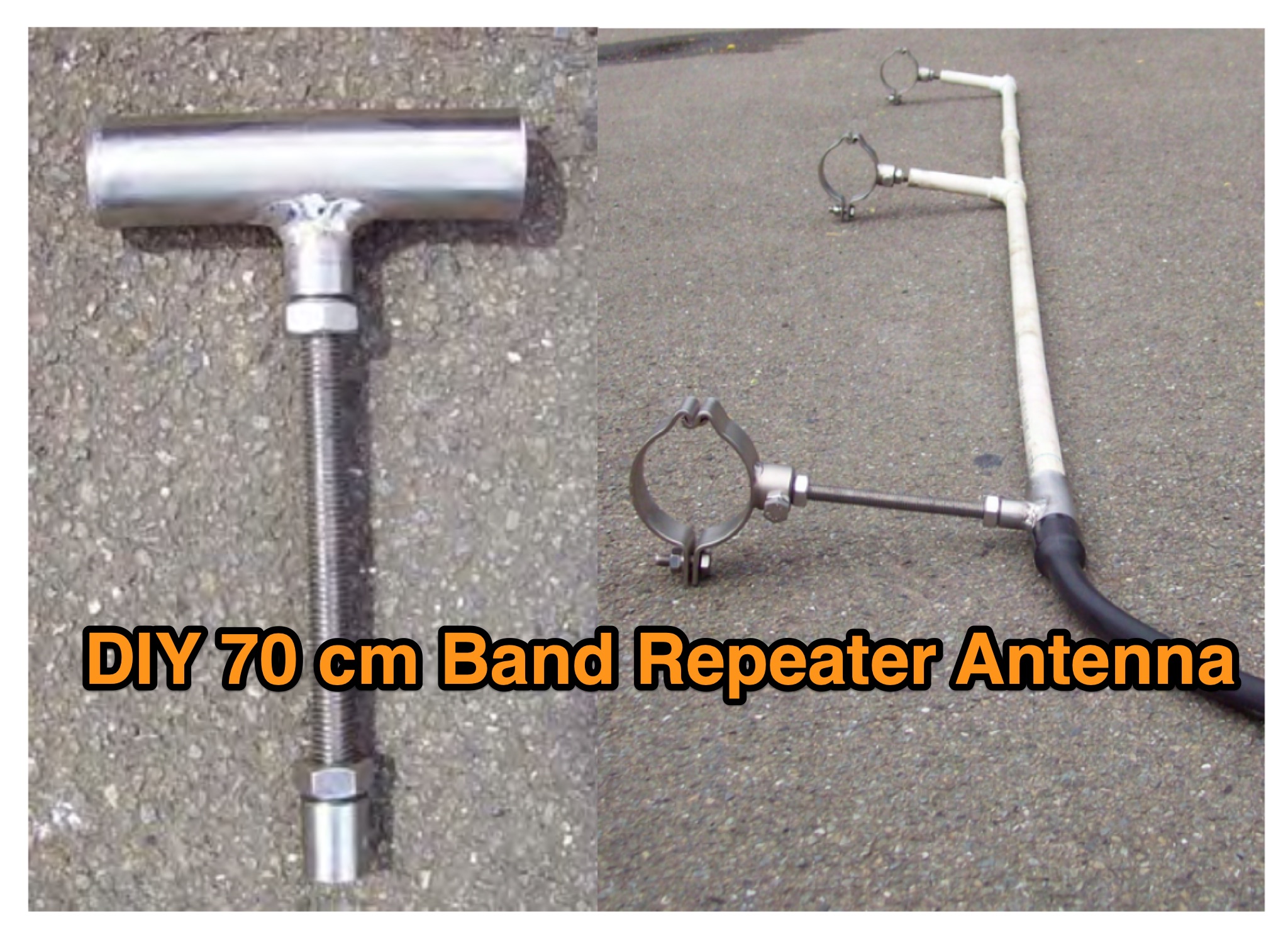 This page provides a detailed step-by-step guide on building a 70 cm band repeater antenna for hams. The instructions are clear and easy to follow, making it suitable for both beginners and experienced operators. The antenna design is optimized for the 70 cm band, ensuring efficient communication for local repeater systems. Whether you're looking to improve your repeater setup or just starting out in amateur radio, this guide will help you build a reliable and effective antenna for your station.
 -
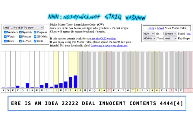 The **Nilex Morse Tutor** is an HTML5 web application designed to teach Morse code reception, adapting to user proficiency by adding new characters as readiness is detected. It prioritizes practice on less familiar letters, numbers, symbols, words, and phrases, while minimizing repetition of already mastered elements. The program offers multiple learning orders, including "Q7ZG..." (Ward/Jim's), "KMRS..." (PU5EPX/Koch), "KMUR..." (lcwo.net), "AENT..." (CWops CW Academy), "TEAN..." (Stephen C Phillips), "ANET..." (Vic VE3YT), and "ETI5..." (Ham Whisperer), alongside an alphabetical option. Users can customize the learning experience by enabling or disabling automatic progression, and selecting specific content categories such as numbers, symbols, words, phrases, QSO bits, Ham Radio Bands, X+Y=Z math, and units. Audio settings are adjustable for volume, speed (WPM), tone frequency, and keyshape/keying envelope, allowing for a personalized auditory environment. The interface provides visual feedback with blue bars indicating practice emphasis and gray bars for reserved characters, with clickable bars for manual character selection. Developed by "Nosey" Nick Waterman, VA3NNW, this tutor is based on earlier versions by Jim Wilson and a 1977 QST article. A significant October 2019 rewrite incorporated a new WebAudio sound library by AwesomeAidenW, improving offline functionality and mobile support. The content library was expanded to include 3000 top Google words, 2284+ General Service List words, ISO country codes, capital cities, US states, Canadian provinces, UK counties, common names, periodic table elements, quotes, Q-codes, electronic components, ham abbreviations, and example call signs. The software is distributed under the GNU GPL V2 license.
 -
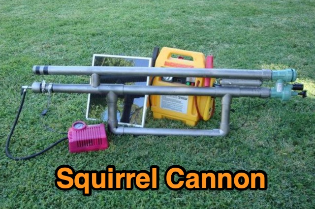 The Squirrel Cannon article humorously recounts the author's struggle with troublesome squirrels and his creative efforts to deal with them. Frustrated by failed attempts using bamboo spears and slingshots, the author ultimately constructs a spud gun—originally intended for launching antennas into trees, but humorously rebranded by his wife as a "squirrel cannon." The article provides step-by-step instructions, a parts list, and a line drawing for building this practical spud gun, making it a useful tool for antenna enthusiasts while serving as an amusing anecdote.
 -
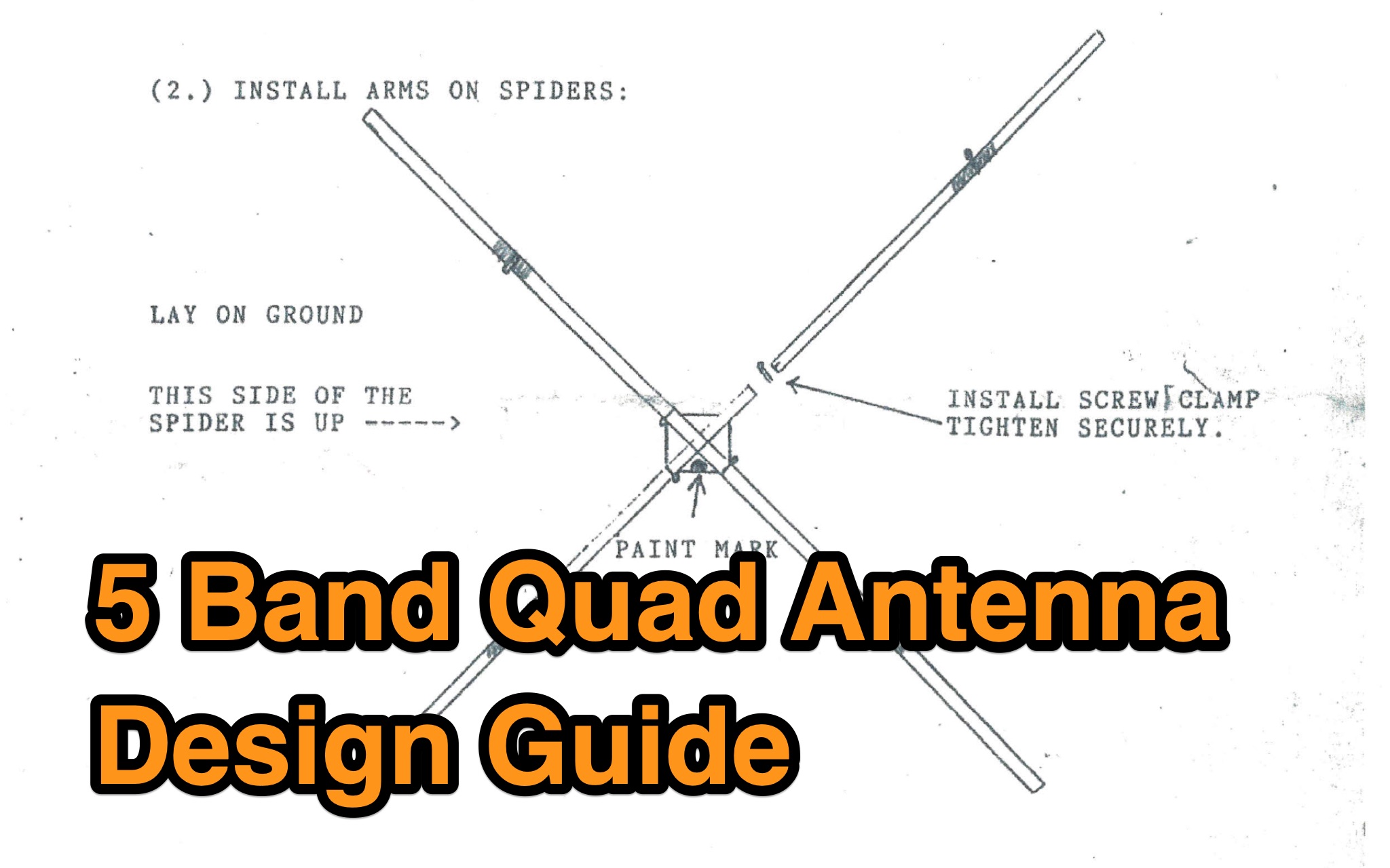 This guide provides detailed information on designing a 5 Band Quad Antenna for ham radio operators. It covers the necessary materials, dimensions, and construction steps required to build the antenna. The guide aims to help hams optimize their antenna setup for maximum performance on five different bands. Whether you are a beginner or an experienced operator, this resource can assist you in creating an effective antenna system for your station.
 -
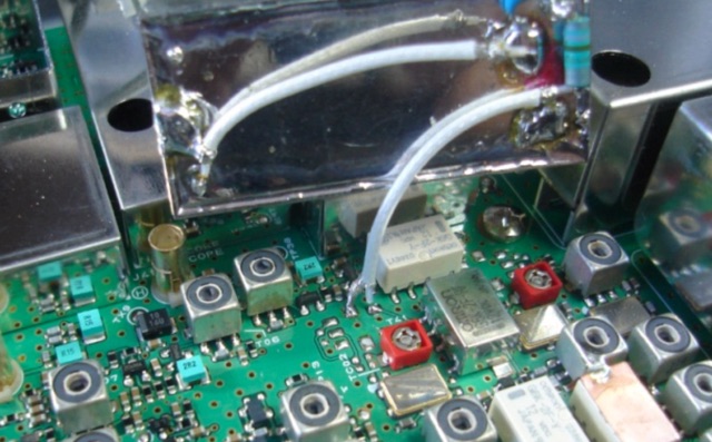 A step by step guide to install the NS Roofing filter into the Yaesu FT-2000
 -
 This project details the construction of a compact, circularly polarized Quadrifilar Helix Antenna (QHA) designed for 146 MHz operation. The antenna features a 1/2λ1/2λ helical design with a 2.6:1 aspect ratio, providing 4.5 dB gain and a spheroid radiation pattern. It is ground plane independent and compatible with both vertical and horizontal polarizations, making it ideal for terrestrial and space communications. The design includes step-by-step instructions for building the antenna using readily available materials like aluminum rods, PVC pipes, and RG-58 coaxial cable. The antenna's performance has been validated through comparisons with commercial omnidirectional antennas, showing superior results.
 -
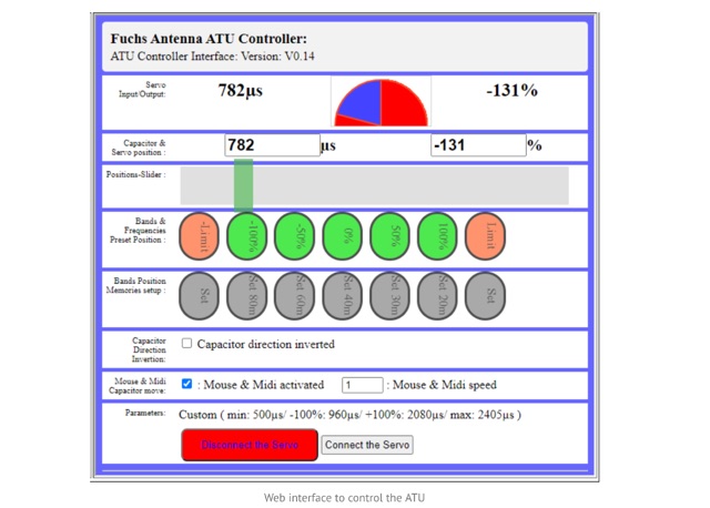 The Fuchs Antenna tuner with a resonant circuit as a coupler. The Fuch Antenna Tuner is providing a high-efficiency compare to a 49:1 transformer using ferrite . The Fuchs tuner is a resonating L/C circuit to step-up the impedance from 50 Ohm to the required 3k. The ATU is able to perform automatic tuning with the addition of a tiny Aduino Nano and a SWR bridge.
 -
 Newsletter article detailing the step-by-step construction of a 2m Hentenna using copper pipes, including user experiences and performance evaluations
 -
 This DIY guide details constructing a 5-element Yagi antenna for VHF frequencies. Yagi antennas offer directional signal transmission/reception compared to omnidirectional ones. The guide covers material selection (aluminum, screws, etc.), design using software or formulas, and step-by-step assembly including cutting elements, drilling holes, and attaching the coaxial cable. While calculations are provided for a 146 MHz design, adjustments are necessary for different frequencies. Safety precautions and potential result variations are emphasized.
 -
 This project outlines the construction of a simple TEFV (Tilted End-Fed Vertical) antenna suitable for backyard or park installations. The design requires basic materials such as 100 feet of coated stranded copper wire, wood stakes, metal ground rods, a non-conductive fiberglass pole, and essential tools like wire cutters and a soldering iron. The antenna is supported by a 20-33 feet tall pole and includes a 9:1 unun for impedance matching and a resistor for tuning. Step-by-step instructions guide the assembly, from preparing the wire and pole to connecting the unun and resistor, ensuring a functional and durable setup for outdoor use.
 -
 Notes, hints and tips on starting with morse code, how to approach learning the code, how and when to get on the air, learning and using abreviations, common Q-Codes and a sample morse code QSO.
 -
 Constructing an effective antenna support system often involves safely elevating wire antennas into trees or over obstacles. This resource details the build process for the WT8WV "Colossus" air cannon antenna launcher, a pneumatic device designed to project a pilot line over elevated structures. It specifies the use of readily available PVC pipe components and standard hardware, outlining the exact materials required and providing step-by-step assembly instructions for a robust, low-cost solution. The article presents a practical alternative to traditional methods like slingshots, emphasizing the launcher's utility for Field Day operations and general antenna deployment. It includes a comprehensive list of parts, such as 2-inch and 1-inch PVC pipe, various fittings, a sprinkler valve, and a bicycle pump valve, detailing their integration into the final assembly. The total cost for materials is estimated at around $40 per unit, making it an accessible project for many radio amateurs. Crucially, the guide incorporates essential safety precautions for operating a pneumatic launcher, covering aspects like pressure management and projectile selection. It also features multiple photographs illustrating the construction phases and the completed device, offering visual clarity to aid builders in replicating the design.
 -
 The project details the construction of a portable multiband mobile antenna, designed for rapid deployment with an _Elecraft KX3_ for /M operations. It utilizes a coil and the car body as a counterpoise, enabling operation across multiple HF bands. The article presents a table of coil tap positions for 40m, 20m, 17m, 15m, and 10m, along with corresponding SWR measurements, demonstrating an SWR below 1.5:1 on all tested bands. Photographs illustrate the antenna's components, including the coil winding and mounting mechanism, and its deployment on a vehicle. The author provides insights into the antenna's performance characteristics, noting its resemblance to a vertical dipole despite the unconventional ground plane. The resource includes a parts list and construction steps, making it reproducible for other radio amateurs.
 -
 Constructing a double bazooka antenna for the UHF band, specifically tuned for 435 MHz, involves a straightforward process detailed with step-by-step imagery. The design leverages readily available _RG213 coaxial cable_, cut to precise lengths derived from formulas: 140.208 / F (MHz) for the radiating element and 99.06 / F (MHz) for the coaxial section. This approach yields a highly effective vertical polarization antenna, suitable for local ragchewing or repeater access. My own field experience with similar coaxial designs confirms their robustness and ease of deployment. The article emphasizes critical steps like short-circuiting cable extremities, interrupting the braid at the center, and securing an insulating support. It also covers preparing the definitive mounting with a quality feedline, noting that RG58 is acceptable for temporary use but better options exist for permanent installations. Weatherproofing is crucial for longevity, achieved through PVC electrician's tube, glue, and heat-shrink tubing. The final assembly is designed for mounting on a small aluminum mast, with the feedline routed internally. The reported SWR measurement is very satisfactory, showing approximately **+/- 3%** HF return, indicating excellent impedance matching at the target frequency.
 -
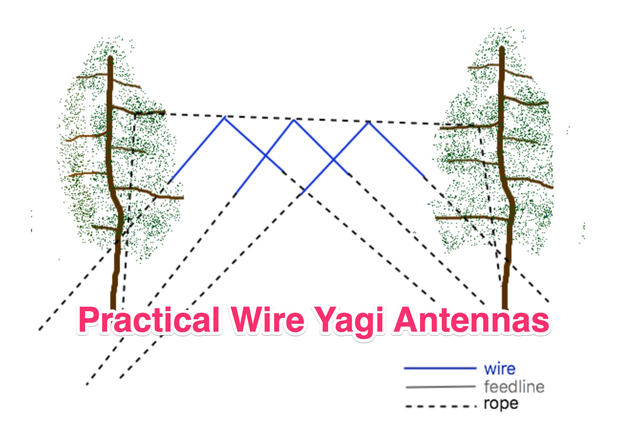 Learn how to build wire Yagi antennas for your ham radio setup. Discover how smaller wire elements can offer practical and portable options for temporary operations. Explore designs like the Hex Beam, Spider Beam, and Moxon that require less mechanical complexity and can be easily rotated or supported. Find out how to construct and hang wire Yagis from ropes, trees, or masts with inverted vees or horizontal elements. Get tips on element positioning, gain, and beamwidth considerations. Follow simple construction steps using a rope boom and marking element positions for efficient assembly. Enhance your ham radio experience with versatile wire Yagi antennas.
 -
 A homebrew spectrum analyzer, the Specan, provides a crucial measurement capability often missing from the typical amateur radio shack, allowing for detailed analysis of RF signals up to 70 MHz. This double-conversion superheterodyne receiver design incorporates 112 MHz and 12 MHz intermediate frequencies, utilizing an _Si570_ as the local oscillator for fine tuning down to 1 Hz steps. It offers two resolution bandwidths: 300 KHz for broad spectrum sweeps and 1 KHz for precise close-in distortion measurements, achieving an 80 dB spur-free dynamic range at 1 KHz resolution. The project, a reboot of the classic _W7ZOI/K7TAU_ design from November 1998 QST, integrates an _Arduino_ microcontroller for controlling the Si570, managing a front-panel LCD, and communicating with a PC for spectrum plotting. This approach significantly reduces cost compared to commercial units, making advanced RF diagnostics accessible to homebrewers. The Specan can measure carrier suppression, VFO cleanliness, antenna VSWR, transmitter harmonics, and filter passband shapes, providing insights beyond what an oscilloscope or frequency counter can offer. Construction emphasizes modularity and careful shielding, with each stage built and tested individually on unetched copper clad board. The design includes detailed instructions for integrating the Arduino, building the Si570 oscillator, and aligning the various modules, often using the Specan itself for calibration. It requires a well-regulated linear power supply and can be built with common tools and readily available components, making it a practical and rewarding endeavor for those looking to enhance their RF test bench.
 -
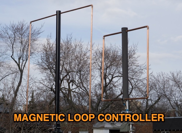 Unveil the secrets of efficient Magnetic Loop Antenna control systems, eliminating the hassle of frequent retuning. With real-time tracking and compatibility with various transceivers, including popular models from Elecraft, ICOM, Kenwood, and Yaesu, this controller ensures seamless frequency adjustment. Explore its high-resolution stepper motor and versatile communication capabilities, revolutionizing amateur radio operation.
 -
 Getting started with LoRA a documented experience with LoRA Gateway, Antennas and simple application
 -
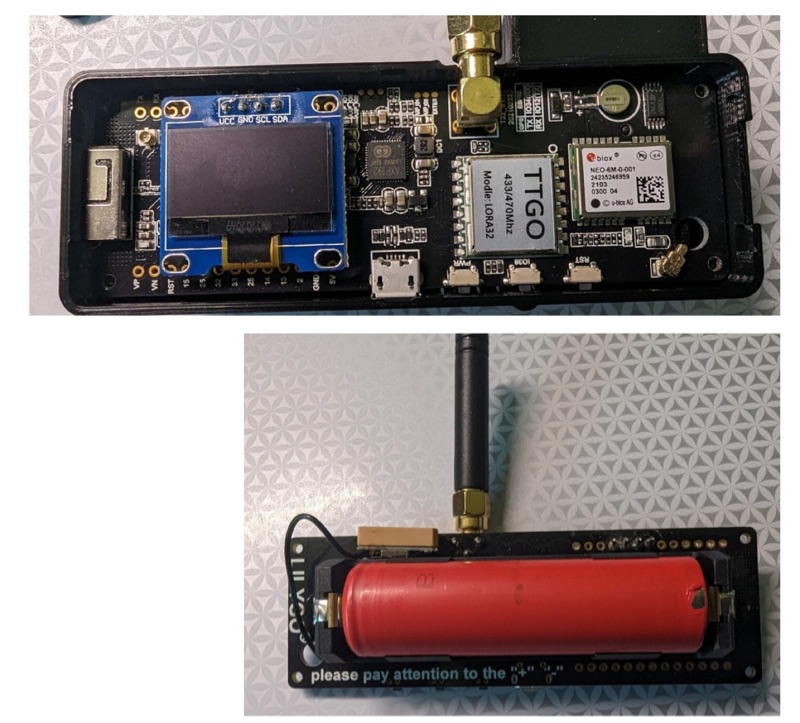 The resource details the construction of a 433 MHz LoRa APRS iGate and a tracker, both built around _TTGO T-Beam v1.1_ microcontroller boards. Each board integrates an OLED screen, WiFi, GPS, and an SMA antenna connector, powered by an 18650 3.7 V lithium-ion battery or microUSB. The iGate operates on 433.775 MHz, with its status verifiable on aprs.fi, demonstrating practical implementation of LoRa-based APRS solutions. The methodology involves programming the modules using Visual Studio Code with the PlatformIO plugin. This process loads the necessary firmware and a JSON configuration file, which includes the operator's callsign and WiFi credentials for the iGate. The guide emphasizes the ease of programming and provides specific steps for configuration. Initial testing of the iGate and tracker, including smart beaconing configuration, is documented. The low power output of approximately 200 mW from the LoRa board's transmitter is noted, with suggestions for range extension through improved antennas or RF amplification. The author, N4MI, plans to deploy a higher-gain 70cm antenna for the iGate.
 -
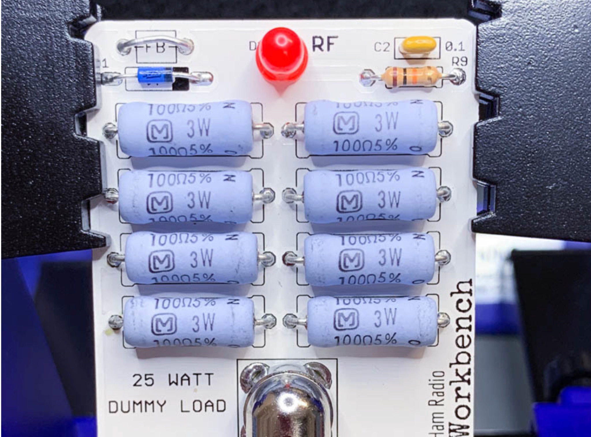 This page provides a detailed guide on building a 25 Watt QRP dummy load for hams. It includes a list of required parts and supplies, along with a documentation section. The project is aimed at hams interested in QRP operations and looking to build their own dummy load. The page offers step-by-step instructions and resources to help hams successfully complete the project.
 -
 The resource details the construction of a J-pole vertical antenna specifically engineered for motorcycle mounting, addressing the common issue of interference with top cases. It outlines the fabrication process, beginning with an aluminum angle bracket for secure attachment to the lateral support, followed by the creation of the antenna's base from an 8mm threaded rod bent into a U-shape, approximately **40mm** wide. The article specifies the precise method for coaxial cable connections using eyelets and 3mm screws, ensuring robust contact. Further construction steps involve fitting a 10mm aluminum tube onto the threaded rod, with a screw securing the radiating element and establishing core contact. The design prioritizes mechanical stability against vehicle vibrations over fine-tuning SWR with sliding collars. Initial testing yielded a _SWR_ of **1.2** across a significant portion of the band, with improvements noted by optimizing the coaxial braid contact point near the support bracket. The document provides practical insights into material selection and assembly, emphasizing durability for mobile operation. It concludes with aesthetic options, allowing the builder to paint the antenna or retain its natural aluminum finish, making it a functional and adaptable solution for UHF motorcycle communications.
 -
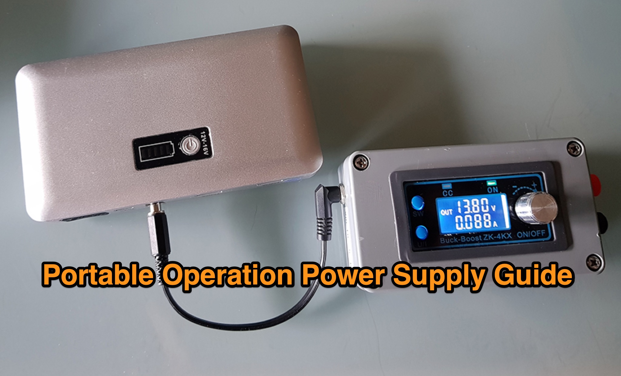 The _Icom IC-705_ portable operation power supply guide details the use of a car battery jump starter and a step-up/down converter for field power. It examines various power supply types, including LiFePO4 batteries, lead-acid batteries, and supercapacitors, discussing their respective advantages and disadvantages for QRP and portable setups. The resource emphasizes practical considerations such as capacity, weight, discharge rates, and charging methods crucial for reliable off-grid operation. The article compares the energy density and cycle life of different battery chemistries, noting that LiFePO4 batteries offer significantly more cycles (e.g., **2000-5000 cycles**) compared to lead-acid batteries (e.g., **300-500 cycles**). It also touches upon the integration of solar panels for recharging and the importance of proper voltage regulation to protect sensitive radio equipment, providing insights into maximizing operational time during DXpeditions or POTA activations.
 -
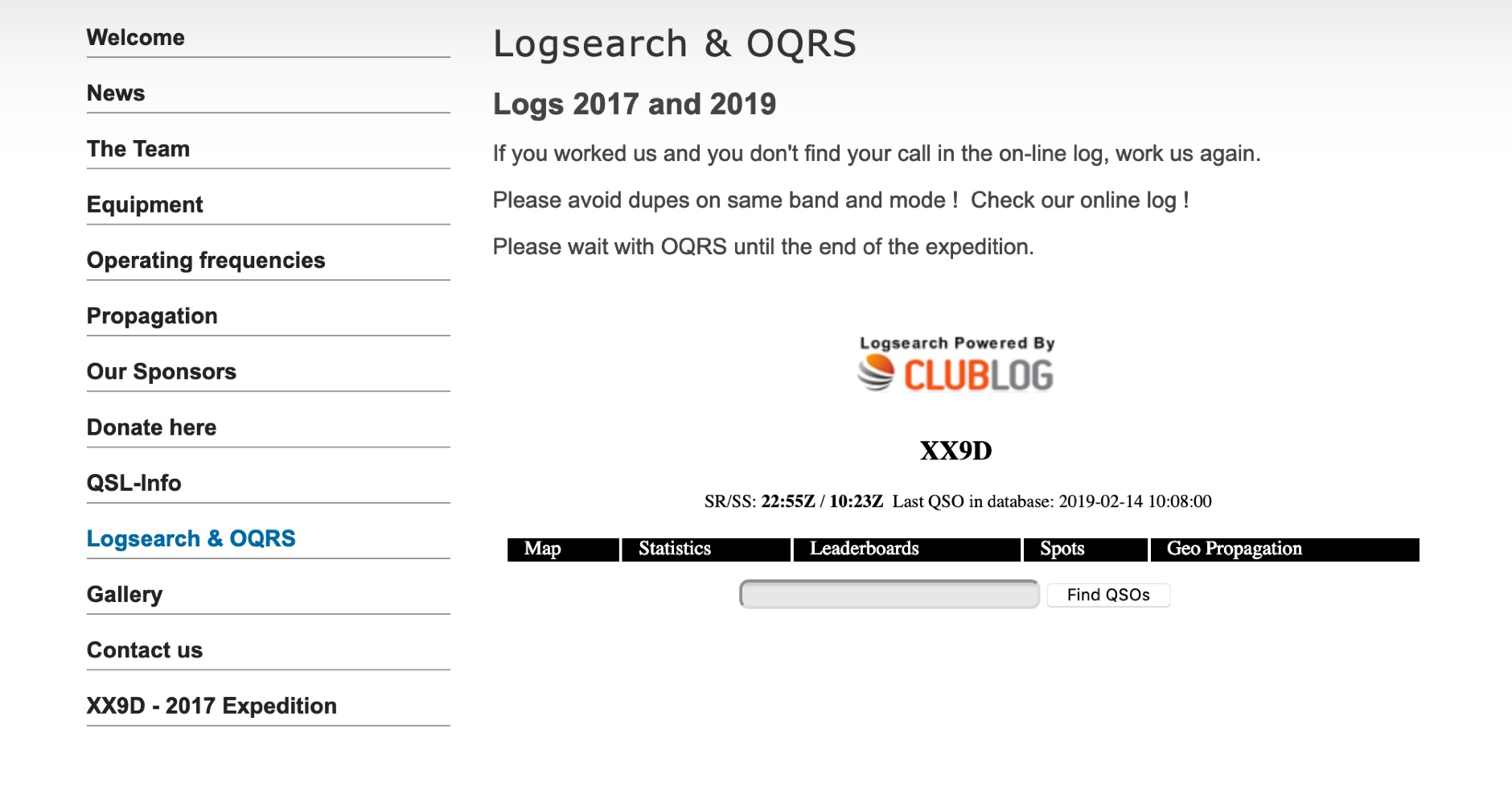 The XX9D Log Online provides a direct log search function for the DXpedition to Macao, specifically detailing operations conducted in 2017 and 2019. This service allows amateur radio operators to verify their contacts (QSOs) with XX9D, a critical step for QSL card management and award applications. Users are explicitly advised to consult the online log to prevent duplicate contacts on the same band and mode, optimizing efficiency during active DXpedition periods. This online tool supports the "DX Code Of Conduct," promoting ethical operating practices within the amateur radio community. The platform facilitates the Online QSL Request System (OQRS), streamlining the process for requesting QSL cards without the need for traditional bureau or direct mail methods. Operators are instructed to defer OQRS submissions until the conclusion of the DXpedition, ensuring all logs are finalized. The log search interface is powered by CMSimple, a content management system, indicating a straightforward, database-free web application. The resource is designed for ease of access, providing a clear method for DXers to confirm their contacts and manage QSL requests efficiently.
 -
 This document provides comprehensive guidance on modeling and constructing multiband dipole antennas using traps. It addresses common segmentation issues in EZNEC modeling software, recommends optimal segment lengths for trap models, and compares trapped dipoles with paralleled multiband dipoles. While trap dipoles are significantly shorter, they exhibit lower gain and narrower bandwidth. Detailed instructions for building weatherproof coaxial traps include material lists, construction steps, and tuning methods. The guide notes that properly constructed coaxial traps introduce only minimal signal loss (0.6 dB) while offering practical multiband performance in a compact design.
 -
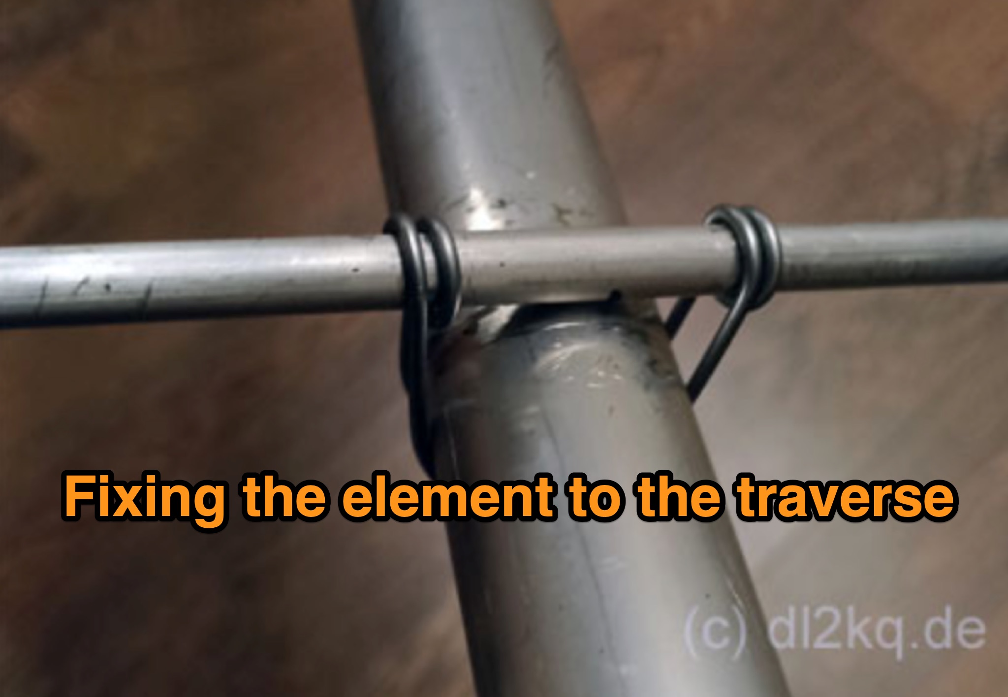 This article provides a cost-effective and reliable method for fixing antenna elements in the traverse of HF/UHF Uda-Yaga antennas. It outlines a step-by-step process using soft galvanized steel wire, eliminating the need for special adapters or additional holes. The method described ensures a secure attachment without compromising the mechanical strength of the traverse, offering a durable solution for ham radio operators constructing antennas. The use of galvanized steel wire guarantees long-lasting stability, making it a practical and efficient technique for antenna assembly.
 -
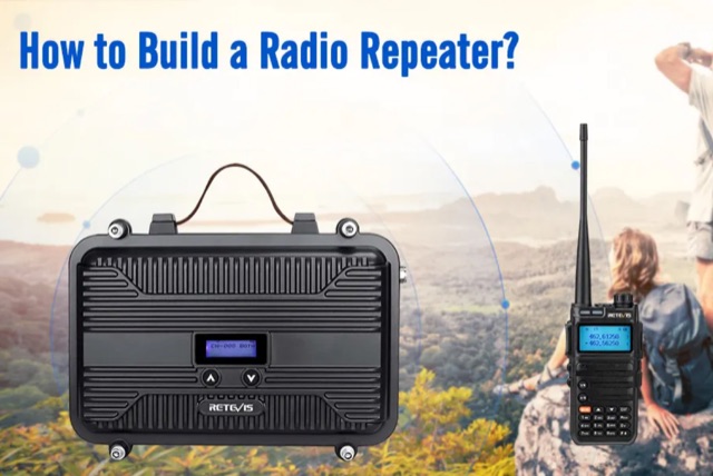 Building a radio repeater enhances communication by extending signal range and overcoming obstacles like mountains or buildings. This guide explains the fundamentals of radio repeaters, their function, and a step-by-step DIY approach. Key steps include conducting a site survey, selecting an optimal installation location, and configuring the system with suitable equipment such as the Retevis RT97 series. Proper placement, antenna setup, and testing ensure effective operation, making this process accessible for enthusiasts aiming to improve communication reliability and range
 -
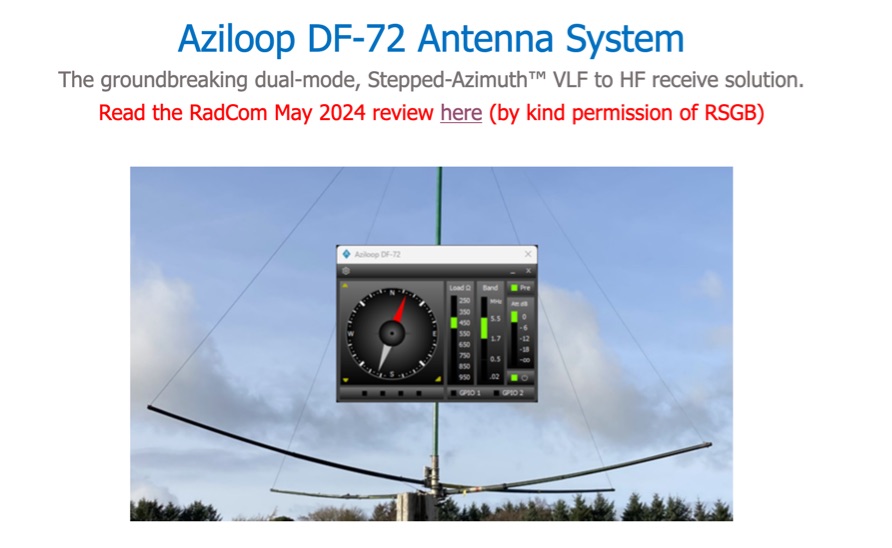 The Aziloop DF-72 antenna system provides 72 K9AY headings and 36 loop axes, allowing for rapid switching in 60 ms. It integrates a switchable 18 dB preamp, a 4-step attenuator (0-18 dB), and four 7-pole preselection filters to optimize receiver performance. The K9AY load is adjustable from 250 Ohm to 950 Ohm in 50 Ohm increments, offering flexibility for various receiving conditions. Control is managed via an intuitive Windows UI, supporting Local, Client, or Server modes, with headless remote operation possible through the built-in Ethernet Server. _Omni-Rig_ support facilitates auto-filter selection, PTT muting, and Rig-Sync functionality, enhancing integration with existing station setups. Designed by _GW4GTE_, the system utilizes a low visual impact, small-footprint antenna with orthogonal loops and an earth connection. It is suitable for general monitoring, co-channel station resolution, basic direction finding, and interference reduction across the VLF to HF spectrum.
 -
 The recognition of telegraphy masked by noise at 40 and 80 signs/min telegraphy speed was studied in 10 normal-hearing subjects at different sound pressure levels (25-85 dB SPL in steps of 5 dB) as well as at different test frequencies (2000, 1000, 800, 630, 500 and 250 Hz). The ability to recognize the signs varied with varying SPL. Recognition for most of the subjects was best at an SPL close to 70 dB. All subjects improved their recognition as the frequency was lowered to 500 Hz, some even at 250 Hz. These facts should be taken into consideration when training telegraphy operators as well as in the construction of radio receivers to permit listening at low frequencies. Furthermore, the critical ratio was calculated at the different test frequencies.
 -
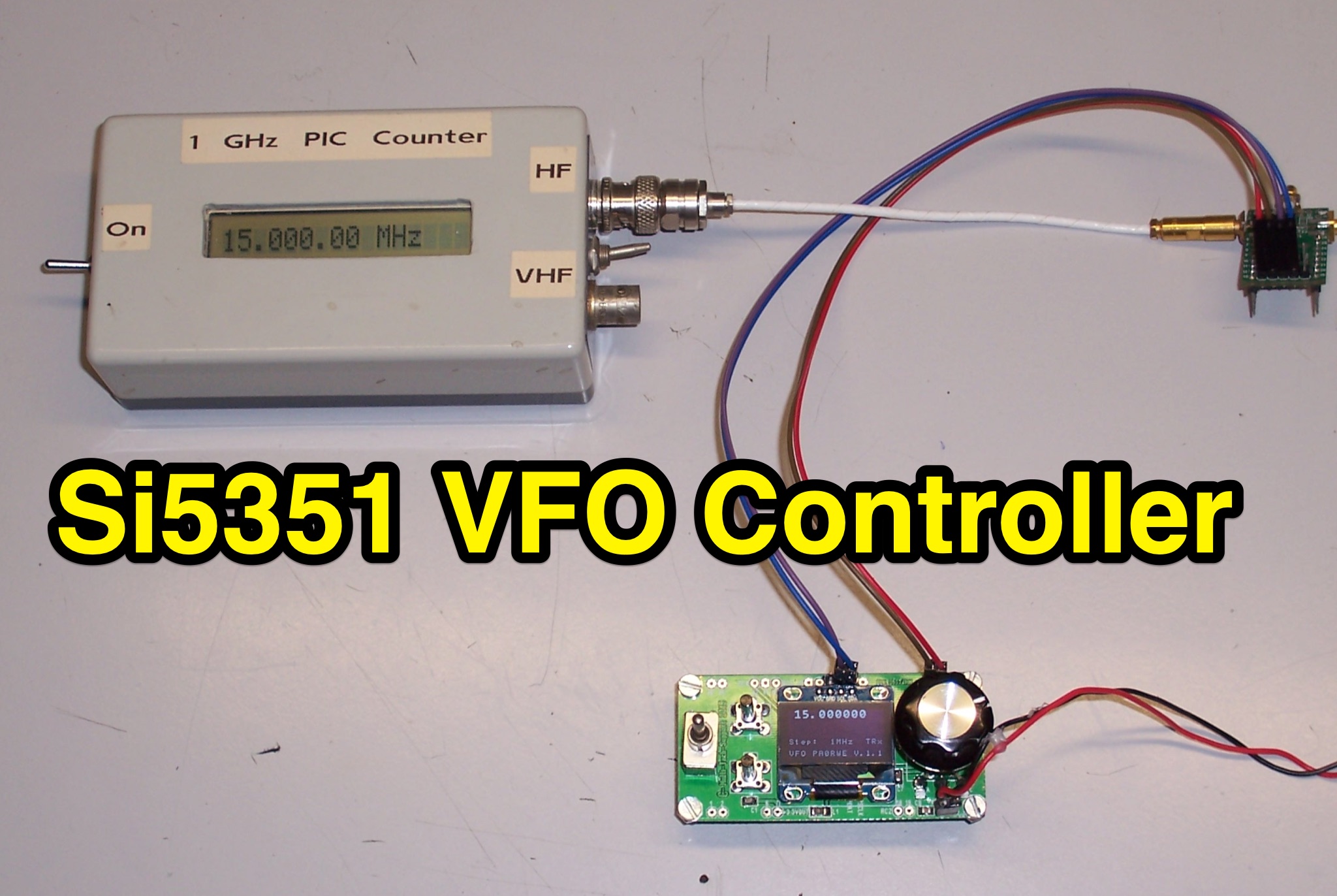 Learn how to build a VFO controller based on the Si5351 for ham radio operators. This controller consists of a PIC16F1825 and OLED SSD1306 display, with clock outputs for Tx, Rx, and IF frequencies. Features include calibration, RIT function, and the ability to tune frequencies separately. With step-by-step instructions and schematics, you can easily create your own VFO controller for your amateur radio setup.
 -
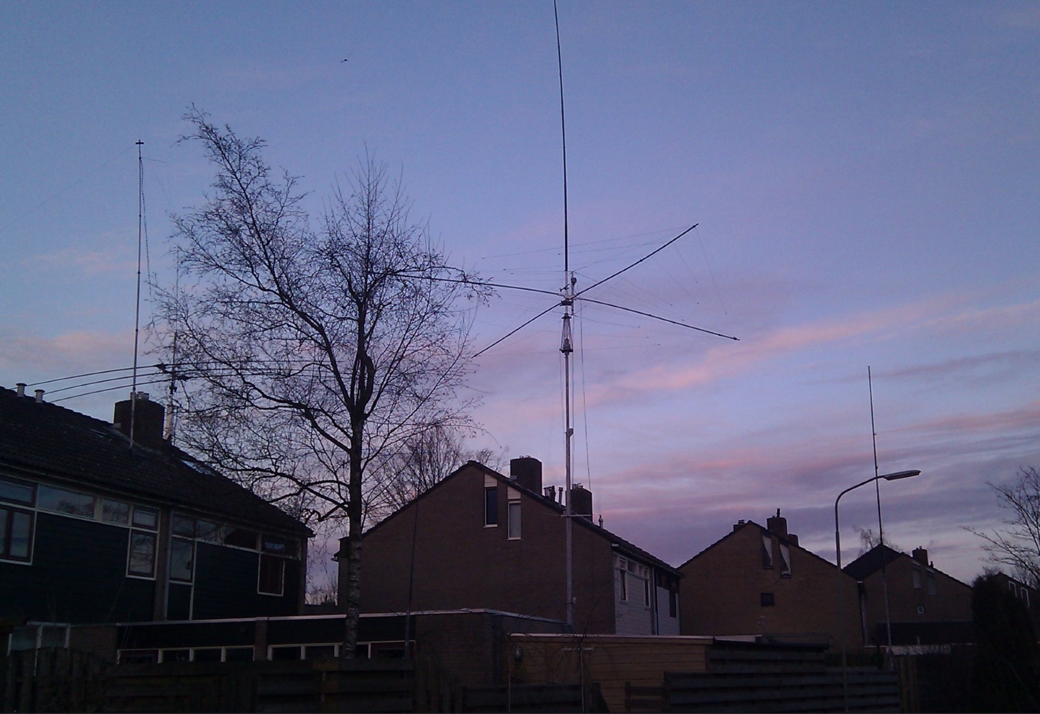 A custom center hub for a Spiderbeam yagi antenna, enabling side-mounting on an existing mast. Challenges included structural instability, limited reach for assembly, and interference with a pre-mounted Spiderpole. A new hub using 40x40mm aluminum tubing provided strength, allowed side assembly, and supported fiberglass pole guy lines. The solution facilitated efficient installation and removal, delivering excellent performance compared to a SteppIR yagi.
 -
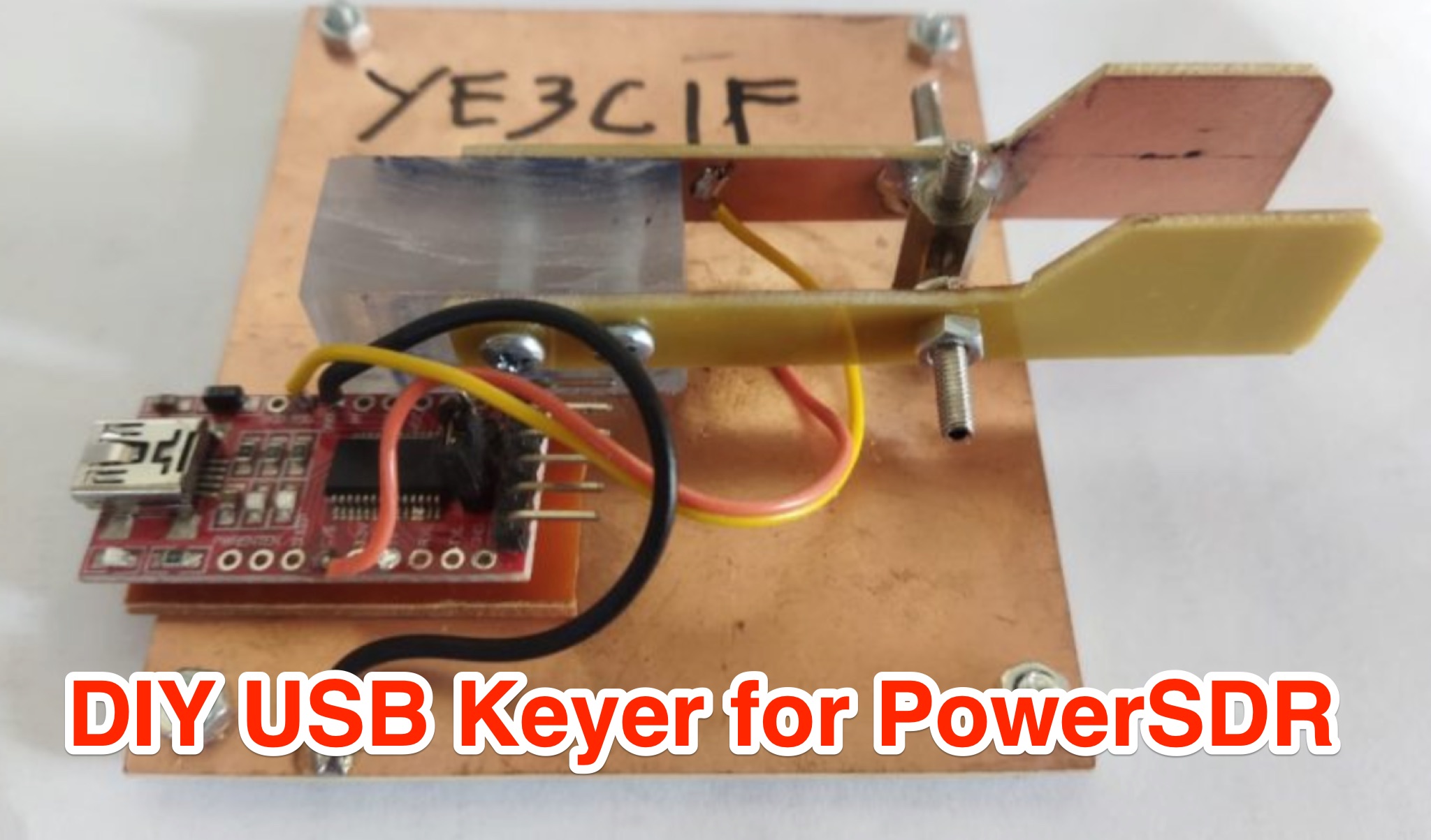 Learn how to create a USB Keyer for PowerSDR to enhance your CW experience. This article provides a step-by-step guide using affordable materials like a USB to TTL Module (FT232RTL) and a Keyer iambic. The tutorial includes a detailed wiring diagram and instructions for configuring the Keyer in the PowerSDR menu. The author also shares a helpful video demonstration to ensure smooth operation. Whether you're a seasoned ham operator or new to CW, this DIY project can improve your radio setup. Follow these instructions to build your USB Keyer and elevate your PowerSDR experience.
 -
 The _DX EXPLORER_ blog serves as a personal chronicle of amateur radio experiences, particularly emphasizing homebrew projects and DIY radio equipment. It provides insights into constructing various transceivers and receivers, such as the Minimalist CW Transmitter and the Sputnik Regenerative Receiver, offering practical guidance for those new to the hobby. The content often details the assembly and operation of low-cost kits like the $3 Pixie Transceiver, demonstrating accessible entry points into radio construction. Beyond building, the site also features reviews of commercial gear, including the Tidradio TD-H8 Radio, providing an operator's perspective on performance and utility. The author, YO6DXE, shares a learning journey, aiming to inspire fellow enthusiasts to engage with the technical aspects of amateur radio. This resource covers a range of topics from basic circuit explanations to practical operating tips, fostering a deeper understanding of radio principles. The blog's focus on personal experimentation and project documentation makes it a relevant resource for hams interested in hands-on learning.
 -
 The FT101ZD DDS VFO project replaces the original VFO in the Yaesu FT101Z/ZD rigs with an AD9850 DDS module, providing enhanced frequency control. It uses the original optical encoder and clarifier for compatibility, with a custom 6V power supply modification. The project includes selectable step sizes, a frequency save function, and works with both RX and TX modes. The design involves mechanical and electronic modifications, including SMD components and a custom PIC processor. Calibration ensures accurate frequency output, with further improvements under consideration.
 -
 Improve the FRG-7 operation adding a home made digital frequency display. The author explains the challenges of using the analogue dial on the FRG-7 and how a digital display can be a useful solution. The page provides detailed information about the FRG-7's design and frequency conversion process. It also includes step-by-step instructions on how to connect an external frequency counter to display the kHz part of the frequency.
 -
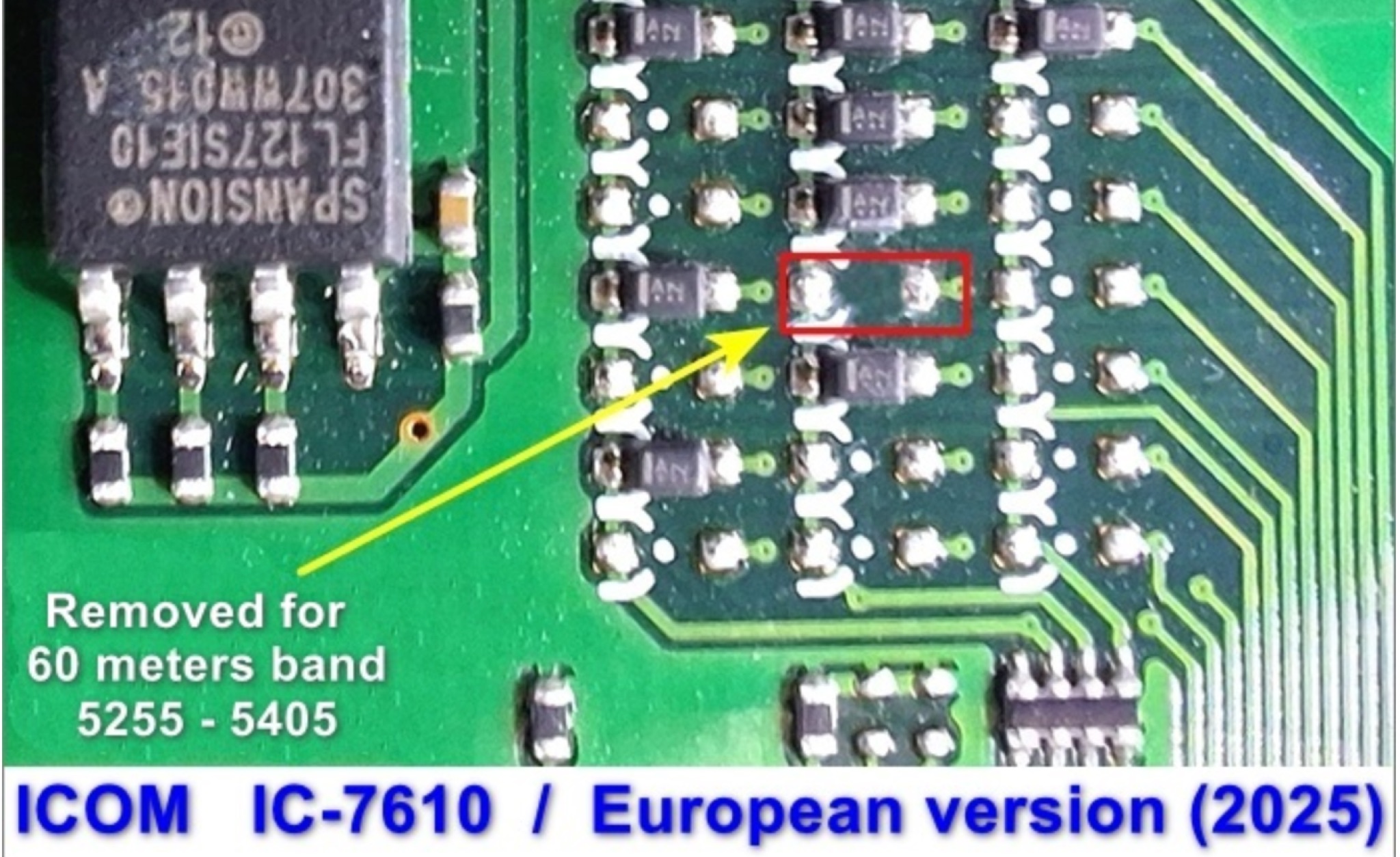 This page provides instructions for unlocking additional frequency bands on your IC-7610 transceiver to access the 60m band. The step-by-step guide is useful for hams looking to expand their operating capabilities and communicate on this popular band. By following these instructions, you can ensure that your transceiver is set up correctly to operate within the regulations of the 60m band.
 -
 This page details the construction project of the 'Stone', a QRP double conversion superhet SSB transceiver for the 40m band. The project is based on a kit from Tim Walford, G3PCJ, and includes step-by-step instructions for building and testing each stage. The author has added enhancements such as a three digit frequency counter and an automatic gain control. The content is aimed at hams interested in DIY transceiver construction and includes technical details of the build process.
 -
 This article explores the powerful features of AutoEZ as an Excel application working with EZNEC antenna modeling software. The article demonstrates how variables, equations, and formulas enable versatile antenna design and automatic optimization. Through practical examples including dipoles, inverted vees, delta loops, and monopoles, the author shows techniques for achieving resonance, implementing transmission line resonators for broadbanding, and optimizing antennas across frequency ranges. The step-by-step demonstrations cover unit conversion, coordinate calculations, segmentation considerations, and SWR optimization. This practical guide illustrates how AutoEZ extends EZNEC's capabilities, making complex antenna modeling more efficient and accessible.
 -
 Outlines the essential steps for successfully activating a **Summits on the Air (SOTA)** peak, providing a structured approach for amateur radio operators participating in this popular award program. It details crucial pre-activation planning, including navigating the SOTA website, setting up a SOTA Data account, and consulting the **Association Reference Manual (ARM)** for specific regional rules and peak information. The guide also covers using mapping resources like adventureradio.de and lists ofjohn.com to identify suitable summits and check access conditions. The document emphasizes safety during the activation, advising operators to monitor weather, carry rain gear, and plan ample time for the ascent and descent. It specifies the **4-QSO minimum** requirement within the Activation Zone and recommends calling "CQ SOTA" on traditional QRP or VHF calling frequencies. The guide also suggests using local 2m FM repeaters for safety communications and spotting, while clarifying that repeater QSOs do not count for SOTA points. Post-activation activities include submitting logs to sotadata.org.uk, uploading trip reports to share experiences with future activators, and promoting SOTA participation on various reflectors. The guide highlights the program's appeal through its awards system for both activators and chasers, encouraging new participants in North America.
 -
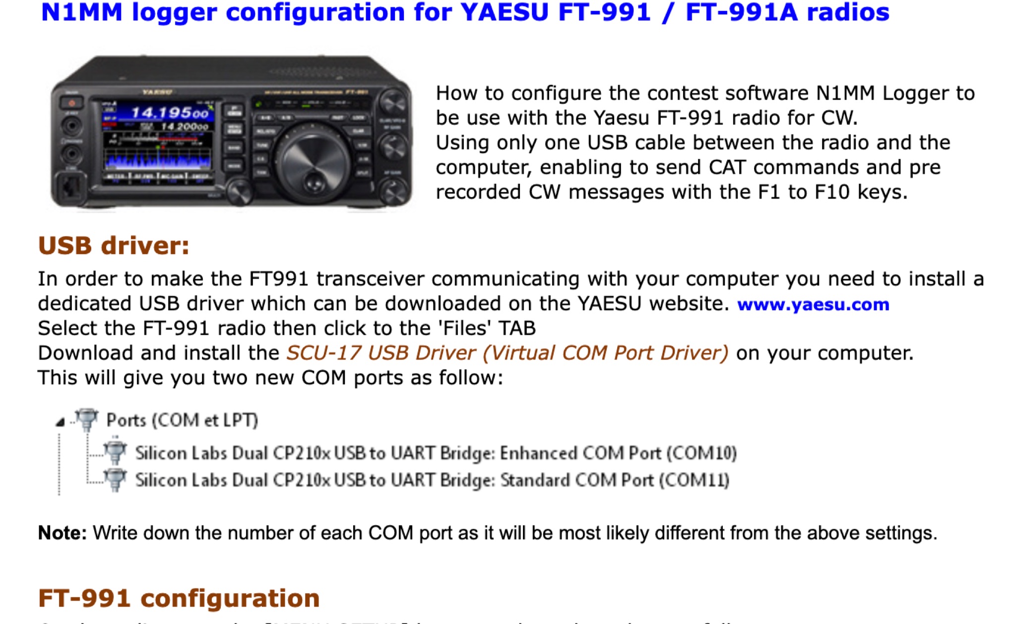 Learn how to set up N1MM Logger+ software for your FT-991 transceiver. This article provides a step-by-step guide on configuring your transceiver settings to work seamlessly with the N1MM Logger+ program. By following these instructions, hams can enhance their contesting and logging experience with improved efficiency and accuracy. Whether you are a beginner or an experienced operator, this tutorial will help you optimize your FT-991 setup for contesting and general ham radio operations.
 -
 A versatile digital VFO design utilizing the Silicon Labs Si5351a oscillator chip and Nokia 5110/3310 graphics LCD display, operating from 1-160MHz with dual VFO capability. This microcontroller-based system, powered by an ATmega328 processor, features rotary encoder tuning, selectable step sizes, RIT control, and comprehensive band memory functions. Drawing less than 40mA at 3.3V, it significantly improves upon previous DDS designs' power consumption while offering advanced features like S-meter display, VFO lock, and programmable BFO/CIO offsets. The design achieves flexible functionality through simple hardware implementation and efficient software architecture, making it particularly suitable for QRP and portable amateur radio applications.
 -
 Twenty 1-watt carbon film resistors are configured in parallel to construct a 50-ohm **dummy load** for amateur radio applications. The design incorporates a heatsink for thermal dissipation and an **SO-239 connector** for RF input, making it suitable for QRP operations. This budget-friendly project details component selection, soldering techniques, and mounting procedures, achieving a continuous power rating of 10 watts and intermittent handling of up to 100 watts across HF and VHF frequency ranges. The resource provides a step-by-step guide for assembly. This construction offers an economical solution for essential shack tasks such as antenna tuning, transmitter testing, and SWR meter calibration without radiating an RF signal. The utilization of readily available components significantly reduces the overall build cost compared to commercial alternatives, providing radio amateurs with a functional and reliable test accessory. While specific VSWR measurements are not provided, the design prioritizes practical utility for low-power transceiver diagnostics and general RF experimentation.
 -
 Learn how to connect your AllStar Node to 44Net in this blog post. Discover step-by-step instructions and tips to make the process easier for hams interested in expanding their networks. Find out how to improve your communication capabilities and enhance your overall ham radio experience with this helpful guide.
 -
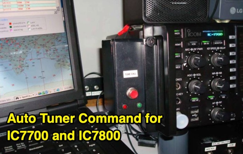 An Arduino-based interface provides a remote tuner call command for Icom **IC7700** and **IC7800** transceivers, addressing the lack of a built-in function for external tuners such as the MFJ 998RT. This setup initiates a low-power transmit signal, typically 15 watts, allowing the remote autotuner to perform its matching sequence. The article details the required CI-V line communication and modifications to existing Arduino code, specifically referencing contributions from Jean-Jacques ON7EQ for improved Icom interrogation routines. The system involves a sequence of steps: storing the transceiver's current mode and power, disabling the internal autotuner, activating a control relay to interrupt the amplifier line, switching to RTTY mode at low power, and initiating transmit. The transmit duration is manually controlled by the operator, observing the SWR meter until a low SWR is achieved, then a second button press stops the transmission. A built-in 4-second transmit limit provides a safety measure. After tuning, the routine restores the original mode and power settings, re-enables the internal autotuner, and performs a brief 2-second RTTY transmission for internal tuner adjustment. The circuit diagram includes a Panasonic form 2 relay for amp control and emphasizes critical delays in the Arduino code for stable operation at 9600 baud CI-V communication. Compatibility with logging software like DXLab, N1MM, and N3FJP is noted, with specific interrogation time settings required to avoid conflicts.
 -
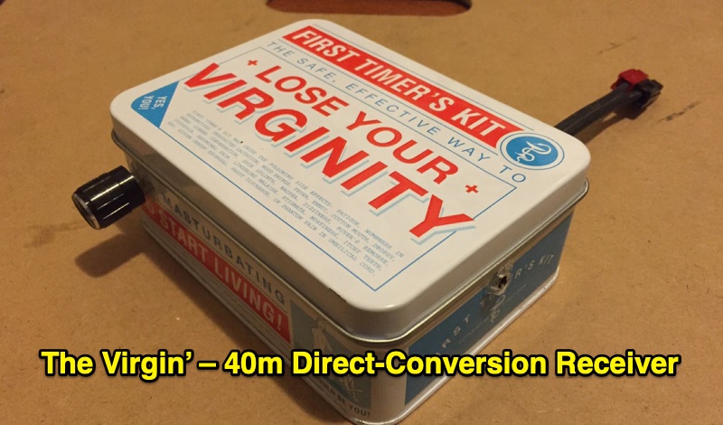 Demonstrates the construction of 'The Virgin', a **direct-conversion receiver** specifically designed for the 40m amateur radio band. This project, completed in February 2016, features a fixed operating frequency determined by a crystal oscillator, requiring a physical crystal change to alter the reception frequency. The design incorporates two integrated circuits and a power regulator, emphasizing simplicity with a single control knob. The author details the initial design, subsequent modifications to the front end, and troubleshooting steps addressing common issues like audio motorboating and power supply instability. The resource presents the final design of the receiver, reflecting the author's first experience building such a unit between December 2015 and February 2016. It offers practical insights into basic circuit construction and the iterative process of refining a homebrew radio project. The content is particularly relevant for those interested in fundamental receiver principles and hands-on **QRP** transceiver building.
 -
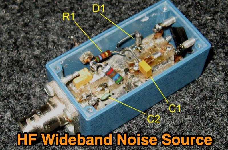 Details the construction of a **wideband noise source** for HF filter alignment, specifically targeting transceivers such as the Elecraft K2. The design modifies a Down East Microwave (DEMI) MMIC amplifier board, part number MMICPCB, by integrating a 1N4735A zener diode, 560-ohm resistors, and 4.7 nF, 10 nF, and 22 µF capacitors. This modification enables the board, originally configured for a MAR-6 MMIC (with MAR-1 as an alternative), to generate noise suitable for procedures like the K2's "CAL FIL" function. The resource provides a **schematic** and a comprehensive bill of materials, including specific component values for replication. It outlines the practical steps involved, such as removing the input connector and integrating the new components into the existing MMIC amplifier board layout. The output is optimized for wideband HF applications, ensuring compatibility with various filter alignment tasks. This project focuses on practical implementation, demonstrating how to repurpose readily available components for a critical test instrument. It offers a cost-effective alternative to commercial noise sources, leveraging existing amateur radio hardware for enhanced station maintenance and performance.
 -
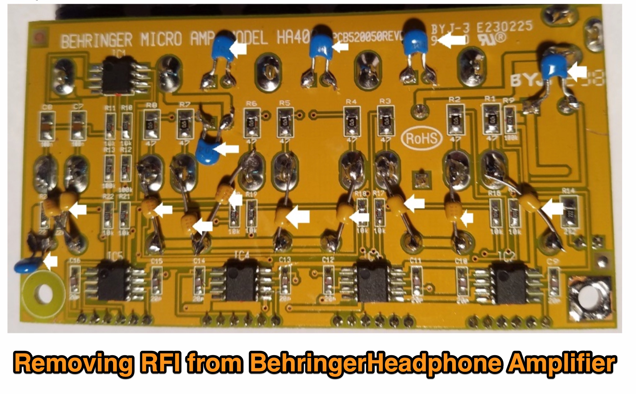 Learn how to eliminate RF interference from your Behringer HA400 headphone amplifier for a better listening experience. Discover the simple modifications needed to prevent distortion caused by RF in your audio setup. Follow the step-by-step instructions provided by WB5NHL Ham Radio to improve the performance of your headphone amplifier in ham radio activities.
 -
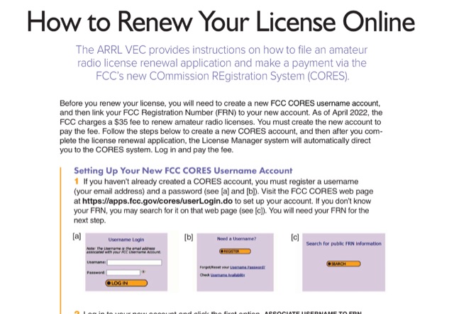 This document provides a comprehensive guide on renewing an US amateur radio license through the Federal Communications Commission (FCC) using the new COmmission REgistration System (CORES). Published on QST October 23, it outlines the necessary steps for creating a CORES account, associating it with a Federal Registration Number (FRN), and completing the renewal application. Key points include the requirement of a $35 fee for the renewal process, which must be paid online after the application is submitted. The guide emphasizes the importance of logging into the FCC License Manager system during the renewal window and provides instructions on how to navigate the renewal process, including obtaining confirmation and access to the renewed license. Additionally, it offers contact information for FCC support and links to further resources for assistance.