Search results
Query: transmit id
Links: 256 | Categories: 5
-
 Station QRP presents various **circuit diagrams** for constructing low-power AM vacuum tube shortwave transmitters, catering to enthusiasts interested in vintage radio technology. The resource details schematics ranging from simple to more complex designs, enabling hams to build their own QRP AM transmitters for operation on frequencies like 6.925 kHz AM. It emphasizes the use of vacuum tubes, providing a technical foundation for understanding and replicating classic shortwave broadcasting methods. The content is geared towards those who enjoy the hands-on aspect of electronics and the unique characteristics of tube-based RF circuits. Building these transmitters allows operators to experience the nostalgia of early shortwave radio, with the site specifically mentioning a pioneer station on 6.925 kHz AM. The designs facilitate experimentation with low-power AM transmission, offering practical application for homebrew projects. The focus on QRP (low power) operation aligns with a segment of the amateur radio community that values efficiency and minimalist setups, providing a distinct alternative to modern solid-state transceivers.
 -
 Low-frequency (LF) radio time signals, operating primarily in the 40–80 kHz range, are broadcast by national physics laboratories for precise clock synchronization. Transmitters like **JJY** (40 kHz, 50 kW; 60 kHz, 50 kW), RTZ (50 kHz, 10 kW ERP), MSF (60 kHz, 15 kW ERP), WWVB (60 kHz, 50 kW ERP), RBU (66.66 kHz, 10 kW), and DCF77 (77.5 kHz, 50 kW) cover vast geographic areas, often several hundred to thousands of kilometers. LF signals offer distinct propagation advantages over higher-band transmissions such as GPS. Their long wavelengths (3–6 km) enable effective diffraction around obstacles like mountains and buildings. The ionosphere and ground act as a waveguide, eliminating the need for line-of-sight and allowing a single powerful station to cover extensive regions. Ground wave propagation minimizes ionospheric variability effects on transmission delay, and signals penetrate most building walls effectively. Robust and low-cost receivers, often priced at 20–30 USD/EUR, are widely used in radio clocks. These receivers typically comprise a tuned ferrite core antenna, a receiver IC (e.g., Atmel T4227, U4223B, MAS1016) for amplification and AM detection, and a microcontroller for decoding the time signal and phase-locking a local clock. Specific components for DCF77, MSF, and WWVB are readily available from vendors like HKW Elektronik and Ultralink.
 -
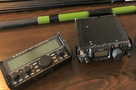 Selecting a portable QRP transceiver for field operations or SOTA activations often involves weighing trade-offs between size, power output, and feature sets. This article directly compares the _Elecraft KX2_ and the _Yaesu FT-818_, two popular choices among QRP operators. It examines key specifications such as receiver sensitivity, transmit power levels, and battery life, providing practical insights into their on-air performance. The comparison delves into user interface differences, discussing the ergonomics of controls, display readability, and menu navigation for each rig. It also touches upon integrated features like internal antenna tuners and digital mode capabilities, which are crucial for efficient portable operation. The author shares personal experiences with both transceivers, highlighting their respective strengths and weaknesses in real-world scenarios. Specific attention is given to the form factor and weight, critical considerations for backpackers and those operating from remote locations. The article concludes with a summary of which transceiver might be better suited for different operating preferences.
 -
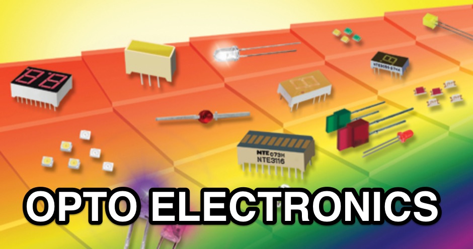 The branch of electronics dealing with devices that generate, transform, transmit, or sense optical, infrared, or ultraviolet radiation
 -
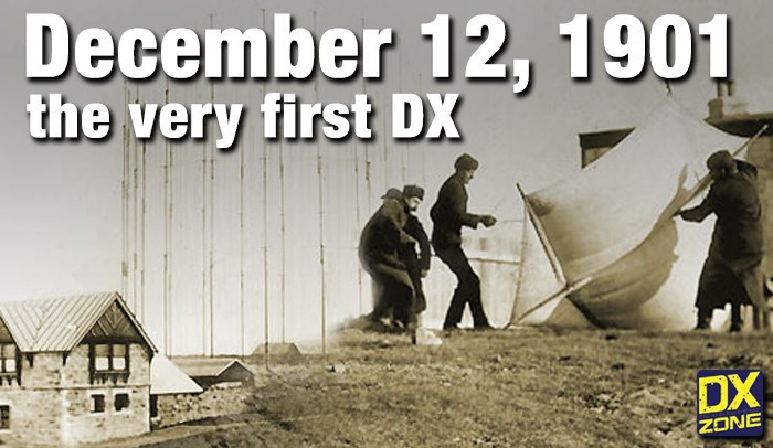 On December 12, 1901, Guglielmo Marconi successfully received the first transatlantic wireless communication, a Morse code "S" (three dots), at 04:30 GMT. This article details the setup for this groundbreaking experiment, noting Marconi's receiver in St. John’s, Newfoundland, Canada, utilized a _coherer_ and an antenna elevated by balloons and kites. The transmitting station at Poldhu, Cornwall, England, featured twenty-four 200-foot ships' masts and a 25-kilowatt alternator. The resource explains how this contact disproved contemporary beliefs about radio wave limitations due to Earth's curvature, later understood through _ionospheric propagation_. It frames Marconi's achievement as the "very first DX" in amateur radio terms, defining DX as telegraphic shorthand for distance and _DXing_ as the hobby of receiving distant signals. The article also provides external links for further reading on Marconi's experiments and the science behind transatlantic radio signal reception.
 -
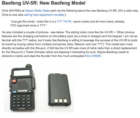 The Baofeng UV-5R handheld transceiver, introduced around 2012, operates across the 2-meter (144-148 MHz) and 70-centimeter (420-450 MHz) amateur bands, offering dual-band receive and transmit capabilities. This review provides an early assessment of the radio's form factor, user interface, and general performance, noting its compact size and the inclusion of a **VFO/Memory mode** button for frequency management. The device supports both FM and narrow FM modes, with a reported power output of 4 watts on VHF and 3 watts on UHF, making it suitable for local simplex and repeater operations. Key features discussed include its 128-channel memory capacity, a built-in VOX function, and a **DTMF keypad** for tone dialing and repeater access. The review highlights the radio's ability to scan frequencies and memories, along with a dual-watch function allowing simultaneous monitoring of two frequencies. Battery life is addressed, with the standard 1800 mAh Li-ion pack providing several hours of operation depending on transmit usage. Initial impressions cover the radio's construction and the clarity of its LCD display, which shows both A and B band frequencies.
 -
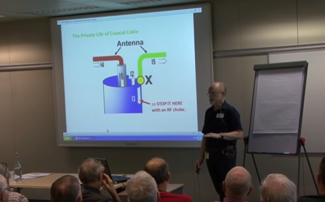 Our ideas about HF baluns have changed dramatically in recent years. The focus today is very much on suppressing unwanted common-mode RF currents, to reduce both the received noise levels and the risks of causing interference on transmit.
 -
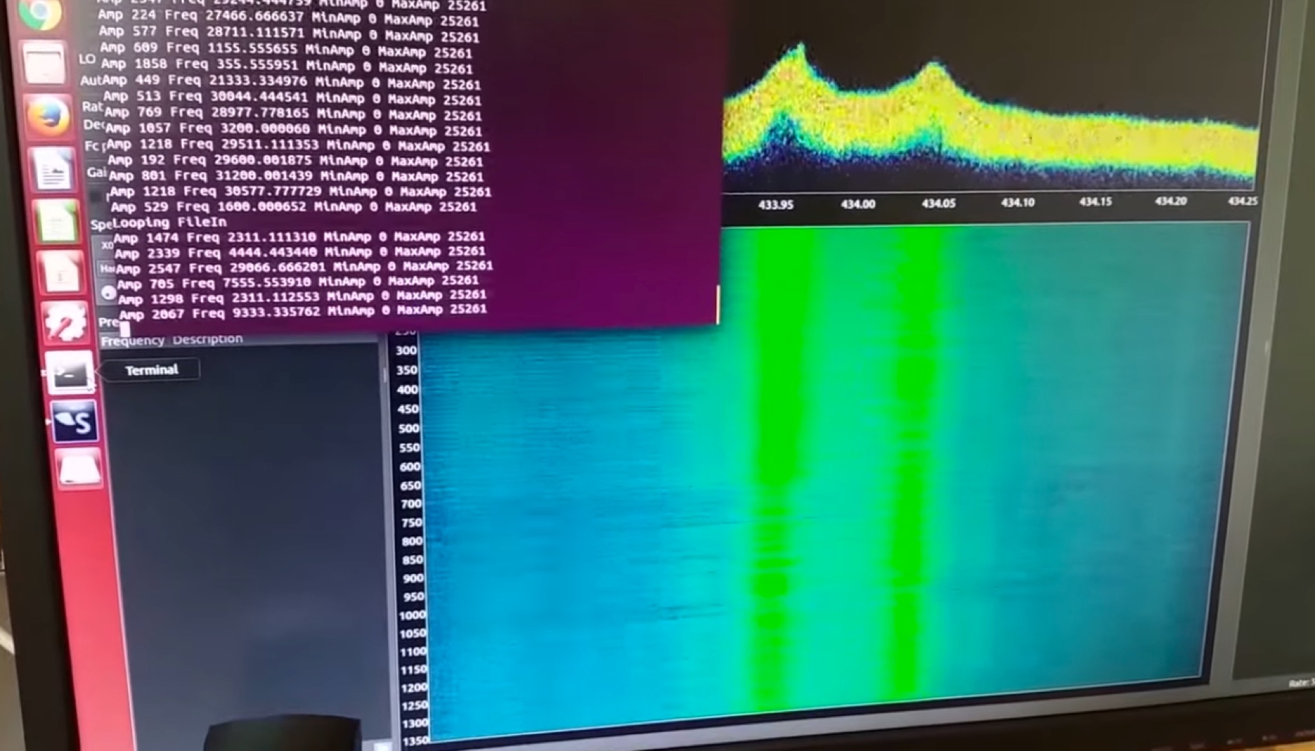 rpitx is a general radio frequency transmitter for Raspberry Pi which doesn't require any other hardware unless filter to avoid intererence. It can handle frequencies from 5 KHz up to 1500 MHz.
 -
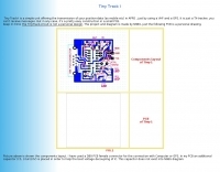 Amateur Packet Reporting System (APRS) operations often require compact, reliable solutions for transmitting position data, particularly for mobile or portable stations. This resource details the construction of the _Tiny Track-I_, a transmit-only APRS tracker designed for straightforward integration with a VHF radio and a Global Positioning System (GPS) receiver. It enables hams to broadcast their location without the complexity of a full-duplex TNC. The project outlines the printed circuit board (PCB) layout and schematic, based on an original design by N6BG, with a personal PCB drawing by SV1BSX. It includes specific component placement and notes an additional 10uF/10V capacitor (C5) for improved IC voltage decoupling, a modification not present in the original N6BG diagram. The unit connects to a computer or GPS via a DB9 female connector. This tracker is ideal for basic position reporting, offering a simple and effective way to participate in APRS networks. Its small footprint makes it suitable for vehicle installations or field deployments where space is limited, providing a **reliable 9600 baud** data stream for location updates.
 -
 The **Luis Trenker Award** is an amateur radio operating award established by the Amateur Radio Club Ladinia to honor the director and author Luis Trenker from Val Gardena, South Tyrol, Italy. To qualify for the award, HF stations must achieve five confirmed QSOs with each of five specific Alpine countries: Italy (with specific prefixes like I1, IK1, I2, I3, IN3, IW3, IV3), France, Germany (with DOKs A, C, T, U), Switzerland or Liechtenstein, and Austria (with prefixes OE2, OE3, OE6, OE7, OE8, OE9). A single QSO with a member of the Amateur Radio Club Ladinia can substitute for the five required Italian QSOs, with members' QSL cards bearing a special rubber stamp. VHF/UHF stations have a simpler requirement, needing only one confirmed QSO with each of the five Alpine countries. SWL stations are eligible under the same conditions as transmitting stations. All contacts must be valid after April 12, 1990. Applicants must submit a list of contacts, certified by two OMs or a club, to the Amateur Radio Club Ladinia in Ortisei, South Tyrol, Italy. The award manager is IN3PGS Karlheinz, and the club official is IW3AQL Luca.
 -
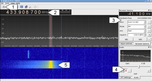 Analyzing 433 MHz radio signals from common wireless devices, such as temperature sensors and remote controls, involves understanding **On-Off Keying (OOK)** modulation. This resource details the process of capturing these signals using a Software Defined Radio (SDR) like Gqrx and then visually inspecting the captured audio data in a sound editor such as Audacity. It differentiates between **Pulse Width Modulation (PWM)** and Pulse Position Modulation (PPM) encoding schemes, illustrating how to identify and decode binary data by eye based on pulse and gap durations. The article provides a step-by-step walkthrough for decoding a wireless thermometer's data, correlating bit patterns with known temperature, humidity, and channel values. It also demonstrates decoding an RF remote control's button presses, highlighting the constant and varying parts of the transmitted packets. The content further introduces automated decoding using tools like RTL_433, explaining its capabilities in parsing various device protocols and showing how to interpret its output, including modulation type and decoded data. Specific examples include analyzing Prologue sensor protocol specifications from RTL_433's source code and noting common operating frequencies like 433.92 MHz in Europe and 915 MHz in the US.
 -
 High Speed Multimedia (HSMM) radio, as introduced by John Champa, K8OCL, represents a significant advancement in amateur radio's digital capabilities, moving beyond traditional keyboard modes like packet radio. This initiative, driven by ARRL's Technology Task Force, focuses on developing high-speed digital radio networks capable of up to 20 megabits per second. HSMM primarily facilitates digital voice (DV) and digital video (ADV), enabling real-time video transmission from emergency scenes to an EOC without expensive ATV gear, often requiring only a laptop, a PCMCIA card, a digital camera, and a small antenna. The working group's initial efforts concentrate on cultivating microwave skills within the amateur community to build and support portable and fixed high-speed radio-based local networking, or **RLANs**. These networks prove invaluable for RACES and ARES organizations, as well as homeland security and other emergency communications. Field Day exercises and simulated emergency tests (SETs) are encouraged to hone skills in rapid site surveys and deploying broadband HSMM microwave radio networks, with examples like linking Field Day logging stations or antenna test results at the Midwest VHF-UHF Society Picnic 2003. Getting started with HSMM often involves adapting off-the-shelf **IEEE 802.11** (WiFi) equipment to comply with amateur radio regulations, typically operating in the 2.4 GHz ISM bands. While consumer WiFi gear has range limitations under Part 15 rules, proper setup under amateur regulations can extend coverage significantly, with test networks like the Hinternet achieving 5-15 mile ranges at 54 M bit/s using small mast-mounted dish antennas. Careful selection of equipment with external antenna ports, high transmit power, and low receive sensitivity is crucial, along with using low-loss coaxial cable like LMR-400 for optimal performance at these frequencies.
 -
 Technical Comments about Transmitter Intermodulation, Distortion, and ESSB (or Hi Fi Wide Fi SSB) audio or over equalization by W8JI
 -
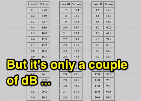 But it is only a couple of dB, The Effect Of Insertion Loss On Transmitted Power (dB to percentual loss) Original Information Provided by Neil McKie WA6KLA
 -
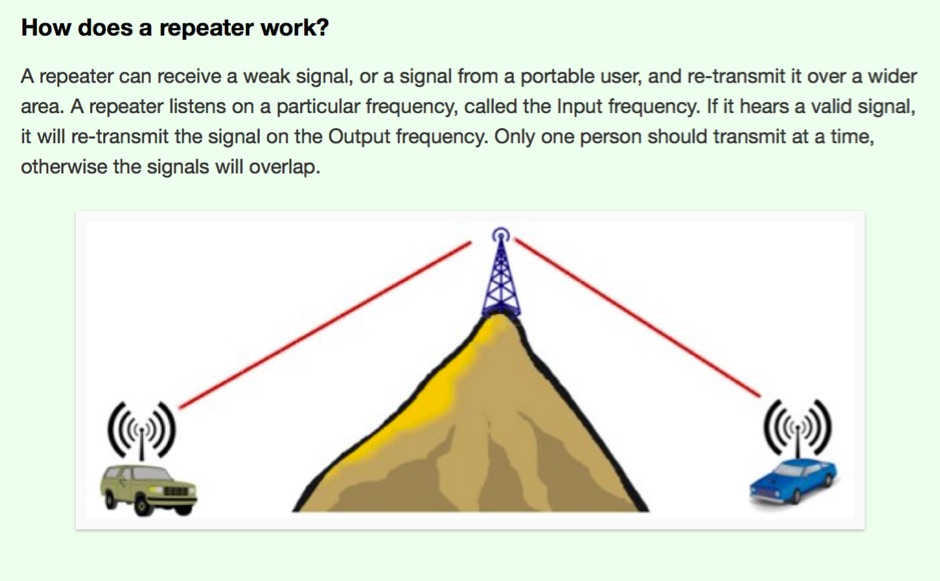 Amateur radio repeaters, often designated by an "R" number like _R6_ or _R5_, serve as crucial infrastructure for extending VHF/UHF communications range. This resource from Essex Ham explains the fundamental concept of a repeater, detailing how it receives on one frequency and simultaneously retransmits on another, typically with a 600 kHz offset for 2-meter repeaters. Understanding the input and output frequencies, along with the required CTCSS tone, is essential for successful access, ensuring your signal is processed and relayed across a wider service area. The article clarifies the importance of using the correct _CTCSS_ (Continuous Tone-Coded Squelch System) tone, often referred to as a sub-audible tone, to activate a specific repeater. It also touches upon the concept of _simplex_ operation versus repeater use, highlighting the benefits of repeaters for mobile and handheld transceivers. Proper operating procedures, such as listening before transmitting and keeping transmissions concise, are emphasized to maintain good amateur practice on shared repeater assets.
 -
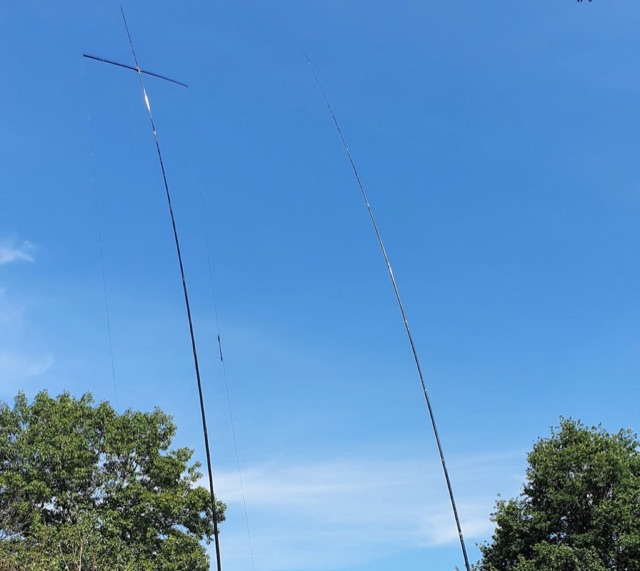 On the field comparison among C-Pole antenna, an EFHW vertical antenna and an Inverter V dipole antenna. Test is done using two identical WSPRLite beacons that transmit with 200mW on the WSPR frequency and analyzing spotted results.
 -
 Visualizes real-time amateur radio propagation spots using data from the PSK Reporter MQTT stream, providing immediate situational awareness for radio operators. The platform displays spots from various modes, including CW, WSPR, and JT65, in addition to the dominant FT8 digital protocol. FT8 Live focuses exclusively on live data streams, prioritizing current signal activity over historical archiving, which differentiates it from the official PSK Reporter map. A key feature is its integration with the Summits on the Air (SOTA) API, facilitating SOTA chasing by cross-referencing transmitting callsigns with SOTA alerts; a station is identified as an activator if the spot correlates with a scheduled alert within an eight-hour window. The user interface was developed by Arron (ZL1AN), with core data from Philip Gladstone (N1DQ), and stream delivery managed by Tom Stanton (M0LTE).
 -
 DL7JV shares his practical experience building and testing capacitive antennas, initially skeptical of their performance compared to magnetic loops and mono-band dipoles. His interest was piqued after hearing a Spanish station running 100 Watts on 80 meters with a 1-meter Micro Vert, making DX contacts into PY and UA0, despite the antenna being only 4 meters high in a garden. This prompted DL7JV to investigate further, consulting resources from DL7PE and DL7AHW, the latter providing DOS programs like "Mitspule.exe" and "Spulenprg.zip" for calculating antenna dimensions and coil conversions. The article outlines the construction of two prototype antennas: one for 7.050 MHz using a 75mm PVC pipe and another for 3.550 MHz with a 110mm PVC pipe. Both designs feature aluminum foil condensers and coils wound from 1mm² H07V-K wire. DL7JV provides specific measurements for the condenser capacitance, surface area, diameter, height, coil inductance, turns, and wire length for both 40m and 80m versions, along with RG58 feedline lengths. Initial reception tests for the 7 MHz antenna, placed indoors, yielded impressive S9+5 signals from a German station compared to an S8 from a 42-meter roof-mounted loop, even hearing a Japanese station. Transmission attempts on April 4, 2004, despite moderate solar storm conditions, resulted in successful QSOs on 7 MHz with EA5OT (579/559) and on 3.5 MHz with YT1NT (579/559) and G4KKI (579/559) using 100 Watts. DL7JV notes the antenna's sensitivity to coordination and feedline layout, suggesting a modification from DL7AXO involving a 500pF fixed capacitor and coil tap for improved SWR stability. He concludes that while the capacitive antenna is space-saving and performs well for reception and 100W transmission indoors, its transmit performance doesn't yet match larger antennas, with further outdoor field tests planned. DL7JV also intends to build a 1.8 MHz version.
 -
 Operating under the callsigns G1ORC, G4ORC, and M5ORC, the Oldham Amateur Radio Club (OARC) serves as a local hub for radio enthusiasts in Royton, Oldham, England. This RSGB-affiliated organization welcomes individuals with an interest in any facet of radio communication, fostering a community environment for learning and on-air activity. The club maintains an active calendar, detailing upcoming amateur radio events and specific courses hosted by OARC, providing a structured approach to engagement for its members. Club activities are centered at the No.1855 (Royton) Squadron Air Training Corps on Park Lane, a consistent meeting point for members. This physical location facilitates hands-on learning, equipment demonstrations, and social interaction among hams. OARC's commitment to the hobby is evident through its multiple transmitting licenses, enabling diverse operational experiences for its members across various bands and modes.
 -
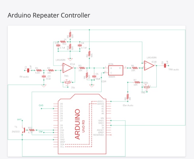 This blog article introduces an updated repeater controller project utilizing the Arduino UNO. It includes a CW identifier, and the ID message can be customized using hex codes. The author offers a Windows command line program for easier message coding and provides a link for download. The controller features three adjustable timers for IDer, Timer-out, and Squelch-tail. The article also mentions the use of an audio switch to control audio levels between the receiver and transmitter. Detailed instructions and code files are available on the author's website for both version 1 and version 2 of the Arduino repeater controller. The project aims to enhance repeater functionality and audio management in ham radio operations.
 -
 The Coulsdon Amateur Transmitting Society (CATS) website provides information on meeting schedules and an informational flyer. The content is concise and objective, catering to radio amateurs and technical users.
 -
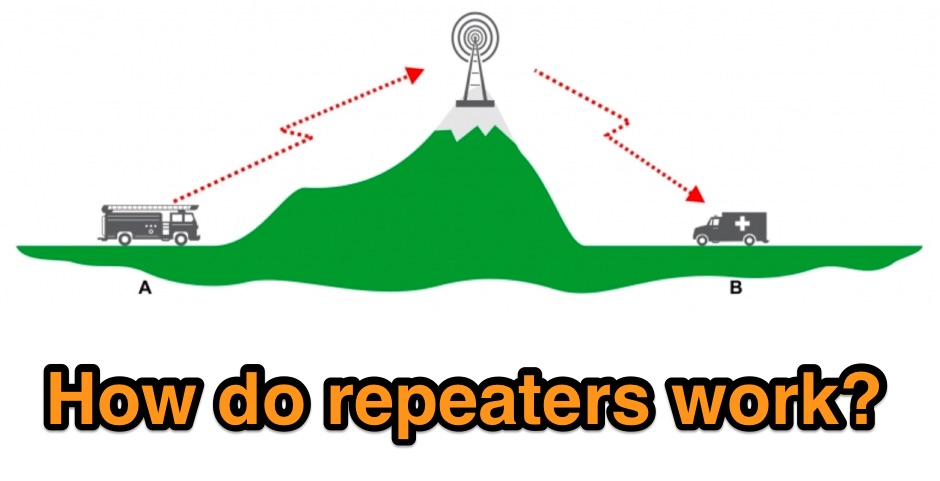 Illustrates the fundamental principles of radio repeaters, detailing their role in extending communication range beyond line-of-sight limitations. It begins by defining _simplex communication_ as a direct radio-to-radio link, effective only when no obstructions impede the signal path. The resource then introduces the concept of a repeater (or base station) strategically positioned on elevated terrain, such as a mountain, to overcome geographical barriers. The article clarifies the repeater's operational mechanism: it receives a signal on one frequency and simultaneously re-transmits it on a different frequency, enabling users on opposite sides of an obstruction to communicate. This _duplex operation_ is likened to satellite communication for VHF propagation, but with a fixed terrestrial station. Specific examples of signal paths are provided, showing how a handheld radio transmits up to the repeater, which then relays the message down to another user, effectively bypassing obstacles like hills or large buildings.
 -
 Identity of wwff/svff while having a qso with a svff expedition you are welcome to transmit also and two figures
 -
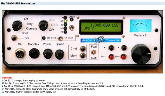 This transmitter covers the 160, 80, 40 and 20 metre bands and provides both SSB and properly generated CW. The CW side of this transmitter is not compromised and produces excellent CW. On SSB the audio has been tailored to provide a rising response to 3 KHz, with a sharp drop above that frequency. There is RF speech clipping to both provide more "punch" and to limit the peak output.
 -
 WB8LZR details the construction and initial field results of a multi-band vertical wire antenna, designed to complement his existing horizontal loop for improved DX on 80 meters. The antenna utilizes a 67-foot vertical wire, configured as a quarter-wave radiator on 80m, and employs a 1:1 current balun for RF isolation on 80m, 30m, and 17m. For bands like 40m, 20m, and 10m, where the wire acts as a half-wave or full-wave radiator, an additional impedance transforming _unun_ is integrated to manage the significantly higher feedpoint impedance and voltage. The author notes the vertical's performance as a receiving antenna, observing reduced noise compared to his main horizontal loop, particularly on 80m, and even hearing some long-path signals the loop missed. Initial QRP contacts, including a **1-watt** QSO with a _VP2 station_ on 30m, demonstrate its transmit capability. While the radial system is currently rudimentary, the project outlines practical considerations for multi-band vertical deployment and impedance matching.
 -
 The _G3TSO_ Mobile Antenna Page details construction and tuning methods for mobile antennas operating across **10 to 160 metres**. The content describes a Hustler-based design, optimized for RF performance and vehicle speeds, featuring centre loading. For optimal operation on various bands, the loading coil placement requires clearance from the vehicle body. Antenna resonance is critical for efficient mobile operation. A mobile antenna's base impedance may be as low as 27 ohms, requiring specific matching to achieve maximum radiation, as a minimum SWR at the transmitter does not always indicate resonance or maximum output. Tuning involves physical adjustment of antenna length to achieve resonance at the operating frequency. The _G3TSO_ page outlines a tuning procedure utilizing a low-power signal source and a field strength meter to identify maximum radiation before impedance matching. Loading coil placement, either at the base, center, or top of the antenna, influences radiation efficiency and mechanical stability for mobile installations. Centre-loaded whips, such as the Hustler design, offer a compromise between efficiency and stability, often for single-band operation. Helically wound antennas, including those for **28 MHz**, may present base impedances around 17 ohms, resulting in a 3:1 SWR at resonance. Low resistance grounding at the antenna base is also specified for optimizing performance and minimizing RFI during mobile operation. DXZone Focus: Mobile | Any | Antenna Tuning | HF
 -
 The video showcases the setup of a 300 MHz oscillator, a 100W radiofrequency amplifier, and a dipole antenna for transmitting radio waves, leading to the fluorescence of a nearby light bulb. It demonstrates the presence of standing waves on the dipole antenna and how intensity varies along its length. Additionally, the usage of a copper pipe as a receiving antenna is explored, showing changes in intensity depending on alignment and proximity to the transmitter. Finally, a B field antenna sensitive to magnetic fields is introduced, revealing brightness variations in different orientations. The video offers insightful observations on radio wave transmission and reception phenomena.
 -
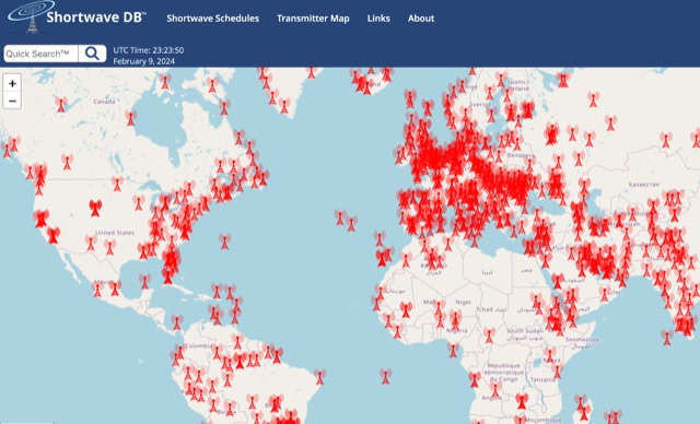 Worldwide Map of shortwave transmitters. Based on shortwave schedule database, this website let you serarch using filters for broadcasts schedule and at the same time to diplay the transmitter map.
 -
 This document details the construction, programming, and operation of a modular WSPR transmitter. The transmitter utilizes an ESP8266 NodeMCU, an SI5351 synthesizer with a TCXO for stability, and selectable low pass filters. Construction involves soldering headers, components, and assembling filter module. The ESP8266 is programmed via the Arduino IDE, requiring library installations and code modifications, including network credentials, callsign, and frequency . The transmitter is powered by USB or Vin terminals and its frequency is selected by jumpers and software settings. The document also covers FCC restrictions and how to use the WSPR network
 -
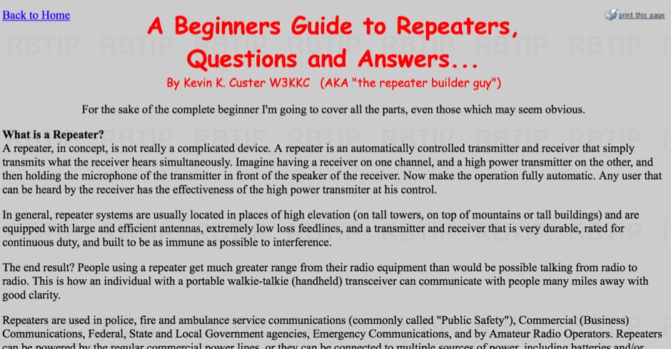 Explains the fundamental purpose of a repeater, detailing how these automated relay stations overcome distance and terrain limitations for VHF/UHF communications. It traces the historical development from early Bell Telephone Labs "relay" stations in 1922 to Art Gentry, W6MEP's, pioneering K6MYK amateur radio repeater in the mid-1950s, which remains active today. The resource clarifies the distinction between simplex and duplex operation, including the unique function of a "parrot repeater" for single-frequency recording and playback. Delving into the internal workings, the guide breaks down a repeater into its core components: the antenna system, feedline (often _Heliax_ or hardline for minimal loss), duplexer, receiver, transmitter, and controller. It emphasizes the critical role of the duplexer in preventing receiver desensitization by isolating transmit and receive signals, even with distinct frequencies. The discussion highlights the importance of high-performance, durable antennas and low-loss feedlines, citing examples of equipment installed in the 1960s and 1970s that are still in perfect working order. Operating a repeater is also covered, with an explanation of frequency offset (e.g., the 600 kHz standard for 2 meters) and the function of _CTCSS_ (PL tone) for access. It outlines standard input/output offsets for various bands, from 6 meters to 23 centimeters, while noting regional variations. The guide also touches on features like autopatch and Digital Voice Recorders (DVRs), providing a solid foundation for understanding repeater technology and usage.
 -
 Basic information on code plugs. What code plugs is, how to set up a code plug, transmit talk groups and configuring zones.
 -
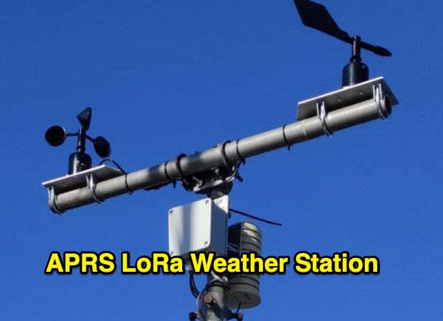 The weather station described here uses a TTGO v3 1.6.2 module and various sensors. It displays the data on an OLED screen and transmits them among a choice of protocols to the APRS, APRS-IS, Wunderground servers or via an MQTT broker. APRS data is transmitted on 433.775 MHz (can be changed) using the LoRa protocol. APRS beacons picked up by iGate gateways are then transmitted to APRS servers.
 -
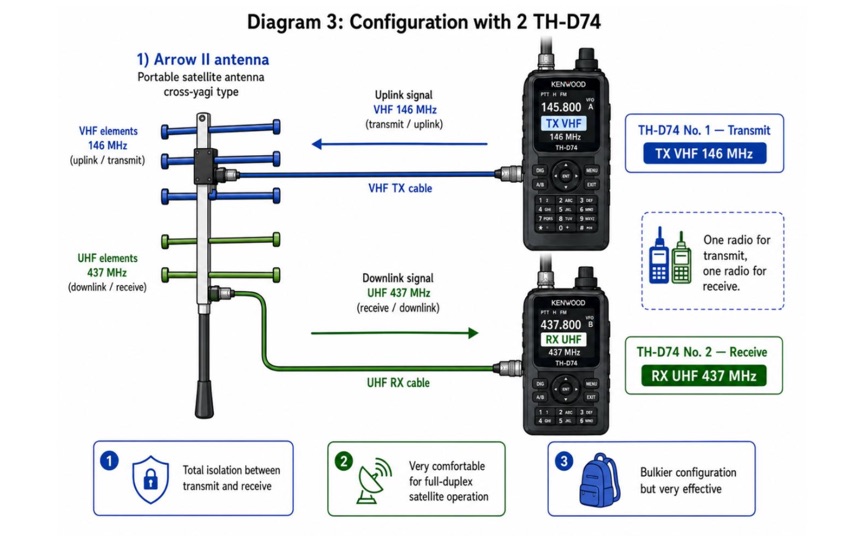 Examines current amateur radio satellite operations as of May 2026, providing a practical overview for hams interested in making their first satellite QSOs. The resource differentiates between Low Earth Orbit (LEO) satellites, such as the _ISS_, SO-50, RS-44, FO-29, AO-7, and GreenCube, and the geostationary QO-100. It highlights the distinct operational requirements for each, noting that LEO birds necessitate real-time tracking, antenna rotation, and Doppler compensation. The article emphasizes the critical practice of listening before transmitting and outlines methods for monitoring QO-100 in real time via the Goonhilly Earth Station WebSDR. It also covers tracking LEO satellites using tools like N2YO.com, Heavens-Above, and amsat.org/status. The author's experience with these platforms informs the guidance on equipment considerations and operating practices, ensuring hams understand the nuances of satellite communication in 2026, including the significant impact of QO-100 since its 2019 launch.
 -
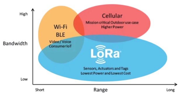 About LoRa, wireless communication technology designed to transmit data over long distances. LoRa provides a means for wireless data transmission over long distances with low power consumption. Practical applications of LoRa in amateur radio
 -
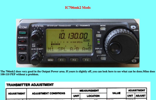 Presents two distinct hardware modifications for the Icom IC-7300 transceiver, detailing the necessary steps for each. The first modification, a _MARS_ transmit expansion, involves the physical removal of specific surface-mount diodes (D422) from the main board, enabling transmit capabilities across a broader frequency range, including out-of-band frequencies. It specifies the diode location on US versions of the IC-7300 and suggests using small diagonal cutters if a soldering iron is not preferred or available. The second modification focuses on the internal antenna tuner, aiming to provide wider impedance matching capabilities. This involves adding a **100k ohm** resistor to a designated point within the tuner circuit. The resource also briefly mentions a microphone modification for the _HM219_ and a general power increase, though without specific instructions for the latter two. It emphasizes safety precautions, such as disconnecting power and inspecting the work area.
 -
 The Slim Jim Antenna Calculator is an online tool that helps hams design a Slim Jim antenna for any desired frequency. This extended version of the J-Pole antenna design does not require a ground plane and is perfect for mounting inside PVC piping. The calculator determines the dimensions of the antenna elements based on the input frequency. Suitable for both receiving and transmitting purposes, this antenna can be easily constructed using common household wiring. The tool provides metric and imperial measurements, along with visual representations of the antenna design for easy reference.
 -
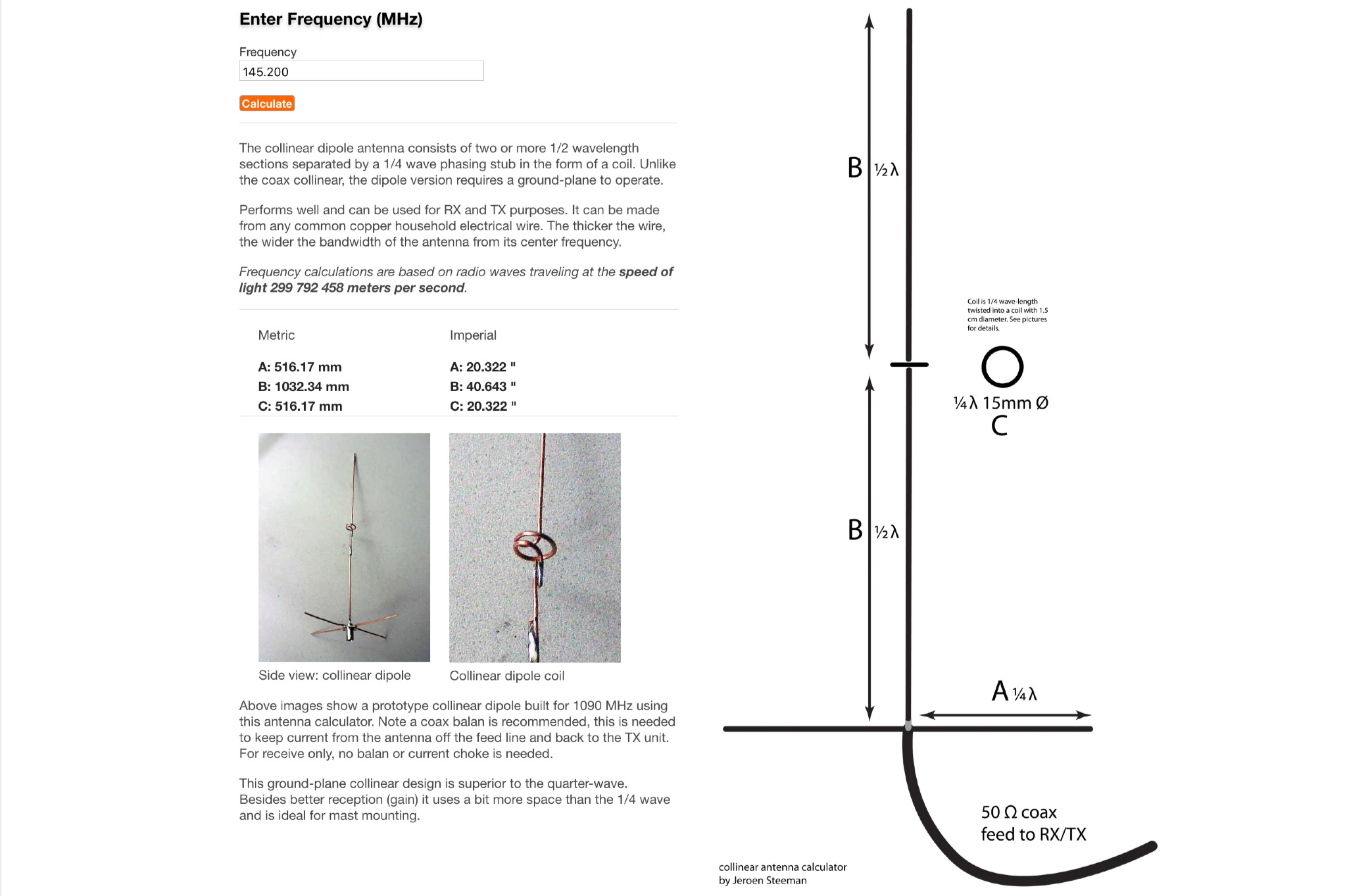 This page offers an online antenna designer to calculate the dimensions for a collinear dipole antenna at a specified frequency. The collinear dipole antenna is constructed with multiple 1/2 wavelength sections separated by a 1/4 wave phasing stub in the form of a coil. It requires a ground-plane to operate and can be used for both receiving and transmitting purposes. The antenna can be made from common copper wire, with thicker wire providing a wider bandwidth. The calculations are based on radio waves traveling at the speed of light. Ideal for ham radio operators looking to build their own antenna for improved reception and transmission.
 -
 Vertical antenna tests at the Sonten-Rancabali tea resort in Ciwidey, West Java. The assembly, led by Mr. Dian Kurniawan and the team, took just 20 minutes. Mrs. Mita performed the transmit check-in test, which was received across various regions in Indonesia, including Sulawesi, East Java, and Bangka Belitung. The team will release a video of the test soon and has thanked colleagues YB3HRY and YB0BAW for their reports.
 -
 The document details the construction and performance of a rotatable flag antenna designed for a small lot. The 7x14 feet flag, built with fiberglass poles and an aluminum hub, shows improved reception compared to the author's previous transmit antenna. Key components include a conventional transformer for impedance matching and a variable resistance termination system to optimize performance. Despite challenges like nearby objects affecting signal patterns, the antenna consistently provides better signal-to-noise ratios, making it a valuable addition for low-band listening in suburban areas.
 -
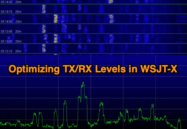 Exploring digital radio modes, the author rethinks how to adjust transmit and receive levels in WSJT-X. Despite effective communication using Yaesu's settings, a new procedure aims for better performance. For RX, set audio device levels to 100%, disable AGC, and adjust RF gain. For TX, enable "Remember power settings" and adjust power output to avoid ALC engagement. This method ensures reliable communication without signal degradation, enhancing dynamic range and minimizing noise.
 -
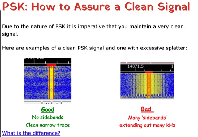 Due to the nature of PSK it is imperative that you maintain a very clean signal. In this page you will find examples of a clean PSK signal and one with excessive splatter, and a short guide on how to properly adjust your transmitter to assure a clean trace
 -
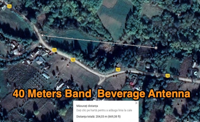 The author describes his experience building and using a Beverage antenna for the 40-meter band. Despite encountering some challenges, the antenna offered some improvements in receiving stations compared to a 3-element inverted Vee antenna. The Beverage antenna showed a significant daytime signal-to-noise ratio improvement and received signals better than the Vee antenna. However, the front-to-back ratio was not ideal, and the transmit power seemed to affect the Beverage antenna. Overall, the author concludes that the Beverage antenna might be more suitable for locations with higher noise levels. The total cost of the antenna was around 30 Euros.
 -
 This innovative antenna tuning unit (ATU) enables QRP operators to match their antennas without transmitting RF signals. Using a noise bridge technique instead of traditional transmit-and-tune methods, it achieves truly silent operation. The design incorporates an L-match network with switched inductors and variable capacitor, handling impedance matching from 3-30MHz. Operating from a 9V battery, it includes a built-in RF power meter and dummy load for QRP transmitter testing. The compact unit is particularly suitable for portable operations where minimal RF emissions during tuning are desired.
 -
 Ribbit is a novel digital text messaging mode for VHF/UHF communications for recreational and emergency use which radically increases the density of information transmitted by spectrum used. It leverages the computing power of the modern smartphone to increase the capabilities of any Handy Talkie without requiring any additional hardware or cable. A Ribbit message is fixed in duration at 1250 milliseconds. It is sent over audio modulation with a 2kHz bandwidth centered on 1.5kHz. It is preceded by 400ms of white noise to open analog squelch circuits.
 -
 Presents an interactive online **Moxon antenna designer** tool, enabling radio amateurs to configure and analyze lightweight Moxon antennas for HF and VHF bands. Users can specify design frequency, element lengths, wire diameter, insulation, and support height. The tool visualizes the antenna in interactive 3D graphics and generates comprehensive performance charts, including azimuth, elevation, 3D, and polarization radiation patterns, VSWR charts, antenna current diagrams, and Smith charts. It also allows selection of various ground types (e.g., very poor soil, salt water, free space) to model environmental effects on antenna performance. The designer provides insights into how physical dimensions and ground conditions influence key antenna parameters like forward gain, front-to-back ratio, and feed-point impedance, which is typically close to 50 ohms. It also includes a feature to model the effect of coaxial cable losses on **VSWR** at the transmitter end, distinguishing it from the feed-point VSWR. This helps operators understand the actual radiated power efficiency versus the apparent match at the transceiver, offering a practical perspective on antenna system performance in portable operations.
 -
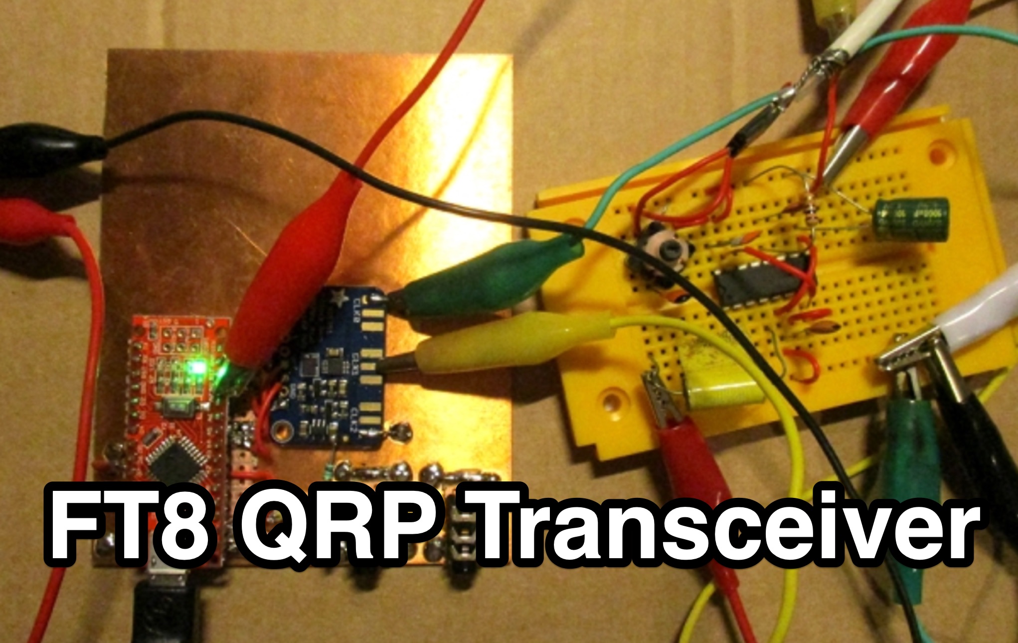 This page by Lajos Hoss, HA8HL, provides a detailed guide on how to build a simple direct receiver using FT8QRP CAT control support. The author shares his experience in making QSOs with FT8, WSPR, and JT65 modes during the Covid-19 lockdown. Modifications to the VFO, transmitter design using BD329 transistor Class A amplifier, and the challenges faced in achieving clean output signals within legal limits. This project is interesting for those hams that are interested in experimenting with DIY transmitter projects and understanding CAT control support for various amateur radio modes.
 -
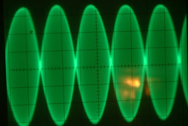 A simple 2-tone-generator for testing the linearity of SSB transmitters. This device is as simple as useful. With 2 transistors and an oscilloscope, it is fairly easy to test the linearity of your SSB transmitter. The 2-tone-method is a standardized test method that can be used to determine the maximum output and the amplification characteristics of a sideband transmitter.
 -
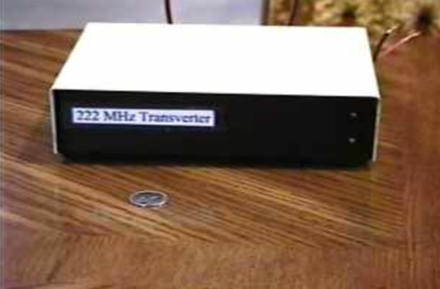 The 222 MHz Transverter project, based on Zack Lau's (W1VT) original July 1993 QEX magazine design, provides an IF of 28 MHz for both transmit and receive paths. Rick Bandla (VE3CVG) contributed supplemental notes and construction details, including modifications to achieve 10 mW output power from an initial 4 mW PEP. The design incorporates three distinct boards: a Local Oscillator (LO), a Transmitter (Tx), and a Receiver (Rx), with an estimated parts cost of just over $150 CDN, significantly less than commercial kits. Construction involves both through-hole and surface-mount components, with specific guidance on mounting MAV and MAR devices, grounding techniques, and component selection. The project details include parts lists, schematics for the LO, Tx, and Rx, and board layouts. Troubleshooting advice emphasizes sequential testing, starting with the LO, then Tx, and finally Rx, using a 194 MHz and 222.100 MHz capable FM handheld for signal tracing. Further enhancements are discussed, such as an optional Tx driver stage to boost output to 100 mW and the potential modification of a Motorola Maxor 80 PA for 222 MHz SSB/CW operation. The resource also covers practical aspects like power attenuation pads for IF radios (e.g., FT817) and considerations for enclosure design, including repurposing a Maxor 80 case. Performance reports indicate successful 70 km contacts with only 4 mW output.
 -
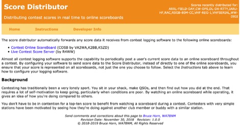 The Score Distributor facilitates real-time score forwarding for amateur radio contests, automatically transmitting data from various logging software to multiple online scoreboards. By configuring logging applications to send score data to the Distributor, operators ensure their current score is simultaneously represented on platforms like the _Contest Online ScoreBoard_ (COSB) and the Live Contest Score Server by R4WW. This system eliminates the need to choose a single scoreboard, providing broader visibility for participants. This utility enhances the competitive experience by allowing contesters to monitor their performance against other stations throughout an event. Observing real-time standings can provide significant motivation, particularly during periods of challenging propagation or when striving to maintain pace with club members or peers. The platform supports almost all major contest logging software, simplifying integration for a wide range of operators. Developed by WA7BNM, the Score Distributor was last revised on June 14, 2023. It aggregates score data, offering a unified point of submission that then disseminates the information, ensuring a **single point of entry** for broad scoreboard coverage and improving the dynamic feedback loop for participants.
 -
 A homebrew spectrum analyzer, the Specan, provides a crucial measurement capability often missing from the typical amateur radio shack, allowing for detailed analysis of RF signals up to 70 MHz. This double-conversion superheterodyne receiver design incorporates 112 MHz and 12 MHz intermediate frequencies, utilizing an _Si570_ as the local oscillator for fine tuning down to 1 Hz steps. It offers two resolution bandwidths: 300 KHz for broad spectrum sweeps and 1 KHz for precise close-in distortion measurements, achieving an 80 dB spur-free dynamic range at 1 KHz resolution. The project, a reboot of the classic _W7ZOI/K7TAU_ design from November 1998 QST, integrates an _Arduino_ microcontroller for controlling the Si570, managing a front-panel LCD, and communicating with a PC for spectrum plotting. This approach significantly reduces cost compared to commercial units, making advanced RF diagnostics accessible to homebrewers. The Specan can measure carrier suppression, VFO cleanliness, antenna VSWR, transmitter harmonics, and filter passband shapes, providing insights beyond what an oscilloscope or frequency counter can offer. Construction emphasizes modularity and careful shielding, with each stage built and tested individually on unetched copper clad board. The design includes detailed instructions for integrating the Arduino, building the Si570 oscillator, and aligning the various modules, often using the Specan itself for calibration. It requires a well-regulated linear power supply and can be built with common tools and readily available components, making it a practical and rewarding endeavor for those looking to enhance their RF test bench.