Search results
Query: 80 m band
Links: 336 | Categories: 5
-
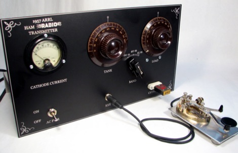
 W/VE amateurs work as many amateur stations in as many DXCC countries of the world as possible on 160, 80, 40, 20, 15, and 10 meter bands. Foreign amateurs (also including KH6, KL7, CY9, and CYØ) work as many W/VE stations in as many of the 48 contiguous states and provinces as possible.
 -
 The _Sci.Electronics FAQ: Repair: RFI/EMI Info_ document, authored by Daniel 9V1ZV, provides a detailed analysis of computer-generated RFI/EMI, focusing on its impact on radio reception. It identifies common RFI sources such as CPU clock rates (e.g., 4.77 MHz to 80 MHz), video card oscillators (e.g., 14.316 MHz), and even keyboard microprocessors, all of which generate square-wave harmonics across HF and L-VHF regions. The resource outlines a systematic procedure for pinpointing RFI origins, including disconnecting peripherals and using a portable AM/SW receiver with a ferrite rod antenna to localize strong interference sources. The document categorizes RFI mitigation into shielding, filtering, and design problems, offering practical solutions for each. It recommends applying conductive sprays like _EMI-LAC_ or _EMV-LACK_ to plastic casings of radios, monitors, and CPUs to create effective Faraday cages, emphasizing proper grounding and avoiding short circuits. For filtering, the guide suggests using line filters, ferrite beads, and toroids on power and data lines, and small value capacitors (e.g., 0.01 uF for serial/parallel, 100 pF for video) to shunt RFI to ground. It also discusses the use of bandpass, high-pass, low-pass, and notch filters on the receiver front-end or antenna feed to combat specific in-band noise.
 -
 A dual band portable inverted V antenna for 80 and 40 meters band with dimensions for other bands and several assembling instruction
 -
 An interesting presentation of a real multiband Fan Dipole antenna, optimized for better DX operation performances, considering the terrain, position, DX destination path and other influencing factors
 -
 A 600W 1.8 MHz to 54 MHz power linear amplifier made using rugged MRF300 transistors featuring output power between 580W and 750W depending on band, power supply: 48V, 18A typical, 20A max
 -
 This online project guide details the construction of a homebrew boom microphone system. It details the assembly of a microphone shell from a 3/4" PVC pipe section and an end cap, requiring a drilled hole for a snug fit of the electret or condenser mic element. The internal wiring schematic specifies a **2.2 K** resistor and a **47 uF** polar capacitor for signal conditioning, with a circuit diagram provided for integration with IC-706 series transceivers. The guide outlines the use of CAT-5 cable for internal connections, incorporating strain relief at the rear of the mic shell, and an inline 3.5 mm jack to facilitate an external _PTT_ line, designed for a foot-mounted switch. Further construction involves fabricating a microphone shock mount from a 2-inch PVC connector, detailing the creation of four "fingers" and the insertion of screw-eyes for attaching elastic bands, which are twisted 180 degrees for tensioning and vibration isolation. A foam wind screen is also incorporated into the microphone assembly, secured with adhesive. The boom arm itself is repurposed from an articulated architect lamp, with the original lamp assembly converted into a **60 watt** resistive load for testing power sources. Microphone cabling is secured to the boom arm using wire ties, ensuring sufficient slack at hinge points to maintain articulation. The boom base is mounted to a bookshelf, requiring specific positioning to achieve proper microphone placement in front of the operator. Performance evaluation of the microphone system is conducted through on-air audio signal reports from other amateur radio operators. DXZone Focus: Online Project Guide | Boom Microphone Construction | Electret Mic Element | PTT Line
 -
 The 160-meter amateur radio band, spanning 1.8 to 2 MHz, was historically the lowest frequency amateur allocation until the introduction of the 630-meter and 2200-meter bands. ITU Region 1 allocates 1.81–2 MHz, while other regions use 1.8–2 MHz. This band, often called "Top Band" or "Gentleman's Band," was established by the International Radiotelegraph Conference in Washington, D.C., on October 4, 1927, with an initial allocation of 1.715–2 MHz. Effective operation on 160 meters presents significant challenges due to the large antenna sizes required; a quarter-wavelength monopole is over 130 feet, and horizontal dipoles need similar heights. Propagation is typically local during the day, but long-distance contacts are common at night, especially around sunrise and sunset, and during solar minimums. The band experienced a resurgence after the LORAN-A system was phased out in North America in December 1980, leading to the removal of power restrictions.
 -
 The BTech DMR-6X2 dual-band DMR handheld radio is thoroughly reviewed, detailing its features and performance for amateur radio operators. This resource covers the radio's capabilities for both VHF and UHF frequencies, supporting Tier II DMR digital and FM analog modes. It highlights key specifications such as its **136-174 MHz** and **400-480 MHz** frequency ranges, CTCSS/DCS, DTMF, 2-TONE, and 5-TONE signaling, and its _digital simplex repeater_ function. The review provides a comprehensive unboxing experience, listing included accessories like two Li-Ion batteries (2100 and 3100 mAh), a programming cable, and a 37-page English user guide. It also specifies the radio's physical dimensions of 5.1 x 2.4 x 1.5 inches and weights of 9.9 oz with the 2100 mAh battery and 10.8 oz with the 3100 mAh battery, offering practical insights for hams considering this transceiver.
 -
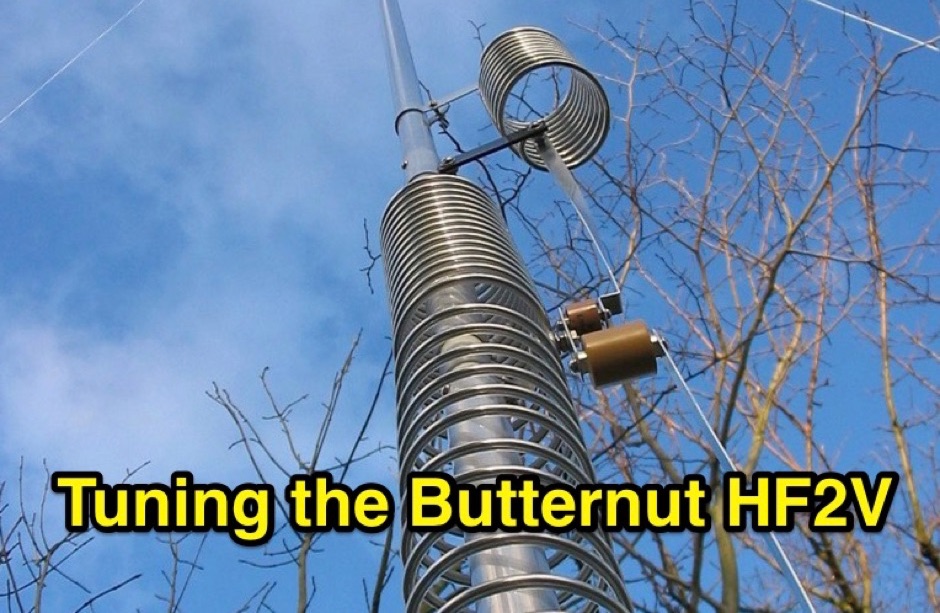 Complete instructions on tuning the Butternut HF2V on four bands, 80, 40 , 30 and 15 meters
 -
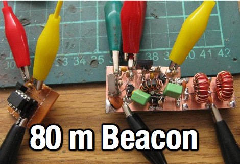 An home made CW beacon transmitter project running 1.5 W on the 80 meters band
 -
 An easy to build and extremely high performance antenna, works perfectly on all HF bands 3.5-28 MHz with some compromises, it is basically an half wave dipole for 40-80 meters, an LC circuit or trap 40 meters allows you to use a single radiating element.
 -
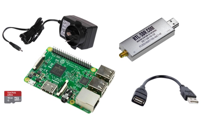 This project is a Software Defined Radio Receiver. It has a frequency range of 24MHz 1.2GHz. It can demodulate AM, FM, USB, LSB with selectable bandwidths of 600, 2400, 2800, 3200 and 6400Hz. Using a simple RTL-SDR Dongle and Raspberry Pi 3 computer using GNU RADIO
 -
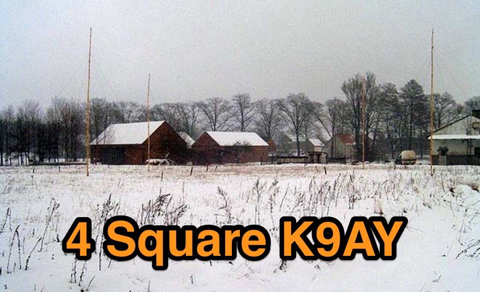 4 Square K9AY Array project for 80 and 40 meters band
 -
 Setting up a ZZ Wave antenna, a dual band loop antenna covering 80 and 40 meters.
 -
 The antenna in this project is a modification of the techniques used to design a multiband fan type dipole with little or no tuning involved having a total space of 105 feet
 -
 The CQ World Wide DX Contest records page details the highest scores achieved in the CQ WW DX Contest across various categories and years. It systematically lists records for both SSB and CW modes, segmenting results by entry class such as Multi-Multi, Multi-Two, Multi-Single High, Multi-Single Low, Single Operator High Power, Single Operator Low Power, Single Operator QRP, Single Operator Assisted High, Single Operator Assisted Low, and Single Operator Assisted QRP. Each record entry specifies the callsign, the operator's callsign in parentheses if different, the year of operation, and the total score achieved. The data is further broken down by individual amateur radio bands, including 160m, 80m, 40m, 20m, 15m, and 10m, allowing for granular analysis of performance within specific frequency segments. The page also includes records for the "ALL" band category, representing cumulative scores across all operational bands. The presented records span from 1948 to 2025, providing a historical perspective on contest performance. This resource also references other CQ contests like CQ WPX, CQ WW RTTY, CQ WPX RTTY, CQ 160, CQ VHF, and WW DIGI, indicating a broader context of contest record keeping. It explicitly states that late logs are not included in the records, ensuring data integrity. The page is maintained by the World Wide Radio Operators Foundation, Inc.
 -
 Isotron antennas are antennas of reduced size, without tuning. On 40 and 80m band, it is made of two plates into v whose angles are connected by a coil. In this article the description of a home made realization for the 40m band.
 -
 The CQ World Wide DX Contest records document top scores, with the Multi-Multi SSB category showing CN8WW achieving **78,170,508 points** in 2000. These records span from 1948 to 2025, categorizing results by region, operating class (e.g., Single Operator High Power, Low Power, QRP, Assisted), and specific bands like 10M, 15M, 20M, 40M, 80M, and 160M. For instance, EF8R (E77DX) holds the All-Band High Power SSB record with **25,747,775 points** in 2025. Each entry includes the callsign (with operator callsign in parentheses for guest ops), year of operation, and total score. The _CQ WW DX Contest_ also features records for the RTTY and VHF contests, alongside the main SSB and CW categories. QRP records demonstrate significant achievements, such as P40W (W2GD) with 5,097,780 points in the All-Band SSB QRP category in 2000. Multi-Two and Multi-Single categories are also detailed, providing a comprehensive overview of competitive performance.
 -
 A dual band dipole antenna for 40 and 80 meters band. Total lenght of 26 meters, foreseen two coils at aprox 11 meters distance from center feed.
 -
 Fifty-three digital modes, including PSK31, RTTY, and JT65, are explored in this resource, providing detailed descriptions of their underlying technologies and typical use cases. It covers error correction methods like ARQ in PACTOR and FEC in JT65, alongside modulation schemes such as FSK and PSK. The content highlights the evolution of digital communication from traditional TNC-based systems to modern sound card implementations, emphasizing the role of personal computers in advancing these modes. Specific modes like AMTOR, PACTOR, and G-TOR are discussed, noting their baud rates and error correction capabilities. For instance, AMTOR operates at 100 baud, while PACTOR offers 200 baud with Huffman compression. The article also delves into newer modes like MFSK16, which uses 16 tones and continuous Forward Error Correction, and Olivia, capable of decoding signals 10-14 dB below the noise floor. Each mode's bandwidth, speed, and resilience to propagation challenges are examined, such as MT63's 1 KHz bandwidth and 100 WPM rate, or Hellschreiber's 75 Hz bandwidth and 35 WPM text rate. The resource also lists predominant USA HF digital frequencies for bands like 160, 80, and 40 meters, specifying segments for PSK31, RTTY, SSTV, and Packet. It includes links to freeware and shareware sound card software such as Digipan, FLDigi, and MixW, enabling amateurs to experiment with these modes.
 -
-
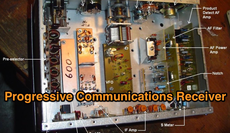 The purpose of this webpage is to document an attempt at this project starting with the 80m core receiver first and also having the parts on hand for then adding the first dual conversion band (40m)
 -
 Documents the OC1I and OC6I IOTA DXpeditions to Peru, specifically highlighting operations from SA-098 (Isla La Leona) and SA-076 (Isla Lobos de Afuera). The OC1I team logged over **8000 QSOs** from SA-076, while OC6I made 1400 QSOs from SA-098, despite challenging propagation conditions. The resource details the equipment used, including an _IC-7000_, an IC-706mkIIG, and a TS-440SAT, along with various antennas such as a 160m dipole, FD4, G5RV, and a multi-band vertical for 17m, 20m, 30m, and 40m. The DXpedition dates are specified: OC6I operated from SA-098 between December 28 and December 30, while OC1I was active from SA-076 from January 2 to January 7. Both operations are confirmed as valid for IOTA credit. The page also includes a video link for the OC6I operation and a photo gallery from the DXpedition. Feedback is welcomed, and the webmaster is identified as Bodo Fritsche, DL3OCH.
 -
 Full article on how to build a home-made wire dipole antenna for 40 and 80 meters band. Article is fully in italian, as it was published on ARI RadioRivista, but is plenty of self explaining pictures that will guide you on homebrewing this trapped dipole antenna for the lower amateur radio bands.
 -
 An antenna for 80 meters band for those who does not have enough space to setup a halwave wire dipole that is aprox 130ft or 40 meters. The antenna is an open-wire-fed shortened dipole
 -
 An inverted V Dipole antenna for HF bands, working on 10 20 40 and 80 meters band. PDF Presentation
 -
 The 2200-meter band (135.7-137.8 kHz) presents unique challenges for amateur radio operators due to its narrow 2.1 kHz bandwidth, low signal levels, and high noise. W1TAG explores various transmission modes suited for this demanding environment, highlighting that traditional voice modes like SSB and AM are impractical. Plain old CW serves as the baseline, demonstrating effectiveness across different modes, though signal-to-noise ratio (SNR) significantly limits practical speeds. The article notes that reducing CW speed below 5 WPM can improve copy, especially with computer-aided spectrum analysis software capable of decoding signals too weak for human ear reception. QRSS, or "CW sent slowly enough that speeds are best expressed in seconds per dot," is a key mode for LF work, with examples ranging from 3 seconds/dot to extreme 240 seconds/dot transmissions. _Argo_ by I2PHD is mentioned as a simple program for QRSS, enabling reception of signals like BRO, a Part 15 beacon, at a distance of **1100 miles**. Other modes discussed include Dual Frequency CW (DFCW), which uses frequency shifts to distinguish dots and dashes, and Binary Phase Shift Keying (BPSK), a phase modulation technique employing 0 to 180-degree phase flips. WOLF (Weak-signal Operation on Low Frequency), a specialized BPSK form by KK7KA, encodes 15-character messages into 960-bit packages, taking 96 seconds to transmit, and has demonstrated successful reception over **672 seconds** for a message from a 1-watt beacon. Further modes include PSK, FSK variations like JASON and MSK, and graphical modes such as Hellschreiber and Chirped Hell. The article concludes with a practical chart comparing the time required to send a simple message like "WD2XES FN42CH " across these diverse LF modes, offering valuable insights for operators planning contacts on the low bands.
 -
 The VU2BBB repeater, located in Matheran, Maharashtra, commenced operations in the late 1980s, a significant undertaking by the Bombay Repeater Society. This repeater facilitates VHF and UHF communications for local amateur radio operators, providing extended range and improved signal reliability across challenging terrain. Its establishment marked a key development in regional amateur radio infrastructure, offering a crucial node for local nets and general QSO traffic. The repeater's operational parameters include specific input and output frequencies within the 2-meter band, typically utilizing a standard offset. CTCSS tones are often employed to mitigate interference and ensure selective access for authorized users, a common practice for repeaters in densely populated areas. Regular maintenance and upgrades ensure _VU2BBB_ remains a reliable asset for the amateur community, supporting emergency communications and daily amateur radio activities. The _Bombay Repeater Society_ continues to oversee its operation, reflecting a sustained commitment to local ham radio services.
 -
 Over 1900 ARISS school events have been conducted since 2000, facilitating amateur radio contacts between students and ISS crew members. This resource details the Amateur Radio on the International Space Station (ARISS) program, outlining scheduled contacts, operational procedures, and application processes for educational institutions worldwide. It lists specific upcoming contacts, such as those with Lewis Center for Educational Research in California and Vauban, Ecole et Lycée français de Luxembourg, typically operating on a 145.800 MHz downlink frequency. The content also provides crucial guidelines for radio amateurs, emphasizing the importance of not interfering with scheduled school contacts and utilizing the crossband repeater for general QSOs when available. It clarifies crew availability for casual contacts, noting that astronauts are usually free during personal time, approximately one hour after waking and one hour before sleeping, and often on weekends. Constraints on scheduling, such as avoiding EVA weeks and specific crew rest periods, are also detailed. Furthermore, the resource includes historical statistics on direct versus telebridge contacts, QSL information, and links to related ARISS, AMSAT, ARRL, and NASA websites. It also provides information on applying to host an ARISS contact for schools and youth organizations in various regions, including the United States, Europe, Africa, the Middle East, Canada, Central and South America, Asia, and Australia.
 -
 A multi band antenna for HF band capable to operate from 10 to 80 meters band depending on wire lenght loaded with a small inductance neat the feed end.
 -
 Amateur radio antennas manufacturer based in Italy. Produces HF end-fed, dipoles, and other wire antenna types, mono band and multi band antennas.
 -
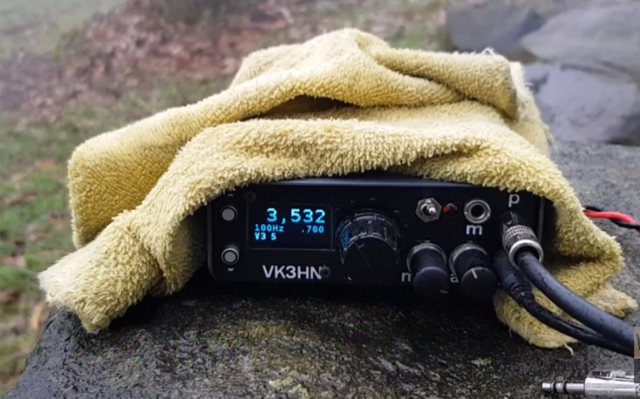 Summit Prowler 6 is a pocket-sized SSB/CW transceiver for 80, 40, 30 and 20m
 -
 A trap antenna dipole covering two differen bands made reusing an old 160/80m inverted vee antenna.
 -
 A homebrew radio transmitter project, based and inspired by the original 30 Watts input on 80 50 and 15 meters band transmitter by W11CP
 -

-
 A loop antenna for 80 and 40 meters band, the main loop is based by a crossed line using aluminium strip lines. The main loop diameter is 150 cm.
 -
 Designing and constructing a two-element receiving loop antenna array for HF operation involves specific considerations for achieving high directivity and noise reduction. This resource details a homebrew system comprising two 30-inch diamond-shaped loops, spaced 20 feet apart, which are fed through mast-mounted preamplifiers and passive signal combiners. The operational principle relies on adjusting phase delays between elements via precise _Belden 8241_ coaxial cable lengths, optimized for specific bands from 160m to 20m. Performance data, derived from _EZ-NEC_ modeling, illustrates consistent 90° azimuth-plane beamwidth and low take-off angles across the target bands, with _Receiving Directivity Factor_ (RDF) values comparable to a 300-foot Beverage antenna. The article presents detailed elevation and azimuth plots for 20m, 30m, 40m, 80m, and 160m, demonstrating the array's ability to provide strong response at low DX angles while also supporting _NVIS_ signals. Key components like the _DX Engineering RPA-1_ preamplifier and _DXE RSC-2_ signal combiner are discussed, alongside the importance of impedance matching to preserve antenna patterns. The construction emphasizes self-contained elements that do not require ground radials, offering a compact solution suitable for suburban environments and stealth installations, with a focus on optimizing receive performance independently from transmit antennas.
 -
 A simple portable dipole antenna for the 40 meter band using a total lenght of 18 meter. It can be used for 80 to 10 meters coverage using a antenna tuner.
 -
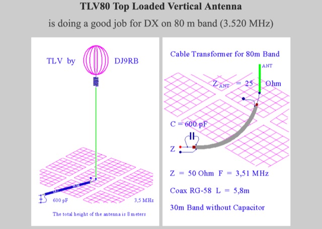 TLV80 is model of a Top Loaded Vertical Antenna is doing a good job for DX on 80 m band. A version for 80m-30m is provided.
 -
 The ZS1J/B beacon operates on 28.2025 MHz with 5 Watts output to a half-wave, end-fed vertical antenna, initially installed in 1977 as ZS5VHF near Durban. The 10-meter transmitter is a modified 23-channel CB radio, and the identification keyer uses a diode matrix unit with TTL ICs from the same era. After relocation to Plettenberg Bay in 1993, the beacon has been in continuous service, with additional QRP transmitters later installed for other bands. In 1994, a single-transistor, 80-meter, 0.5-watt QRP transmitter with a half-wave dipole was added on 3586 kHz, followed by a 160-meter, 0.5-watt unit on 1817 kHz. A 30-meter, 0.5-watt transmitter was installed in 1996, operating on 10.124 MHz. In 2002, a 40-meter QRRP beacon on 7029 kHz, with an output of 100 microwatts, achieved DX reports up to 1100 km from ZS6UT in Pretoria. Best DX reports for the 80m and 160m beacons came from 9J2BO.
 -
 One of the featured products, the V350 CAMP, is a multiband vertical antenna covering 6 to 80 meters, priced at R$ 799,90, demonstrating the range of ready-to-use solutions available. The inventory includes various antenna types such as **HF**, **VHF**, and **UHF** designs, along with dual-band options like the J-Pole Dual V/UHF for R$ 235,00. For those building their own arrays, the store stocks essential components like element holders, clamps, junction boxes, and aluminum plates, alongside specialized items such as the KIT Isolador Central Dipolo - 01DX for R$ 99,90. The shop also provides a comprehensive selection of installation hardware, including diverse antenna mounts, PTT supports, and various coaxial cables like RG58 and RG213, with prices up to R$ 849,90 for RG213. Connectors such as UHF male PL259 and various adapters are readily available, ensuring compatibility for different setups. Additionally, specialized items like side handles for popular transceivers such as the FT857/891 and IC7300 are offered, catering to specific equipment needs. Beyond antennas, the store supplies practical accessories like transport bags, 12V power cables for transceivers, and even branded merchandise like the Antena Kit mug. Rodrigo Gonçalves, PP5BT, manages the operation from Blumenau, SC, Brazil, providing direct contact via WhatsApp at +55 47 9.9985.0155.
 -
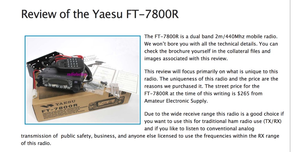 Yaesu FT-7800R dual band 2m/440Mhz mobile radio review
 -
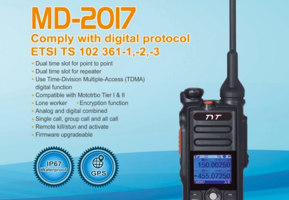 The MD-2017 is a dual band DMR and Analog handheld transceiver with a frequency range on VHF 136-174 MHz and on UHF 400-480 MHz
 -
 Low-frequency (LF) radio time signals, operating primarily in the 40–80 kHz range, are broadcast by national physics laboratories for precise clock synchronization. Transmitters like **JJY** (40 kHz, 50 kW; 60 kHz, 50 kW), RTZ (50 kHz, 10 kW ERP), MSF (60 kHz, 15 kW ERP), WWVB (60 kHz, 50 kW ERP), RBU (66.66 kHz, 10 kW), and DCF77 (77.5 kHz, 50 kW) cover vast geographic areas, often several hundred to thousands of kilometers. LF signals offer distinct propagation advantages over higher-band transmissions such as GPS. Their long wavelengths (3–6 km) enable effective diffraction around obstacles like mountains and buildings. The ionosphere and ground act as a waveguide, eliminating the need for line-of-sight and allowing a single powerful station to cover extensive regions. Ground wave propagation minimizes ionospheric variability effects on transmission delay, and signals penetrate most building walls effectively. Robust and low-cost receivers, often priced at 20–30 USD/EUR, are widely used in radio clocks. These receivers typically comprise a tuned ferrite core antenna, a receiver IC (e.g., Atmel T4227, U4223B, MAS1016) for amplification and AM detection, and a microcontroller for decoding the time signal and phase-locking a local clock. Specific components for DCF77, MSF, and WWVB are readily available from vendors like HKW Elektronik and Ultralink.
 -
 The PG7V Contest Calendar provides a curated listing of significant **HF contests**, with a particular focus on events relevant to European amateur radio operators. It details contest specifics such as start and end times in UTC, eligible bands (e.g., 80 meters, 40 meters, 10 meters), and required exchange information (e.g., serial number, CQ-zone, DOK, locator, age). The calendar includes diverse modes like CW, SSB, PSK63, RTTY, and FT4, catering to various operating preferences. Featured contests include the RSGB 80m Club Championship, WW WPX Contest, IARU Region 1 Fieldday, and ARRL International Digital Contest. Each entry links directly to the official contest rules for detailed information. The calendar also notes specific participation rules, such as the 1 KHz QSY requirement in the HA3NS Memorial Contest or the 24-hour single-operator time limit in the ARRL International Digital Contest. This resource is updated regularly, ensuring timely information for upcoming **contest operations** over a four-week period. It serves as a practical tool for hams planning their contest activity.
 -
 A portable operation experience with a SpiderBeam pole during a contest, testing wire antennas, like dipole and delta loops configurations on 20 40 and 80 meters band.
 -
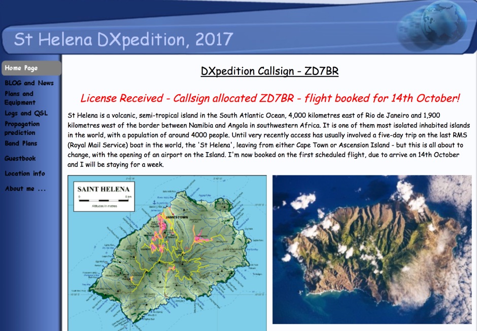 DX Pedition to St Helena 10-80 meters bands SSB RTTY FT8 CW by G0VDE
 -
 The Baofeng UV-5R handheld transceiver, introduced around 2012, operates across the 2-meter (144-148 MHz) and 70-centimeter (420-450 MHz) amateur bands, offering dual-band receive and transmit capabilities. This review provides an early assessment of the radio's form factor, user interface, and general performance, noting its compact size and the inclusion of a **VFO/Memory mode** button for frequency management. The device supports both FM and narrow FM modes, with a reported power output of 4 watts on VHF and 3 watts on UHF, making it suitable for local simplex and repeater operations. Key features discussed include its 128-channel memory capacity, a built-in VOX function, and a **DTMF keypad** for tone dialing and repeater access. The review highlights the radio's ability to scan frequencies and memories, along with a dual-watch function allowing simultaneous monitoring of two frequencies. Battery life is addressed, with the standard 1800 mAh Li-ion pack providing several hours of operation depending on transmit usage. Initial impressions cover the radio's construction and the clarity of its LCD display, which shows both A and B band frequencies.
 -
 Thsi article describes a microcontroller driven semi-automatic antenna tuner capable of handling power levels up to 150 watts. The device is a low pass filter tuner manually tuned by setting the optimized L/C combination by hand and then storing the values into the EEPROM of the mictrocontroller to recall them later (seperately for each band from 80 to 10 meters including WARC bands)
 -
 The Buddistick antenna, as demonstrated by KP4MD, effectively handles up to **250 watts** and provides coverage from 40 through 10 meters, with an optional coil extending operation to 80 and 60 meters. KP4MD's video presentation meticulously describes the antenna setup, emphasizing the critical role of the _shunting coil_ for achieving resonance on lower bands like 40 and 80 meters. This practical approach highlights how a compact antenna can deliver solid performance from a constrained location. SWR curve diagrams are included, clearly illustrating the impact of the shunting coil on the antenna's resonating frequency. These visual aids provide concrete evidence of the adjustments needed for optimal operation across different bands, particularly when space is at a premium. KP4MD's insights are particularly valuable for hams operating from apartments or other limited spaces, showcasing real-world results from a balcony installation.