Search results
Query: common
Links: 356 | Categories: 5
-
 Group of Amateur Radio operators, generally from the Yavapai County area in Arizona, who share common interests, goals, and aspirations.
 -
 Sixty-meter repeaters typically use a 1 MHz frequency separation between input and output, while 2-meter repeaters commonly employ a **600 kHz** split and 70-centimeter repeaters use a **5 MHz** offset. This article details the fundamental technical principles of amateur voice repeaters, explaining how they extend VHF/UHF communication range by receiving on one frequency and simultaneously retransmitting on another. It covers essential components such as receivers, transmitters, filters, and antennas, often situated on elevated locations for optimal coverage. The resource delves into the critical challenge of _desensing_—where the repeater's strong transmit signal overpowers its own receiver—and the engineering solutions employed, including antenna separation and the use of high-Q cavity filters. It also explores various control and timing systems, from basic squelch activation to more sophisticated microcontroller-based boards that manage functions like voice identification, time-out timers, and fault protection. Different access methods are discussed, including open access, toneburst, CTCSS subtone, and DTMF, each offering distinct advantages for managing repeater usage and mitigating interference. Furthermore, the article examines repeater linking, both conventional RF methods and modern internet-based solutions, highlighting how linking expands coverage and promotes activity across multiple repeaters or bands. It introduces less common repeater types such as 'parrot' repeaters, which use a single frequency and digital voice recording, and linear translators, capable of relaying multiple signals and modes simultaneously across different bands, often found in amateur satellites.
 -
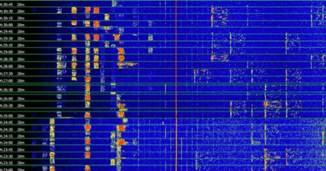
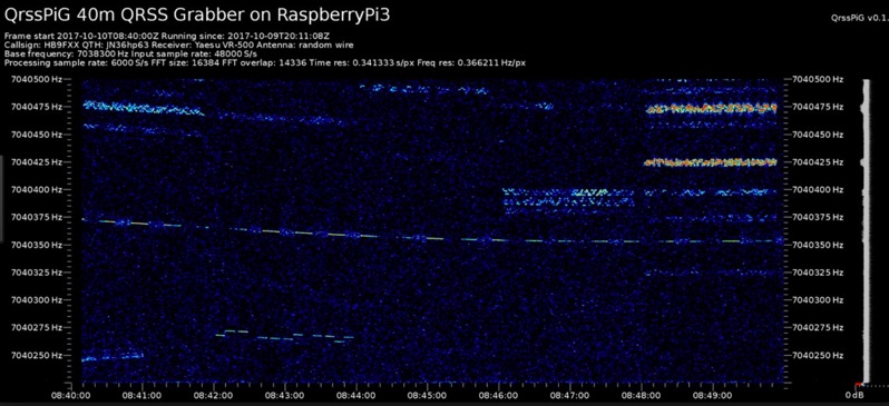 Monitoring extremely weak signals in the QRSS (Very Slow Morse) mode requires specialized receiving and processing capabilities to extract information below the typical noise floor. This project provides a software solution, _QrssPiG_, designed to run on a Raspberry Pi, enabling it to function as a dedicated QRSS grabber. It interfaces with various Software Defined Radio (SDR) devices, including the popular _rtl-sdr_ dongles and _HackRF_ units, to acquire raw I/Q data streams. The software then performs the necessary signal processing to visualize and decode these faint, long-duration CW transmissions, often operating with milliwatts of power. The system leverages the computational power of the Raspberry Pi for real-time signal analysis, allowing hams to participate in QRSS experiments and monitor distant beacons. It supports different SDR hardware, offering flexibility in setup and deployment for home stations or remote monitoring sites. The project includes detailed instructions for installation and configuration, making it accessible for those familiar with Linux environments. This grabber is particularly useful for tracking propagation on the LF and HF bands where QRSS activity is common, providing a visual representation of signal presence over extended periods.
 -
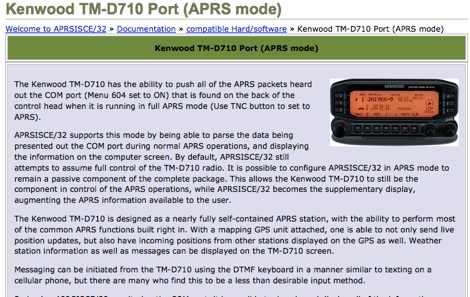 The Kenwood TM-D710 is designed as a nearly fully self-contained APRS station, with the ability to perform most of the common APRS functions built right in.
 -
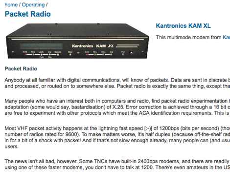 Introduction to packet radio and answers to common questions about this digital mode and about services you can use by VKFAQ
 -
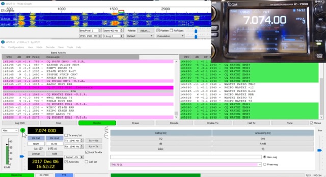 The _Icom IC-7300_ transceiver, a popular SDR rig, can be readily configured for digital modes like FT8 using _WSJT-X_ software. This guide details the necessary steps, from downloading the correct version of WSJT-X to configuring the radio's USB audio and CAT control settings. It emphasizes a straightforward approach, aiming to simplify the often complex initial setup for new digital mode operators. K0PIR shares his practical experience, outlining the specific menu settings on the IC-7300, such as USB SEND/DPT and USB MOD LEVEL, which are crucial for proper signal modulation and transmission. The resource also covers the integration of WSJT-X's built-in logging capabilities, streamlining the process of recording digital contacts without needing external logging software immediately. This setup allows for efficient operation on various HF bands. Two embedded videos further illustrate the configuration process, providing visual aids for each step, from initial software installation to making the first FT8 contact. The author's method focuses on minimizing common setup hurdles.
 -
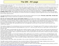
 Over 100 distinct RF connector types are available from AIR802, including popular UHF series PL-259 plugs and SO-239 sockets, designed for a wide array of coaxial cable dimensions. The company specializes in producing connectors compatible with common amateur radio cables like RG-8, RG-213, and RG-58, ensuring reliable signal integrity for antenna systems and shack interconnections. Their product line extends to various coaxial cable types and pre-made antenna cable assemblies, offering ready-to-deploy solutions for hams. AIR802 also provides custom cable assemblies and pigtails, catering to specific installation requirements for transceivers, tuners, and amplifiers. These pre-fabricated options simplify station setup, reducing the need for field termination of connectors. Michael Bryant is the contact for inquiries regarding their range of RF components, which are essential for building robust and efficient amateur radio stations.
 -
 Constructing an End-Fed Half-Wave (EFHW) antenna offers a practical solution for HF operators seeking a multiband wire antenna without the need for extensive radial systems. This design typically employs a high-impedance transformer at the feed point, matching the antenna's inherent high impedance to a 50-ohm coaxial feedline. The article specifically details a 2012 approach, focusing on a transformer with a 49:1 turns ratio, which is a common configuration for EFHW antennas. The resource outlines the construction of a wire element cut for a half-wavelength on the lowest desired band, with specific coil arrangements enabling operation on harmonically related bands such as 40m, 20m, and 10m. It discusses the physical dimensions and winding details for the matching transformer, often utilizing a ferrite toroid core to achieve the necessary impedance transformation. The content provides insights into the operational principles and practical considerations for deploying such an antenna, including methods for tuning and optimizing performance across multiple amateur radio bands. While acknowledging that the presented information from 2012 may be superseded by newer insights, it serves as a foundational reference for understanding EFHW antenna theory and construction.
 -
 The High Point Amateur Radio Club (HPARC), operating under the callsign W4UA, provides a central hub for amateur radio enthusiasts in High Point, North Carolina, and surrounding communities. The club's website outlines its long-standing traditions and civic service, which date back to the 1930s, highlighting its sustained leadership and strong membership support over decades. It serves as a resource for individuals interested in obtaining or upgrading an FCC amateur radio license, offering assistance through direct contact with club officers. The site also features a newsletter archive for meeting notices and information on club activities, including Field Day. HPARC's diverse membership shares a common interest in the amateur radio hobby, encompassing various aspects such as VHF, UHF, HF, and digital modes like D-STAR. The club's commitment to public service is evident through its involvement in ARES and Skywarn, alongside educational initiatives for new hams and those pursuing license upgrades. The site also lists repeaters and provides information on emergency communications, technical projects, and participation in events like DXCC and contests, reflecting the broad interests of its members.
 -
 The club is based in State College, Centre County, Pennsylvania, the geographic center of the Commonwealth, in the middle of the Allegheny Mountains.
 -
 Article on radio frequency interferences, with a long list of common RFI cause, like Plasma TV, Solar panels inverters, fluorescent tube lamps.
 -
 Coaxial cable stripping for PL-259 connectors requires precise measurements to ensure optimal RF performance and mechanical integrity. For RG-8X, the outer jacket is stripped 1/2 inch, the braid 5/16 inch, and the dielectric 1/8 inch, leaving the center conductor exposed. RG-58 preparation involves a 1/2 inch jacket strip, 1/4 inch braid strip, and 1/8 inch dielectric strip. These specific dimensions facilitate proper soldering and crimping, minimizing impedance discontinuities at the connector interface. Different coaxial cable types, such as RG-8 and RG-213, necessitate varied stripping lengths due to their construction. The _PL-259_ connector, a common UHF type, relies on these exact preparations for a secure fit and low-loss connection. Incorrect stripping can lead to high SWR, RF leakage, and mechanical failure, impacting overall station efficiency. The guide details these critical dimensions for several popular coax cables. Using a dedicated _coax stripper_ tool or precise measurements with a utility knife improves consistency.
 -
 The resource, "Conventional Use of Transmission Line," meticulously details the operational principles of transmission lines, emphasizing the Transverse Electromagnetic (TEM) mode of energy transfer. It clarifies that for a line to function purely as a transmission line, all currents must be confined internally, with external fields ideally zero. The discussion differentiates between balanced and unbalanced lines, asserting that while both require equal and opposite currents within the conductors, the key distinction lies in the voltage relationship of each conductor to the surrounding environment. It highlights that a good antenna pattern does not inherently confirm proper feeder balance, and that common-mode currents can lead to RF in the shack and increased noise levels, even without pattern distortion. The article further explains that a transmission line can become a radiating conductor if energy is applied in a non-TEM mode, leading to common-mode issues. It cites classic texts like Jordan and Balmain's "_Electromagnetic Waves and Radiating Systems_" and Kraus's "_Antennas_" to support its definitions of TEM mode operation. The content also explores non-transmission line applications of parallel or concentric conductors, such as _coaxial dipoles_ and _folded dipoles_, which intentionally operate in non-TEM modes for antenna functionality. The author, _W8JI_, stresses that simply measuring equal currents is insufficient to confirm a balanced feeder; phase and voltage balance to ground are equally critical.
 -
 The EA8ALP personal page, hosted on QSL.net, is currently inaccessible, presenting a 404 "Page Cannot Be Found" error. This resource was intended to feature Adelto, an amateur radio operator from the Canary Islands, likely detailing his station, operating activities, or other personal ham radio interests. The QSL.net platform, which hosts over 30,000 amateur radio websites, provides free web and email services to operators and organizations, relying on donations for support. While the specific content of EA8ALP's page is unavailable, the platform's structure suggests it would typically include information relevant to **DXing** and **contesting**, common interests for operators in geographically desirable locations like the Canary Islands. Users encountering this error are advised to contact the website owner directly or use an internet search to locate the intended content, as QSL.net cannot assist with individual site content issues.
 -
 The Greenwood Amateur Radio Society consists of a group of people who share a common interest in Amateur Radio. Our goal is to further the exchange of information and cooperation between members, to deepen our radio knowledge, improve our operating skills, and to advance the general interest and welfare of Amateur Radio in our community
 -
 Demonstrates the online presence of the West Island Amateur Radio Club (WIARC), a Canadian amateur radio organization. The resource presents fundamental club information, including contact details via an "info" email address. It also indicates the club's location within Quebec, Canada, and its focus on **ham radio** activities. The site's technical implementation notes its creation with **Arachnophilia 4.0**, a specific HTML editor. This resource, while minimal in content, serves as a digital point of contact for the WIARC. It confirms the club's existence and provides a channel for inquiries, which is typical for many local amateur radio clubs. The mention of a frame-compliant browser suggests an older web design, common for sites maintained over several years.
 -
 Extended Single SideBand is any SSB transmission that exceeds the audio bandwidth of common 2.9kHz SSB J3E modes by essb.us
 -
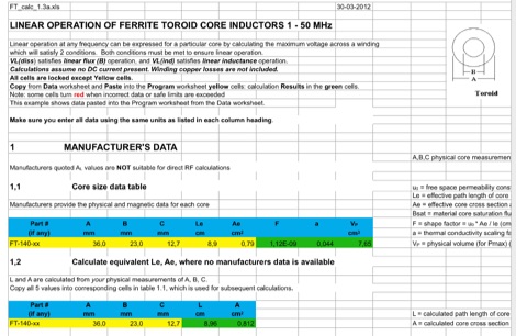 This EXCEL Program Worksheet calculates the safe operating conditons for a toroidal transformer operating between 1 and 50 MHz. Manufacturer data for complex permeability, magnetic dimensions, and saturation flux density must be available. Some core types which are commonly used in amateur transmission are included. The program produces limiting winding voltages for linear operation and temperature rise over the range of frequencies and power specified.
 -
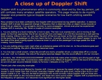 A close up of Doppler Shift, a phenomenon which is commonly observed by the lay person, yet still confuses many amateur satellite operators.
 -
 One common semiconductor material, silicon, is far more widely used in electronics than germanium, partly because it can operate at much higher temperatures. Semiconductors are crystalline materials with electrical resistivity values between conductors and insulators, whose conductivity can be altered through _doping_ with impurities like arsenic or phosphorous to create N-type (excess electrons) or P-type (electron vacancies) materials. Semiconductor devices, such as diodes, transistors, and integrated circuits, leverage these properties to control electron flow in circuits. A diode, a two-terminal device with an anode and cathode, primarily permits current flow in one direction, making it useful as a rectifier to convert AC to DC. Specialized diodes include Zener diodes for voltage regulation and Light-Emitting Diodes (LEDs) that produce light when current passes through them. Logic circuits, fundamental to digital electronics, have binary inputs and outputs, performing functions like AND, OR, and NOT gates, and can be constructed from various binary devices including solid-state diodes and transistors. A transistor is an active semiconductor device with at least three terminals (base, emitter, collector), capable of amplifying current. Integrated circuits (ICs), often called chips, are electronic circuits built on a semiconductor substrate, typically silicon. ICs are classified by transistor type (bipolar or MOS) and integration scale: Small-Scale Integration (SSI) with fewer than 10 transistors, Medium-Scale Integration (10-100), Large-Scale Integration (LSI) with 100-1,000, and Very-Large-Scale Integration (VLSI) with more than **1,000** transistors. ICs can be analog, digital, or hybrid, offering virtually limitless functions.
 -
 The Tri-pole antenna, a clever modification of a standard dipole, allows for dual-band operation by integrating a third element. This design effectively shortens the overall dipole length by 10 to 20 percent, simplifying antenna rotation and offering a compact footprint. KK4OBI's article delves into the operational principles, using a 6 and 10-meter Tri-pole as a primary example, and provides comprehensive instructions for constructing any Tri-pole antenna within the 6 to 15-meter range. Key to the Tri-pole's performance is its off-center feed, necessitating a common mode choke at the feed point for optimal tuning and reduced noise. The author outlines a methodical approach to determining element dimensions, starting with a vertical element frequency calculated as 0.47 times the sum of the desired upper and lower band frequencies. This calculation, along with K-values derived from trend lines, guides the initial lengths for the horizontal arms, demonstrating how a 10m-6m Tri-pole can achieve a total horizontal length 78% shorter than a conventional 10-meter dipole. Tuning and balancing are critical, with the article detailing adjustments to arm lengths and the vertical element to achieve balanced SWR values, as validated through 4NEC2 simulations. Radiation patterns are analyzed at various elevations, showing gains around 5.7 dBi and favorable take-off angles for DX contacts. Construction details specify aluminum tubing dimensions, U-bolts, and an SO-239 connector, emphasizing the importance of a ferrite-based choke for wideband operation.
 -

-
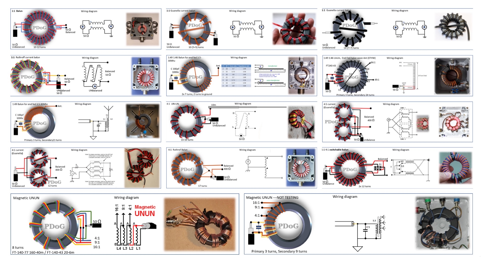 This page provides a detailed guide on the Guanella Current Balun for ham radio operators. The author shares very nice schematics, photos, and explanations on the construction and use of this type of balun. The content explains when a balun is needed and how it can help with common-mode currents in antenna systems. It also discusses the construction process, including winding the balun around a ferrite core. This resource is useful for hams looking to improve their antenna systems and reduce common-mode currents for better performance. This article is in Dutch.
 -
 The Nechako Radio Club was formed in the summer of '93 to provide a common meeting point for the local area amateur radio operators.
 -
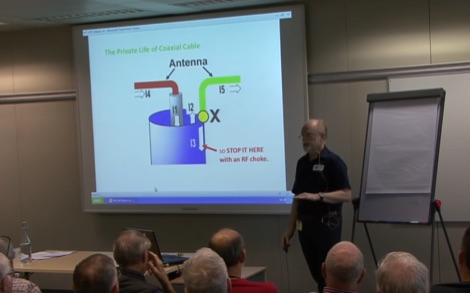 Our ideas about HF baluns have changed dramatically in recent years. The focus today is very much on suppressing unwanted common-mode RF currents, to reduce both the received noise levels and the risks of causing interference on transmit.
 -
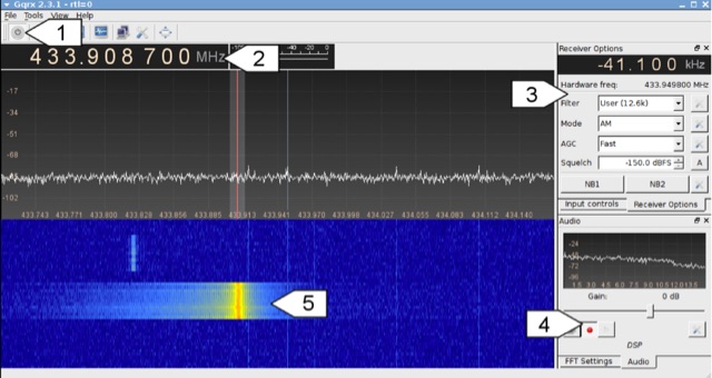 Analyzing 433 MHz radio signals from common wireless devices, such as temperature sensors and remote controls, involves understanding **On-Off Keying (OOK)** modulation. This resource details the process of capturing these signals using a Software Defined Radio (SDR) like Gqrx and then visually inspecting the captured audio data in a sound editor such as Audacity. It differentiates between **Pulse Width Modulation (PWM)** and Pulse Position Modulation (PPM) encoding schemes, illustrating how to identify and decode binary data by eye based on pulse and gap durations. The article provides a step-by-step walkthrough for decoding a wireless thermometer's data, correlating bit patterns with known temperature, humidity, and channel values. It also demonstrates decoding an RF remote control's button presses, highlighting the constant and varying parts of the transmitted packets. The content further introduces automated decoding using tools like RTL_433, explaining its capabilities in parsing various device protocols and showing how to interpret its output, including modulation type and decoded data. Specific examples include analyzing Prologue sensor protocol specifications from RTL_433's source code and noting common operating frequencies like 433.92 MHz in Europe and 915 MHz in the US.
 -
 Offers a range of high-performance RF interconnect solutions, addressing the critical need for reliable signal integrity across diverse radio frequency applications. Their product line includes custom cable assemblies, various **RF connectors** (such as SMA), adapters, and terminators, designed to meet stringent specifications from DC up to 40 GHz. These components are essential for maintaining low insertion loss and excellent VSWR in demanding environments, from test benches to operational communication systems. The company specializes in providing tailored solutions for both commercial and government sectors, emphasizing precision manufacturing in Warner Robins, Georgia. Their offerings are crucial for engineers and operators requiring specific lengths, connector types, and performance characteristics for their radio equipment and test setups. Ensuring robust connections and protection against transient voltage events, their **surge protectors** are integrated into systems to safeguard sensitive electronics from damage, a common concern in outdoor or high-power installations.
 -
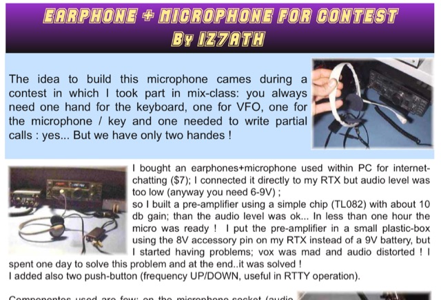 Adapting a common PC earphone with microphone to connect to a transceiver via a homemade pre-amplifier, using a simple chip with aprox 10 db gain. Includes a schematic diagram
 -
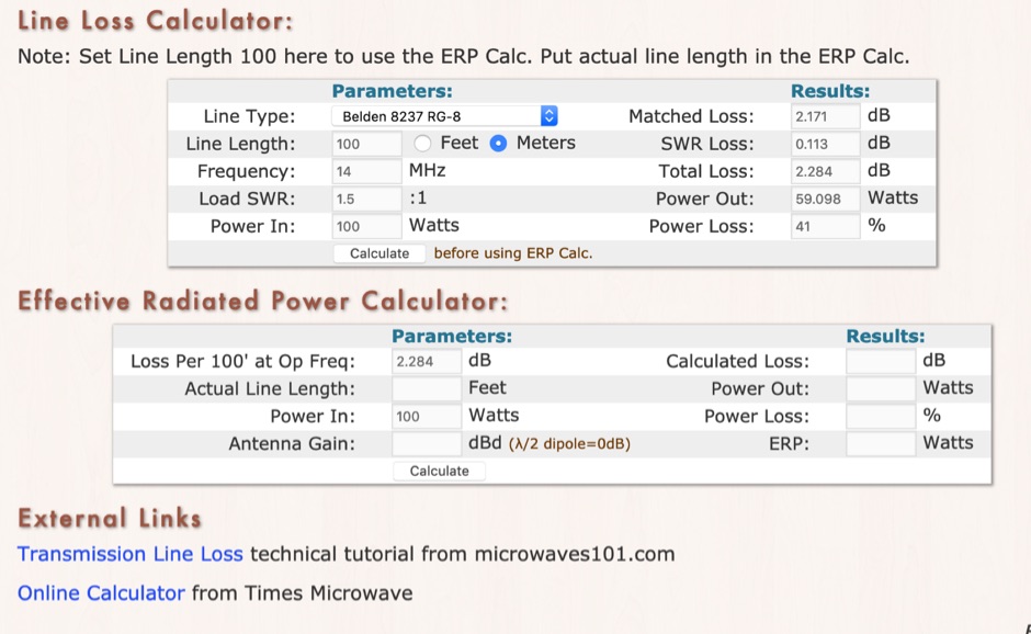 RF Feedline (Coax and Ladder-Line) Loss and ERP Calculators made with Javascript. This complex feddline loss calculator has already several line types paramenters for most common coaxial cables from Belden, Time LMR, Wireman and other common products. Result will give Matches loss, SWR loss, dB and Watts power loss.
 -
 Author experiments end fed half wave antennas using common two conductore speaker wire, this article features a couple of end-fed halfwave wires for the 40M and 20M bands.
 -
 Common mode currents are those currents that flow in the same direction on a wire bundle, as opposed to the currents that flow
 -
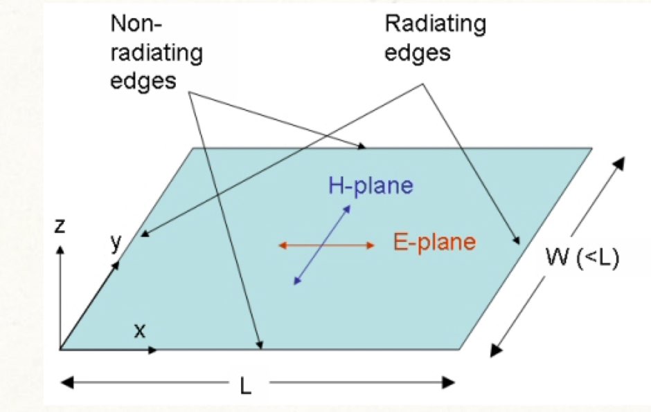 Article about the microstrip patch antennas, and in particular the rectangular, single-polarization microstrip antennas, commonly abbreviated MSA.
 -
 Article with answers to common questions as what cable types to user, cable length, how to join ends.
 -
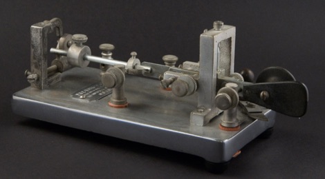 The Vibroplex Collector’s Page details the history and identification of Vibroplex semi-automatic telegraph keys, commonly known as "bugs." It traces the evolution from Horace G. Martin's 1902 Autoplex, which required a battery, to the fully mechanical Vibroplex patented in 1904. The resource explains how these keys generate automatic dots and manual dashes, helping telegraphers mitigate Repetitive Motion Disorder (RMD) and increase sending speed, thus improving their earnings. The site also covers the initial design by Alfred Vail in 1844, Jesse Bunnell's 1881 "Triumph Key," and William O. Coffe's 1904 "Mecograph." This page assists owners in identifying their Vibroplex models and determining their manufacturing dates, providing insights into the company's long history and notable figures like J. E. Albright. It notes that approximately 300,000 Vibroplexes have been produced since 1904, with the Original model still in production after more than 90 years. The resource also touches upon various Vibroplex models, including unusual, scarce, and common types, alongside legal and illegal clones from other manufacturers.
 -
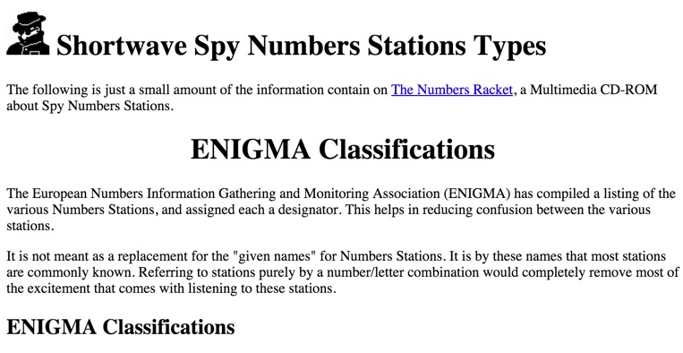 Article on common Classification of Spy Numbers stations.
 -
 The DIY 137 MHz WX SAT V-dipole antenna project details the construction of a specialized antenna for receiving weather satellite transmissions. It provides specific dimensions for the dipole elements, designed for optimal reception around the 137 MHz band, which is commonly used by NOAA and Meteor weather satellites. The resource outlines the materials required, such as aluminum tubing for elements and PVC for the support structure, along with the necessary coaxial cable and connectors. The article presents a clear, step-by-step assembly process, including how to form the V-shape and connect the feedline. It emphasizes practical considerations for mounting and weatherproofing the antenna for outdoor deployment. The design focuses on simplicity and effectiveness for amateur radio operators interested in satellite imagery. Key aspects include the precise angle of the V-dipole and the lengths of the radiating elements, which are critical for achieving the desired circular polarization response for satellite signals. The resource includes photographic documentation of the construction phases and the final mounted antenna.
 -
 The Western Washington Amateur Television Society (WWATS) is a group of amateur radio operators in the Puget Sound area with a common interest in amateur television
 -
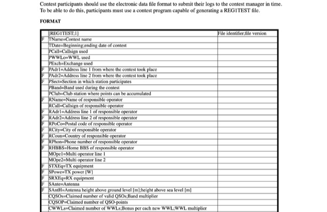 EDI is a common electronic data file format required to submit contact logs. Very popular among contest logs formats.
 -
 Clarifies the intricate process of calibrating the _Elecraft K2_ dial, addressing common user challenges and lively discussions on the Elecraft reflector. Wilhelm, W3FPR, dissects the K2's PLL synthesizer design, chosen for its low phase noise, kit-friendly duplication, and cost-effective components. The resource emphasizes the critical role of the 4000.000 kHz reference oscillator's accuracy during CAL PLL, CAL FIL, and CAL FCTR functions, noting its dependence on temperature and crystal stability for optimal performance. Explaining the K2's frequency display, the document reveals it relies on microprocessor-driven look-up tables generated by CAL PLL for VFO values and CAL FIL for BFO values. In SSB and RTTY, these combine, while CW and CWr modes also factor in the sidetone pitch. The author details inherent limitations, such as the 10 Hz increment resolution of the dial and varying PLL step sizes—from 3 Hz on 160 meters to 10 Hz on 10 meters. BFO increments range from 20 to 35 Hz, collectively limiting practical dial accuracy to within **20 Hz** with diligent effort, or **30 Hz** for a slightly less demanding task. The guide outlines a four-step calibration procedure: setting the reference oscillator, running CAL PLL, running CAL FIL, and setting all BFOs. It highlights the _N6KR Method_ as a particularly easy and accurate approach, requiring only the K2 and a known frequency source like WWV for zero-beating, eliminating the need for external test equipment.
 -
 Enables Android users to operate various _miniVNA_ antenna analyzers via Bluetooth, USB, or Wi-Fi, providing a portable solution for RF measurements. The application supports full control over data acquisition, offering features like custom frequency range selection from 1 KHz to the VNA's full range, and automatic screen adaptation for diverse Android device resolutions. It facilitates intuitive, wizard-based calibration for both reflection and transmission modes, saving calibration data for different VNA types (Standard, Pro, Pro with Extender) to avoid repeated procedures. The software displays critical parameters such as SWR, |Z|, Return Loss, Phase, Rs, and |Xs| on 2-axis graphs or Smith charts, with multi-touch gestures for zoom and frequency shift. It includes a frequency generator mode with independent channels and attenuator control for the miniVNA Pro, along with a sweeper function. The cable data mode automatically calculates phase and loss, measures cable length from less than 1 meter to hundreds of meters, and includes a table of common coax cable velocity factors. An experimental X-tal mode measures resonance frequency, Rs, and Q. Data export options include CSV, ZPLOT, and S1P formats, with CSV import capability. The application also features an SM6ENG Audio mode for SWR tuning without visual reference and provides a miniVNA battery voltage indicator. It supports a wide frequency range, with the miniVNA Extender extending coverage up to **1500 MHz**. The application is compatible with Android version 2.2 and later, tested on devices like the _Galaxy TAB 7.7 P6800_.
 -
 256 memories enable the _AT-AUTO_ to recall settings across multiple bands, making it efficient for operators who frequently change frequencies. The tuner is compatible with various antennas and amplifiers, such as the Mercury LUX, and integrates seamlessly with radios like the FLEX 6400 using an RS232-USB connection. This integration allows the tuner to follow frequency changes without additional input, enhancing operational efficiency. Despite being out of production, the _AT-AUTO_ remains supported by Kessler Engineering, which offers firmware updates and repair services. The tuner features a cross-needle SWR meter, providing quick visual feedback during tuning. It also includes a QRO keyline circuit to protect amplifiers during tuning. Users appreciate the tuner's ability to track radios via CAT control, avoiding automatic tuning during QSOs, a common issue with other models. The _AT-AUTO_ is praised for its durability and performance, with many users noting its reliability over years of use. Its ability to handle legal limit power and its balanced line output make it a versatile choice for serious operators. Although it lacks some features like multiple coax outputs found in other models, its robust build and continued support make it a valuable tool for HF enthusiasts.
 -
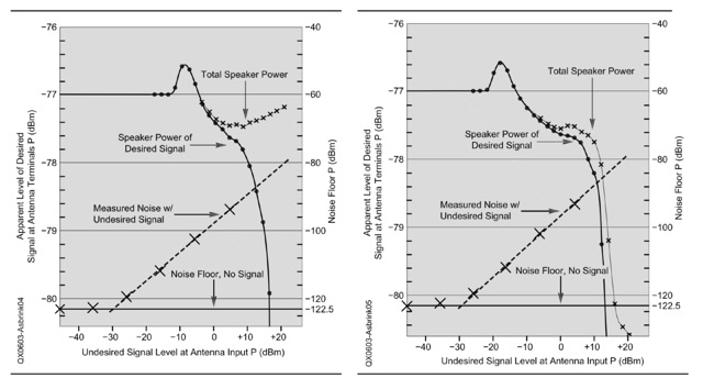 An explanation of the different procedures and definitions that are commonly used for blocking dynamic range (BDR) measurements. Dynamic range in general is the ratio between the weakest signal a system can handle and the strongest signal the same system can handle simultaneously without an operator switching attenuators or turning volume potentiometers
 -
 Mitigating impulse-type noise, a common challenge in the **HF radio spectrum**, often requires specialized processing before the signal reaches the transceiver's receiver stages. The NR-1 addresses this by functioning as an RF interference removal device, specifically a noise blanker, targeting transient noise sources. Its operational range extends from 1.6 MHz to beyond 70 MHz, making it suitable for various amateur radio bands and general shortwave listening applications. Unlike QRM eliminators or X-phasers, the NR-1 does not require a separate noise antenna for its operation, simplifying its integration into existing station setups. The device's design focuses on wideband performance, allowing its use both within and outside the allocated amateur radio frequencies. Documentation detailing its operation is available, providing insights into its technical specifications and deployment. This unit is a hardware product, conceptualized and implemented by SV3ORA.
 -
 Determining the characteristic impedance (Z) of an unknown coaxial cable, a common challenge for many radio amateurs, can be resolved with a straightforward method. The impedance of a coaxial cable is derived from its inductance and capacitance, and importantly, these values are independent of the cable's length or the operating frequency. This means that measuring a random length of cable, such as 20 meters, provides sufficient data for calculation. The core of this technique involves an LC-meter to obtain the inductance (L) in microHenries (uH) and capacitance (C) in microFarads (uF). The impedance is then calculated using the formula Z = L/C. For instance, a measurement yielding L=1.2uH and C=450pF (0.00045 uF) results in an impedance of 51.6 Ohms, closely matching **RG-58** specifications. Similarly, a TV coaxial cable with L=1.8uH and C=320pF (0.00032 uF) calculates to 75 Ohms. While the accuracy of this method, depending on the LC-meter's tolerance, is approximately 10%, it proves sufficiently precise for practical determination of unknown coaxial cable impedance, as noted by Makis, SV1BSX, who credits Cliff, K7RR, for the formula's dissemination.
 -
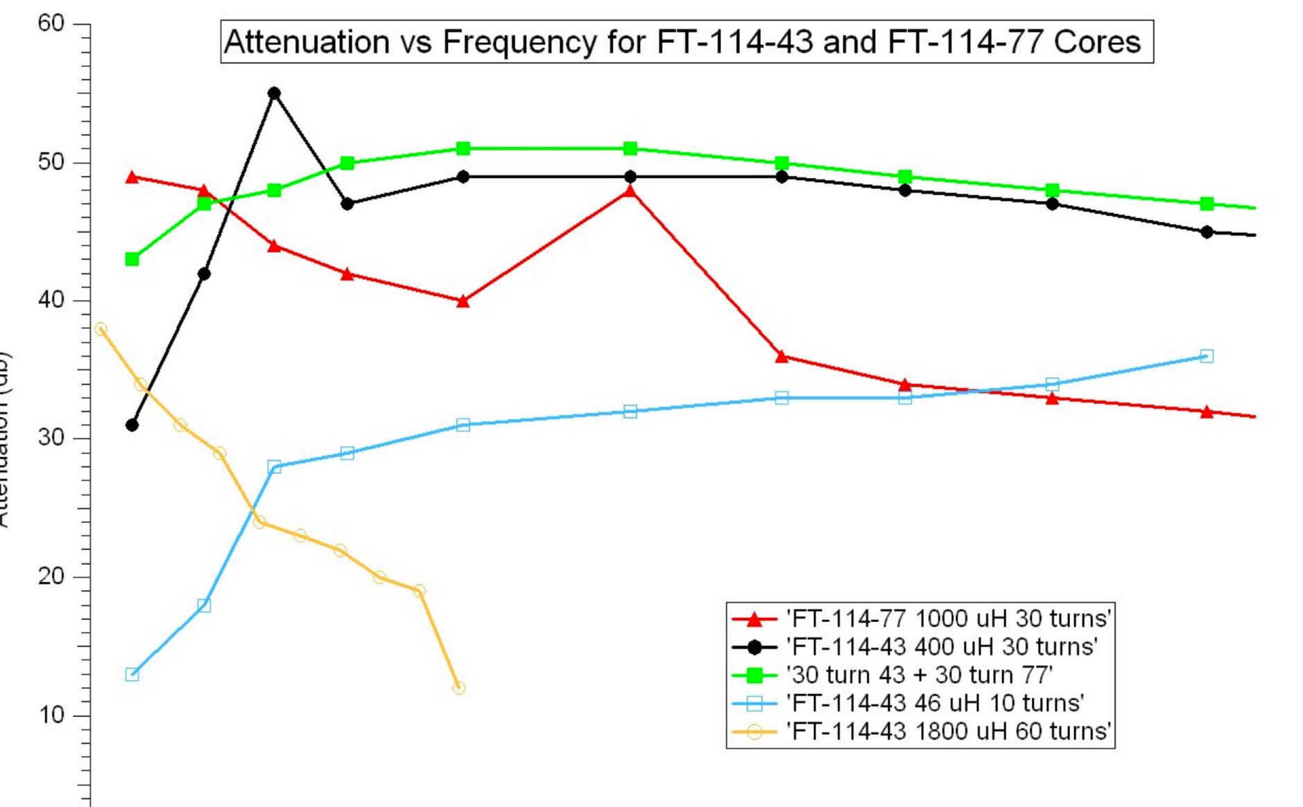
 The Linked Dipole is a multiband antenna designed for 80/60/40/30/20m bands, optimized for the (tr)uSDX low bands configuration. It incorporates a 1:1 Balun to prevent common mode currents, ensuring balanced operation with coaxial cable. The Balun, wound on an FT140-43 core, achieves 37-40dB attenuation. The design includes a 3D-printable housing for compactness and waterproofing, with labeled link insulators for ease of use. Wire lengths were meticulously adjusted for optimal performance with a 7m pole and 3m rope extension, ensuring the antenna's ends are off the ground for improved behavior. The project includes downloadable printables for DIY construction.
 -
 Building A Full-Wave Quad Loop Antenna for 6 Meters. This is an easy antenna to build and the materials cost about $15-20. It exhibits 1.8dB gain over a 1/2-wave dipole. Using an open-wire parallel feedline (commonly called ladder line) with an antenna tuner, it tunes up on the 10m band as a 5/8-wave loop as well
 -
 Constructing a dual-band antenna for 40 and 20 meters often involves compromises in size or complexity. This resource presents a compact _open sleeve dipole_ design that addresses these challenges by using 450-ohm ladder line and folded elements to achieve a total length of approximately **17.17 meters**, significantly shorter than a full-size 40-meter dipole. The design leverages electromagnetic coupling, where a primary radiator handles the 40-meter band, and a second conductor resonates on 20 meters without direct electrical connection. This configuration eliminates the need for traditional traps, loading coils, or switching components, simplifying construction and reducing potential loss points. The antenna is fed with RG-58C/U coaxial cable, and a common-mode choke is recommended at the feed point to suppress sheath currents, ensuring a cleaner radiation pattern and minimizing RF in the shack. The design is well-suited for portable operations, field deployments, temporary installations, and restricted urban environments where space is a premium, offering solid performance on both HF bands.
 -
 PRO-LINK specializes in the manufacturing and distribution of high-quality cabling solutions, including a wide array of fiber optic cables and various coaxial cable types. Their product line encompasses 50-ohm and 75-ohm coaxial cables, essential for diverse RF applications, alongside specialized RF cables and 10Base-T networking cables. The company also provides a selection of connectors and custom cable harnesses, catering to specific installation requirements. Since 1988, PRO-LINK has offered a 5-year warranty on its products, underscoring a commitment to durability and performance. The product catalog details specifications for different cable constructions, such as _RG-58_, _RG-213_, and _LMR-400_ equivalents, which are commonly used in amateur radio installations for antenna feedlines and inter-component connections. Their offerings support both commercial and amateur radio operators seeking reliable signal transmission. The company's focus on robust cable and connector solutions addresses the critical need for low-loss transmission lines in radio communication systems, ensuring signal integrity across various frequency bands.
 -
 A 60-foot available space, for example, might necessitate a shortened multiband dipole array to cover 80, 40, and 15 meters effectively. This resource details the construction of such an antenna, combining full-size and coil-loaded dipoles on a single feedline. It addresses the common challenge of fitting multiple HF bands into restricted physical footprints, providing practical guidance for hams with smaller backyards or portable operations. The core of the offering is an interactive calculator that determines required loading coil inductance and dipole lengths for various amateur bands from 160m to 10m. Users input their available space, and the tool provides dimensions, coil turns, and an efficiency rating (Good or Fair) based on the antenna's electrical length relative to a quarter-wavelength. It also suggests suitable _PVC_ pipe diameters for coil forms. The article further illustrates a center feed-point assembly using an 18-inch section of 2-inch _PVC_ pipe, detailing eye-bolt spacing and coaxial connector installation. It emphasizes the importance of adequate spacing between parallel dipoles and offers customization options for the feed-point, including the addition of a _Balun_ for improved feedline isolation.
 -
 This article discusses how volume reduction can help in the reception of weak signals by reducing the noise level. It is commonly known that reducing the volume also reduces the background noise, and especially in the reception of weak digital signals it can be beneficial