Search results
Query: matching
Links: 205 | Categories: 3
-
 This comprehensive article dispels common misconceptions about Standing Wave Ratio (SWR) in amateur radio. The author explains that SWR is not an antenna property but a measure of the entire antenna system, representing the mismatch between transmission line and load impedance. Contrary to popular belief, modest SWR values (under 3:1) typically cause minimal power loss in HF applications. The article demonstrates mathematically why obsession with achieving 1:1 SWR is often unnecessary, explains when SWR matters more (QRO, QRP, VHF/UHF), and explores effective matching techniques including proper ATU placement and quarter-wavelength transformers.
 -
 VE1ZAC's analysis details the performance of **MFJ927** and **SGC239** autotuners with portable HF vertical antennas, specifically comparing 31 ft and 43 ft configurations. The resource originated from challenges encountered during a Maritime QSO Party roving operation, necessitating a lightweight and easily deployable antenna system. Target bands for the contest included 80, 40, 20, 15, and 10 meters, with a maximum power handling of 100 W CW. The author utilized a 30-foot carbon fiber push-up pole to support a vertical wire element, noting its 2 lb weight and reliability. EZNEC modeling was employed to predict performance, showing favorable results for a 30-foot vertical with elevated radials, particularly on 40 and 20 meters. Feedpoint impedance measurements, taken with an AIM4170C, are presented for various HF bands, both with and without a 41-foot RG6 stub designed to reduce reactance on 80 and 20 meters. The stub significantly improved matching on these bands, easing the tuner's workload. Operational tests revealed issues with the MFJ927's reliability during contest setup, leading to reliance on the K3's internal tuner. The SGC239, tested post-contest, performed flawlessly. A detailed side-by-side comparison covers mechanical aspects, connection options, power bias, impedance range, board quality, and documentation. Modifications to the MFJ927, including a new aluminum case, white paint for heat reduction, and upgraded impedance-measuring resistors, are also described.
 -
 145 MHz is the target frequency for this 2-meter Skeleton Slot Yagi Stack antenna project. The design focuses on feeding two stacked Yagi antennas using a skeleton slot radiator, which is a unique approach for VHF enthusiasts. The project details the construction process, including the loop tapered matching section for impedance matching, ensuring optimal performance. The use of specific components like the EH789 element holder and MB456 main mast bracket is highlighted, providing clarity on the assembly process. The construction utilizes 20x20 box aluminum bar for durability and precision. Key dimensions, such as the element length (ER-ED4) and main boom spacing (MM123), are meticulously outlined. This attention to detail aids in replicating the antenna design accurately. The downloadable PDF offers comprehensive instructions, making it accessible for amateur radio operators interested in VHF antenna construction. This project is particularly beneficial for those looking to optimize their 2-meter band operations. The inclusion of a skeleton slot radiator and loop tapered matching section demonstrates advanced techniques in antenna design, catering to both intermediate and advanced builders.
 -
 An Arduino-based interface provides a remote tuner call command for Icom **IC7700** and **IC7800** transceivers, addressing the lack of a built-in function for external tuners such as the MFJ 998RT. This setup initiates a low-power transmit signal, typically 15 watts, allowing the remote autotuner to perform its matching sequence. The article details the required CI-V line communication and modifications to existing Arduino code, specifically referencing contributions from Jean-Jacques ON7EQ for improved Icom interrogation routines. The system involves a sequence of steps: storing the transceiver's current mode and power, disabling the internal autotuner, activating a control relay to interrupt the amplifier line, switching to RTTY mode at low power, and initiating transmit. The transmit duration is manually controlled by the operator, observing the SWR meter until a low SWR is achieved, then a second button press stops the transmission. A built-in 4-second transmit limit provides a safety measure. After tuning, the routine restores the original mode and power settings, re-enables the internal autotuner, and performs a brief 2-second RTTY transmission for internal tuner adjustment. The circuit diagram includes a Panasonic form 2 relay for amp control and emphasizes critical delays in the Arduino code for stable operation at 9600 baud CI-V communication. Compatibility with logging software like DXLab, N1MM, and N3FJP is noted, with specific interrogation time settings required to avoid conflicts.
 -
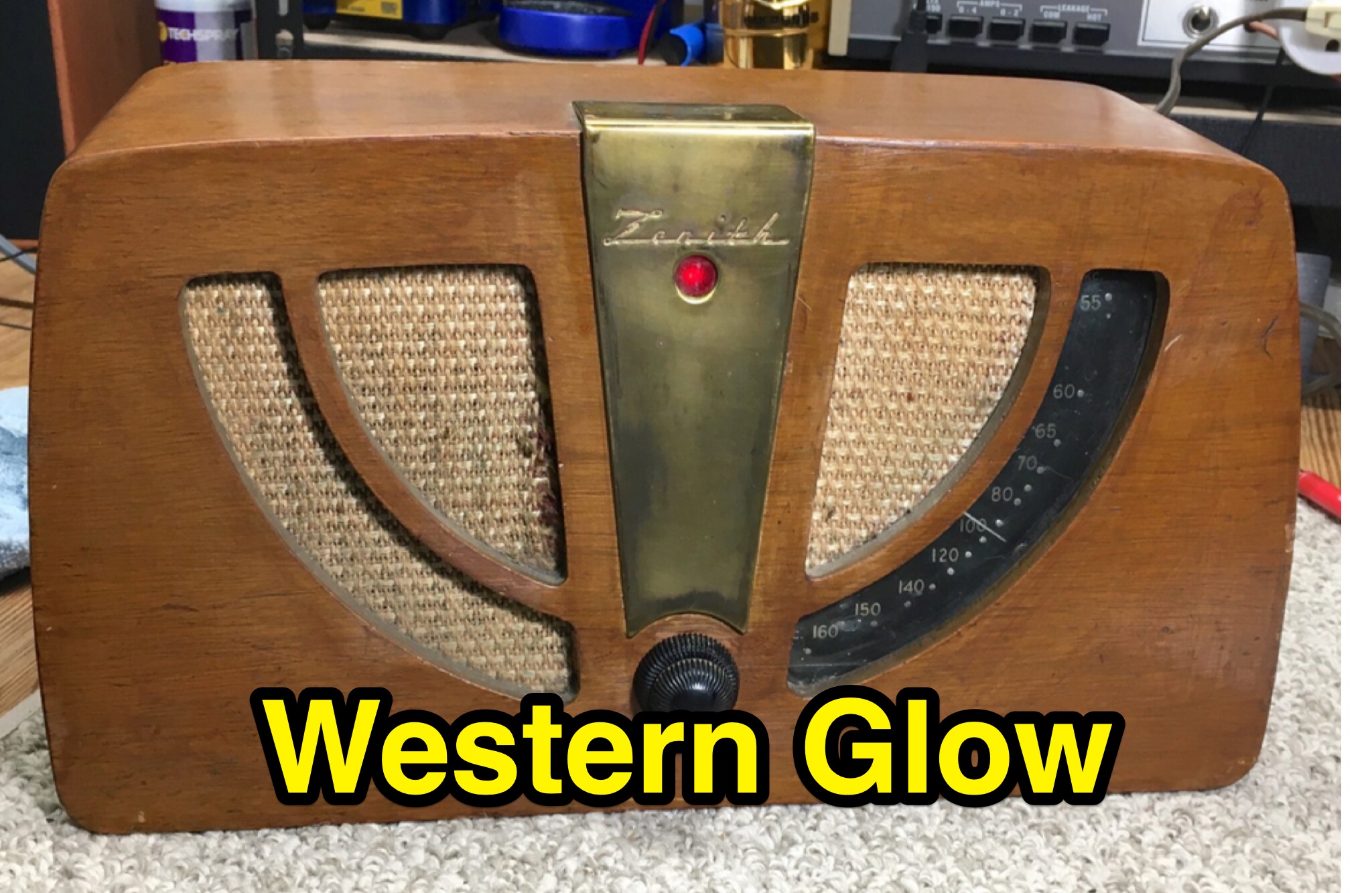 Service devoted to vacuum tube testing for HIFI, guitar, and vintage radio applications. Western Glow Tube Service offer a vintage radio repair service, they consider radio services more as a kind of tune-up, not a tradional repair service or restoration, although Level 3 is a nearly full restoration. Our services are geared toward radios that are mostly functional and not missing any significant parts except tubes.