Search results
Query: 40 antenn
Links: 558 | Categories: 11
Categories
- Antennas > 40M > 40 meter Dipole Antennas
- Antennas > 40M > 40 meter Loop Antennas
- Antennas > 40M > 40 meter Magnetic Loop Antennas
- Antennas > 40M > 40 meter Vertical Antennas
- Antennas > 40M > 40 meter Delta Loop Antennas
- Antennas > 40M > 40 meter Yagi Antennas
- Antennas > 40M
- Radio Equipment > HF Vertical Antenna > Butternut HF2V
- Radio Equipment > HF Vertical Antenna > Cushcraft R8
- Antennas > Morgain
- Antennas > Vertical
-
 Constructing a portable, high-gain antenna for _AO-40_ satellite operations presents unique challenges, particularly regarding mechanical stability and parabolic accuracy. This resource details the build of a 1.2-meter "brolly dish" antenna, utilizing a non-conducting fiberglass umbrella frame as its foundation. The project outlines a method for achieving a parabolic shape using stressed aluminum fly screen mesh, guided by practical geometry and a temporary dowel template. Key steps include selecting an appropriate umbrella with a suitable f/D ratio (ideally >0.25), removing the original fabric, and precisely cutting and attaching eight segments of fly screen to the struts to form the reflective surface. The construction process, which took approximately five hours for the author, _G6LVB_, resulted in a dish with an f/D of 0.27 (depth=270mm, diameter=1160mm, f=310mm). The article also describes a modification to a _TransSystem AIDC_ feed, incorporating a PCB reflector behind the dipole for easier mounting. Performance tests at a squint angle of 15 deg and a range of 50,000km yielded a signal-to-noise ratio of 33dB on the S2 beacon and 23dB for SSB signals, indicating strong reception. The author notes that the modified umbrella may not close fully without risking surface disfigurement.
 -
 A Half wave antenna has a high impedance feed point. This can be matched using a 1/4 wave stub matching section and converts the 40m vertical into an L-shaped 20m J-Pole antenna. The 300 ohm feeder used for this purpose must be kept away from the ground.
 -
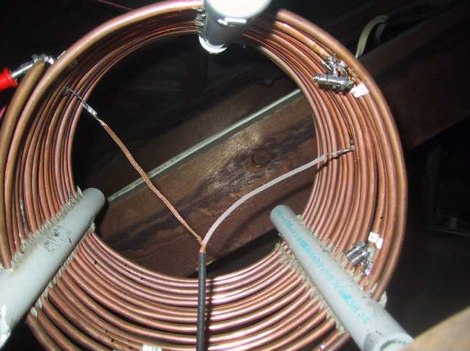
 Compact and efficient magnetic loop antenna that cover from 40 to 10 meters project by G8ODE published by RSARS
 -

-
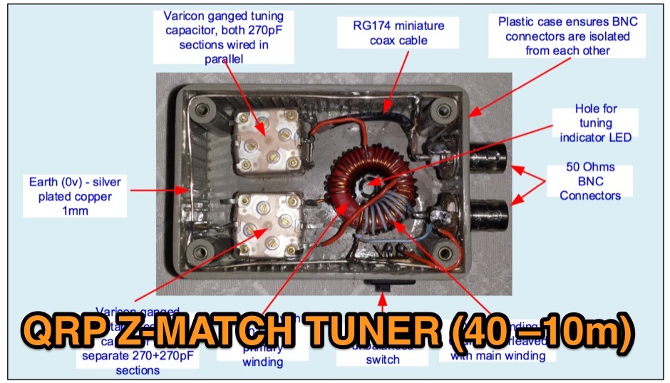 The Z Match is really a basic L Match consisting of a series capcitor and variable shunt inductor, coupled to the antenna using the RF transformer action.
 -
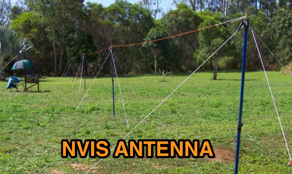 How to homebrew a ENVIS antenna for 80 and 40 meters band
 -
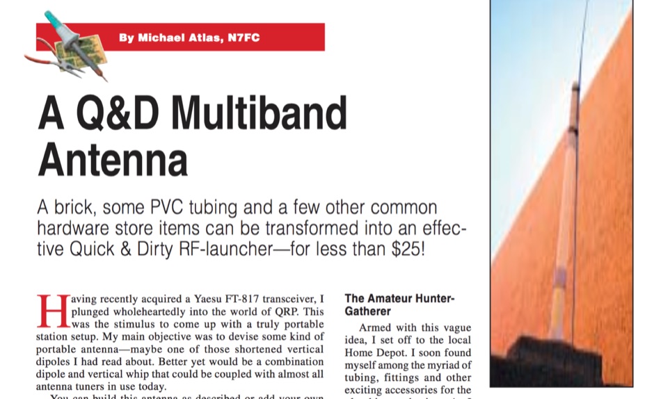 A brick, some PVC tubing and a few other common hardware store items can be transformed into an effective Quick and Dirty RF-launcher for less than $25! By Michael Atlas, N7FC
 -
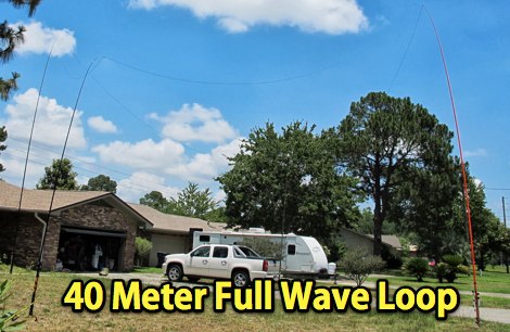 A 7MHz Full wave loop antenna in diamond shape for field day operations made with three 31 foot Jackite poles
 -
 Presents the design and performance of a 4-element wire Yagi antenna for the 40-meter band, building upon VE3VN's earlier 3-element switchable wire Yagi. The resource details the antenna's evolution, highlighting the transition from a 3-element to a 4-element configuration and the resulting improvements in gain and front-to-back ratio. It provides specific insights into the antenna's construction and expected operational characteristics. VE3VN shares insights from field results, noting the antenna's performance on 40 meters. The discussion includes the antenna's pattern and matching characteristics, crucial for any DXer or contester looking to optimize their signal on this popular HF band. The author's experience with the previous 3-element design informs the enhancements made to this 4-element iteration. The article includes a visual representation of the antenna's current view, offering a practical perspective on its physical layout. It serves as a valuable reference for hams considering a directional wire antenna for 7 MHz operations, demonstrating a practical approach to achieving enhanced directivity and gain.
 -
 The ZS6BKW antenna, a popular multiband wire antenna, offers improved band matching compared to the traditional G5RV. This construction guide details the process, beginning with specific dimensions: 13.11 meters (43 feet) for the 450-ohm ladder line and initial dipole arm lengths of approximately 14.8 meters each. It emphasizes the critical role of an _antenna analyzer_ for accurate tuning, particularly for determining the velocity factor of the ladder line and achieving a 1:1 impedance match. The article outlines the materials required, including a 1:1 current balun, 450-ohm window line, wire for the dipole arms, and a 50-ohm non-inductive resistor for testing. It provides a step-by-step procedure for cutting the ladder line to its electrical half-wavelength, explaining how to calculate the velocity factor using measured and free-space frequencies. For instance, a measured 50-ohm impedance at 12.54 MHz with a calculated free-space half-wavelength frequency of 11.44 MHz yields a velocity factor of 0.91. Final adjustments involve hoisting the antenna to its operational height and fine-tuning the dipole arm lengths to achieve optimal SWR, specifically targeting 14.200 MHz. The _ZS6BKW_ design is noted for its performance on 80m, 40m, 20m, 10m, and 6m, though it is not optimized for 15m operation. The author, _VK4MDX_, shares practical tips for durable construction using stainless steel wire and cable clamps.
 -
 The **HFRadioSales.au** resource provides a commercial outlet for amateur and commercial radio operators seeking HF SSB equipment and related services. It focuses on the Australian market, offering new and refurbished transceivers, antennas, tuners, and a wide array of spare parts for brands like Codan, Barrett, and Qmac. The site details its role as a licensed dealer for new Barrett Communications and Codan radio and antenna systems, including specific models such as the Barrett 4050, 2050, and 950, and Codan Envoy and NGT series. This platform supports various applications, including vehicle, 4WD, outback, marine, and base station setups, catering to networks like HF Radio Club, VKS737, and RFDS. It also features commercial-grade antennas from Bushcomm, such as the BBA100C and SWC100, available for fast shipping from their Queensland warehouse. The site includes an FAQ section with general information on mobile HF communications in Australia and timelines for specific transceiver models.
 -

-
 Demonstrates the design and construction of a compact, portable multi-band mini-delta loop antenna, specifically optimized for /P (portable) operations from remote locations like Scottish islands. The resource covers the theoretical underpinnings of half-wave loops, contrasting closed and open configurations, and then details the application of a folded dipole principle to achieve a 50-ohm match for direct coax feed. It presents empirical formulas for calculating element lengths, considering the velocity factor of common wire types, and provides a detailed example for a 20m (14.175 MHz) version. The article includes a comprehensive table of dimensions and allowances for a five-band (20m, 17m, 15m, 12m, 10m) mini-delta beam, along with construction hints for the central support and balun. It specifies a 1:1 trifilar balun wound on a ferrite rod and describes the antenna adjustment process using an _MFJ-259B Antenna Analyser_. Initial test results indicate an SWR of 1:1 at resonance and a bandwidth of approximately 240 kHz on 20m, even at a low height of five feet above ground. The distinctive utility lies in its focus on a practical, easily deployable beam antenna for portable DXing, offering a viable alternative to more complex or larger arrays.
 -
 The Vee Beam antenna project presents a versatile solution for hams, enabling operation across all eight High Frequency bands (80m to 10m) with significant gain on 20m to 10m. This easy-to-construct antenna utilizes two long wires at an angle, enhancing directional performance and minimizing ground losses. With a low visual profile, it is discreet and effective for various applications. The design allows for optimal leg lengths and included angles, ensuring robust performance while maintaining simplicity in construction and operation. The V Beam antenna is an aerial that you can use on all eight High Frequency amateur bands (80, 40, 30, 20, 17, 15, 12 and 10m) with an antenna tuner, and which gives significant gain on the five bands from 20 to 10 meters band.
 -
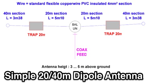 A simple TRAP-dipole project for 20 and 40m bands includes EZNec simulations
 -
 Design plan of an array of a two element yagis for 80m and a 3 element 40m antenna sharing a single 12 meters long boom by EA5DY
 -
 A 500-watt mobile antenna project details the conversion of an old 10m hamstick into a highly efficient, multiband "bugstick" for HF operation. The core modification involves replacing the original coil with 25 turns of 6 turns-per-inch, 1.5-inch diameter coil stock, fabricated from #14 wire. This design, intended for a 3-magnet mount on a vehicle cab, achieves resonance on multiple bands by shorting out specific turns on the coil, similar to a **bugcatcher** antenna. Measurements taken with an MFJ-259 analyzer on a GMC pickup show 0 turns shorted for 20 meters (14.2 MHz), 10 turns for 17 meters, 16 turns for 15 meters, 19 turns for 12 meters, and 23 turns for 10 meters. The construction emphasizes using UV-resistant tie-wraps and #14 solid wire with crimp lugs for robust RF connections, bypassing the fiberglass rod for current flow. A bonus section details a 40-meter version, utilizing 48 turns of 8 TPI, 2-inch diameter coil stock.
 -
 Near Vertical Incidence Skywave (NVIS) and the 40 meter Novice Sub-band.
 -
 Calculate EH Antenna, 20m 40 80m. Fotos, Original eh antenna building.
 -
 A schematic antenna for a 40-80 Morgain dipole antenna with diagram and pictures, article partially in german
 -
 A lightweight inverted vee antenna that can be supported by a 10 metre long fiberglass squid pole. The antenna is designed to cover 10, 15, 20, 40 and 80 m bands.
 -
 An Off-center-feed antenna that covers 80, 40, 20, 17, 15, 12, 10, and 6 meters
 -
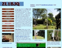 A magnetic loop antenna for 7 Mhz by ZL1BJQ
 -
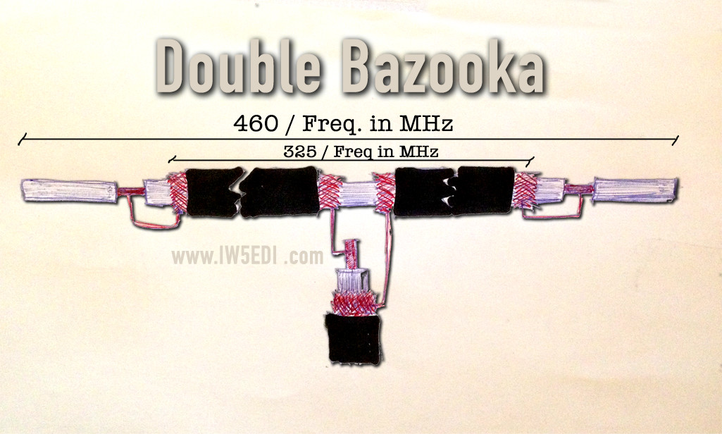 Double Bazooka Antenna, a simple coax based and broad band antenna you can easily build
 -
 Inverted Vee antenna for 40m with simulation data by DF9CY
 -
 This 4m Slim Jim Antenna is cheap and easy to build yet it greatly out performs the more usual dipole due to its low angle of radiation. An SWR of 1:1 is obtainable across the 4m ham radio FM band with a simple adjustment.
 -

-

-
 Building an omnidirectionnal antenna for the 23 cm band, 1240 - 1270 Mhz
 -
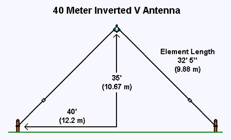 This 40 meter Inverted V antenna was tested and tuned at a height of 35 feet and proved excellent results. The ends of the antenna are about 11 feet above the ground. Article and video available
 -
 DF9CY experience on a vertical antenna for 40 meter band
 -
 A short dipole wire antenna for 40 meters band. It is a folded dipole that do not make use of coils and can be used either in horizontal or inverted V configuration
 -
 An attic antenna for 40 and 80 meters band by NS1W
 -
 A homemade VHF/UHF vertical antenna made essentially with RG58 coax cable, with a 9 turns choke balun to prevent the shield acting as a RF Radiator.
 -
 If you have space constraint at your QTH for a HF antenna, you can try contructing this HF magnetic loop antenna for 40-20 meters bands
 -
 A trapped dipole antenna based on the orignal W3DZZ antenna design resonating on 80 40 20 15 10 meters
 -
 Shortened vertical antenna for 40 meters band an homebrew project
 -
 A bowtie antenna is a type of antenna that reputedly provides higher gain at lower radiation angles than a center-fed dipole antenna at heights considerably less than 1/2 wavelength above ground.
 -
 A 50-ohm 10W resistor forms the core of this portable QRP antenna, designed by _K0EMT_ for convenient operation on 160m and 80m. The construction involves soldering the resistor to a BNC connector, with one lead to ground and the other to the center conductor, then insulating the assembly. This minimalist design aims to provide a highly portable solution for low-band QRP operations, acknowledging the inherent trade-offs between antenna size and efficiency. Testing with an antenna analyzer revealed low SWR on both 160m and 80m, with a Yaesu FT-817 confirming good matching. While 40m and 30m showed higher SWR, the primary focus remains on the lower bands. The author successfully tested the antenna with **2.5W CW** output, demonstrating its practical application for QRP field operations where ease of deployment is paramount, even if it means sacrificing some **gain** compared to full-sized antennas.
 -
-
 An homemade portable trapped dipole antenna for 40 and 80 meters band with an optional extension for the 20 meters.
 -
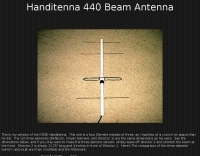 A 4 elements handitenna for 70 cm band. This is my version of the K5OE Handitenna. This one is a four Element instead of three, as I had less of a crunch on space than he did. The 1st three elements (Reflector, Driven Element, and Director 1) are the same dimensions as his were.
 -
 This article describes a simple Inverted L antenna for the HF bands designed to work on 80m, 40m, 30m and 20m
 -
 Extension to an existing fan dipole originally modeled for 40 20 and 6 meters. This modification will add 80 15 and 10 meter bands.
 -
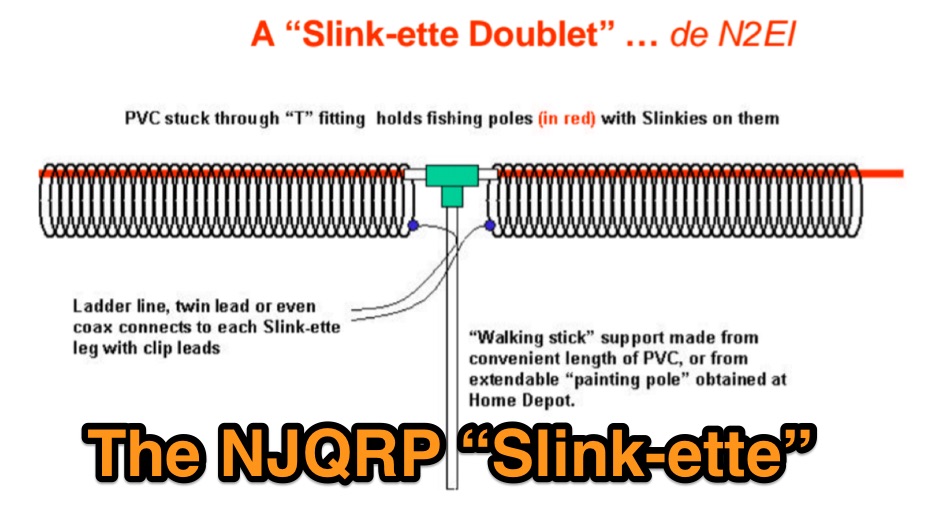 A Slinky-based doublet or loaded vertical QRP antenna tested for 40 meters band
 -
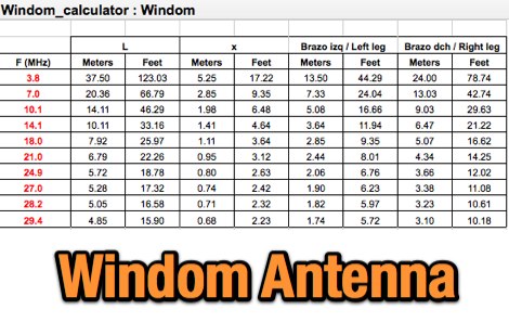 This article describes the characteristics of the Windom antenna and shows the results of several simulations made with MMANA-GAL, covering models optimized for the 20 m, 40 m and 80 m bands.
 -
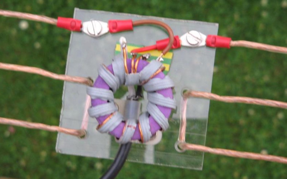
 DF9CY implementation of W1HIS suggestion of inserting a common mode choke into a 40m antennas feed-line.
 -
 An inverted triangle Delta Loop Antenna for the 40 meter band made with aluminium pipes, each element is 14,2 meters including a home made aluminium mount.
 -
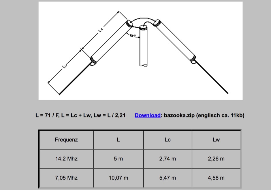 A bazooka antenna design in German with dimensions for 20m and 40m band with RG174 coax cable stronger than the common RG58
 -