Search results
Query: trans
Links: 399 | Categories: 136
This query is too generic. Please try adding an additional term to focus your research.
Categories
- Radio Equipment > HF Transceivers
- Technical Reference > QRP Projects > QRP CW Transceiver
- Manufacturers > Transceivers
- Manufacturers > Transverters
- Technical Reference > Transverters
- Radio Equipment > HF Portable Antenna > TransWorld Antennas TW2010
- DX Resources > Beacons > 10 GHz Beacons
- Antennas > 160M
- Software > ACARS
- Shopping and Services > Amateur Television
- Manufacturers > Antenna Tuners
- Shopping and Services > Regional > Asia
- Internet and Radio > Auctions
- Software > Audio Recorders
- Manufacturers > Broadcasting Equipment
- Shopping and Services > Regional > Canada
- Manufacturers > Transceivers > CB Radio
- Technical Reference > Programming Radio > Cheat Sheets
- Operating Modes > Radio Direction Finding > Clubs
- Technical Reference > Components
- Software > D-STAR
- Software > Digital Amateur Television
- Operating Modes > Satellites > Digital Satellites
- Manufacturers > Antennas > VHF UHF Microwave > Discone Antennas
- Radio Equipment > HF Transceivers > Drake TR7
- Software > DRM
- Technical Reference > Dummy Loads
- Software > DX Cluster
- Radio Equipment > HF Transceivers > Elecraft K2
- Radio Equipment > HF Transceivers > Elecraft K3
-
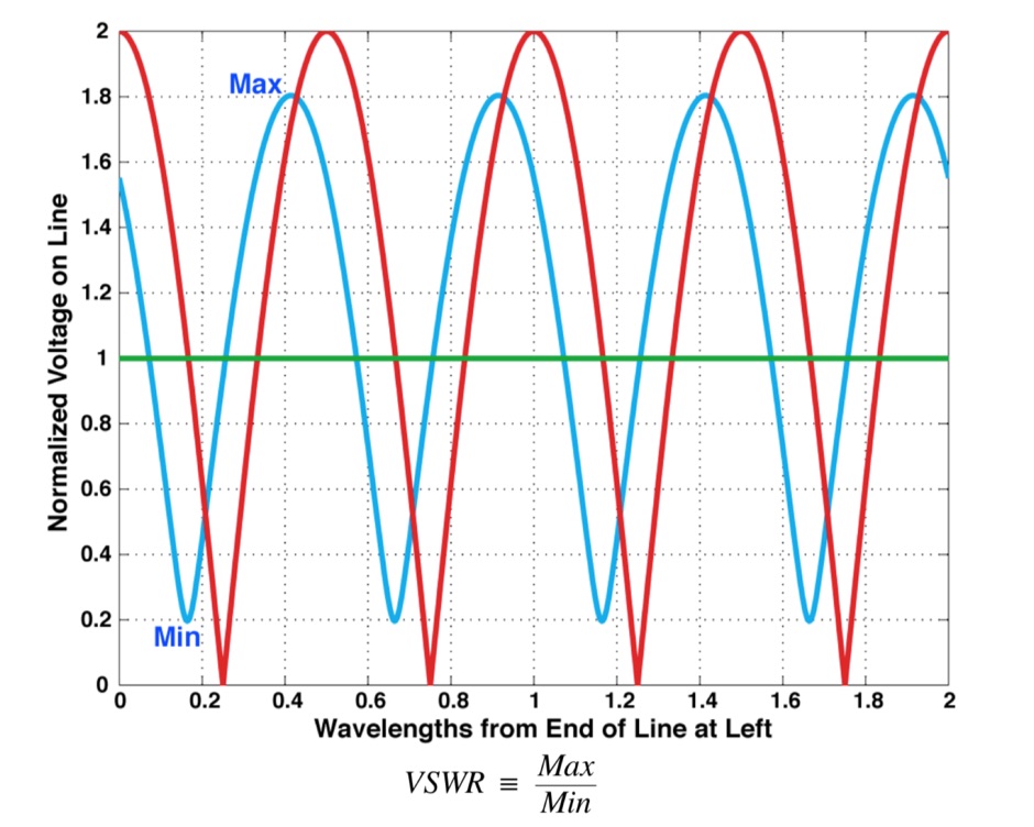 What is VSWR and why you should care, formal definition of VSWR and SeaSonde Measurements, formulas
 -
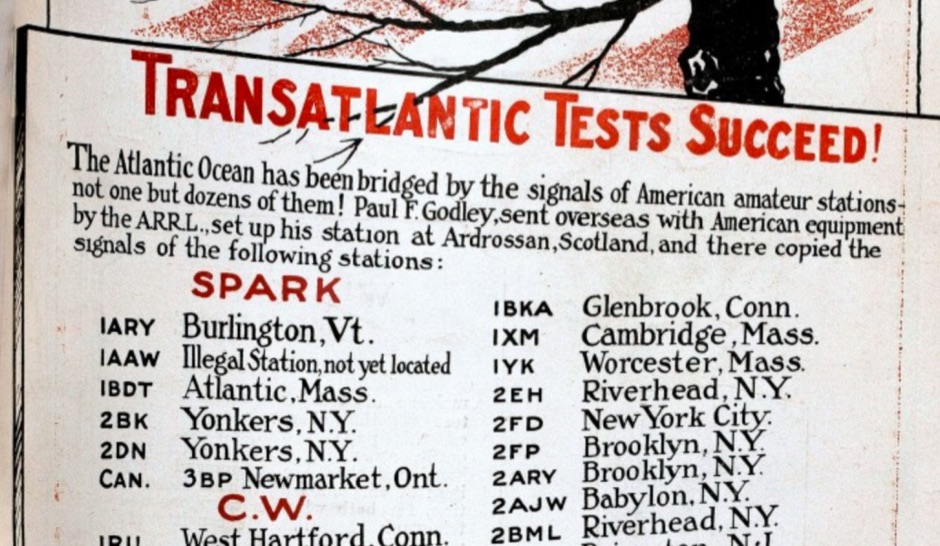 From 1921 to 1924, radio amateurs experimented with transmitting across the Atlantic. Everyday Engineering magazine organized the first sending test with English amateurs prepared to listen for signals from the US
 -
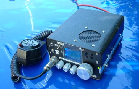
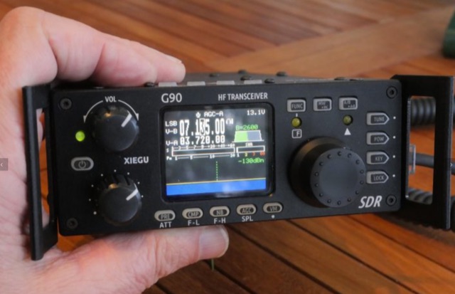 Review of the Xiegu G90 20W HF portable transceiver capable to run CW SSB AMD modes, based on an Software Defined Radio
 -
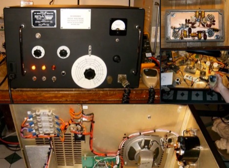
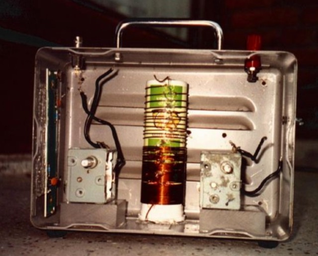
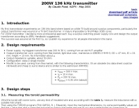 A transmitter project for the 136 kHz band by IK2PII
 -
 This article describes the construction of a high performance transmitter and receiver for SSB (voice) communication covering the 14MHz (20 meters) high frequency amateur radio band with output range 15 to 20 watts and a top audio sound quality both on transmit and receive.
 -
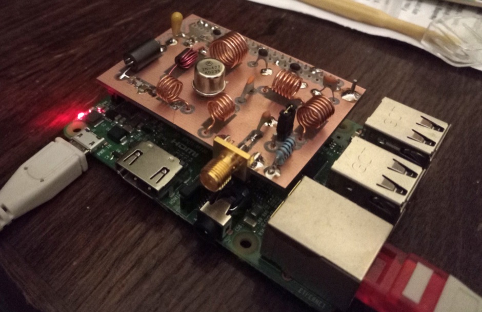 How to limit unwanted harmonics from your raspberry Pi radio transmitter by introducing filters.
 -
 With the new name TRANSRADIO, the former TELEFUNKEN SenderSysteme AG enters into the new digital age of Broadcasting – DRM.
 -
 Drake TR-7 A.M. Transmit Filter Modification
 -
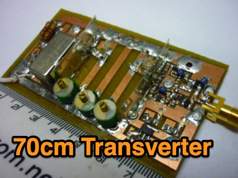
 A 70 MHz Transverter project with a block diagram and schematics
 -
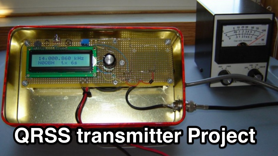 The N0QBH QRSS project page, a couple of projects using available kits for improved frequency and timing stability. A configurable DDS VFO 100mW transmitter with LCD display and a modified Hans Sommers 40m 100mW transmitter
 -
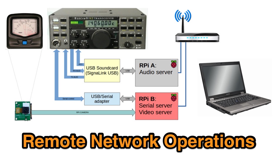 This is a page to detail how I remotely operate my Elecraft K2 HF transceiver via my home network. The method used should apply to pretty much any amateur transceiver that can be controlled by serial port.
 -
 Amateur Radio Transmitting Society located in Louisville, KY
 -
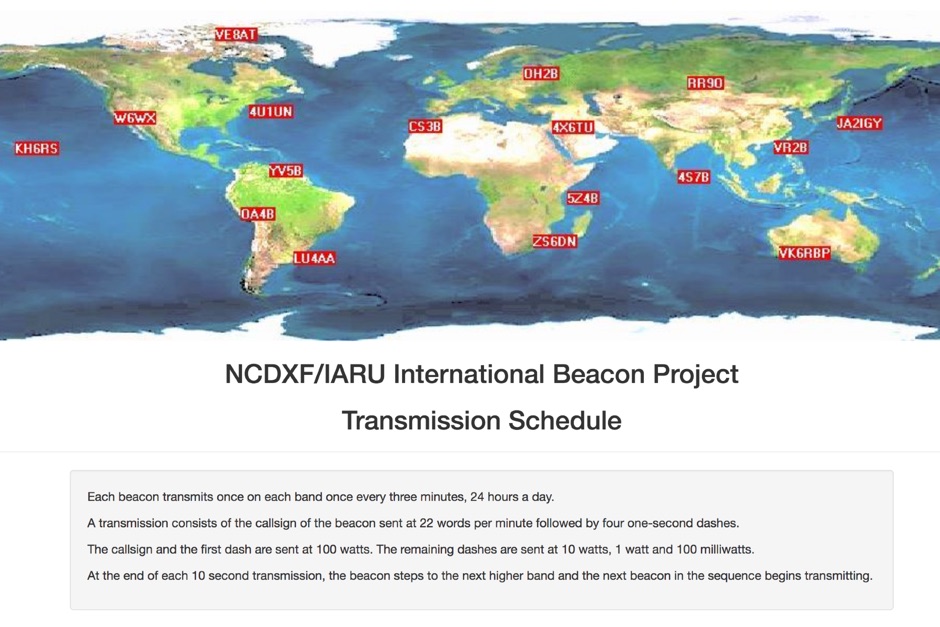 Whatch at beacons transmitting in real time. This page contains a self refreshing table that displays every 10 seconds the current transmission schedule of the international beacon project. Tune your radio and check the beacon you are hearing.
 -
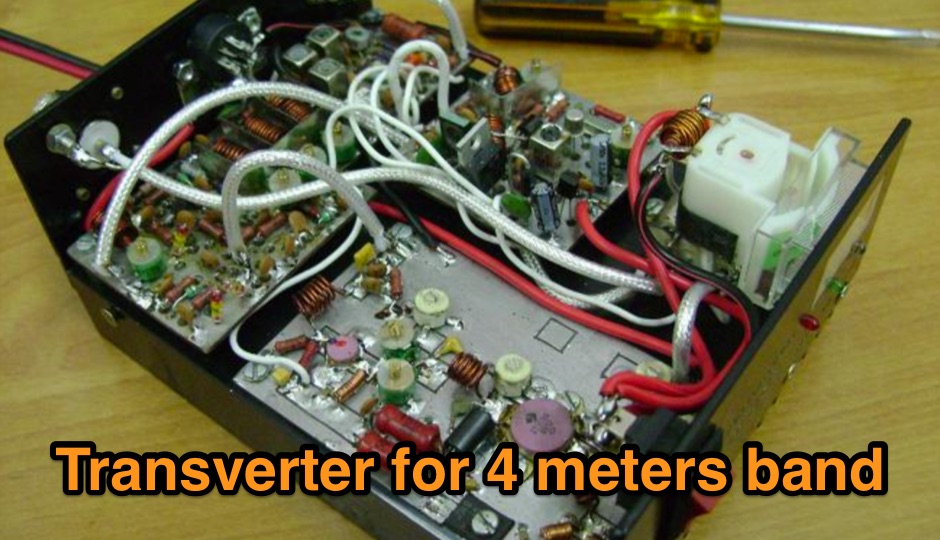
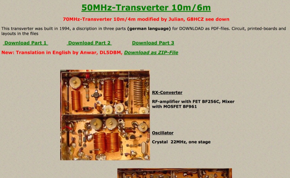 This transverter was built in 1994 and include in this page a pdf with circuit board, and a version of this project for 70MHz.
 -
 Constructing an End-Fed Half-Wave (EFHW) antenna offers a practical solution for HF operators seeking a multiband wire antenna without the need for extensive radial systems. This design typically employs a high-impedance transformer at the feed point, matching the antenna's inherent high impedance to a 50-ohm coaxial feedline. The article specifically details a 2012 approach, focusing on a transformer with a 49:1 turns ratio, which is a common configuration for EFHW antennas. The resource outlines the construction of a wire element cut for a half-wavelength on the lowest desired band, with specific coil arrangements enabling operation on harmonically related bands such as 40m, 20m, and 10m. It discusses the physical dimensions and winding details for the matching transformer, often utilizing a ferrite toroid core to achieve the necessary impedance transformation. The content provides insights into the operational principles and practical considerations for deploying such an antenna, including methods for tuning and optimizing performance across multiple amateur radio bands. While acknowledging that the presented information from 2012 may be superseded by newer insights, it serves as a foundational reference for understanding EFHW antenna theory and construction.
 -
 Use these Variac auto transformers for specific application requirements that include, but are not limited to, home coffee roasting, tube amps, and more.
 -
 While transistors have many uses, one of the less known uses by amateurs is the ability for bipolar transistors to turn things on and off
 -
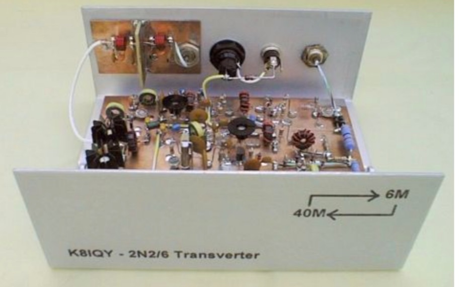 This project is a 40 meter to 6 meter CW "no tune" transverter using ten 2N2222 transistors and one 2N2907. The transverter requires 2 watts of drive from a 40 meter cw transceiver and outputs 2 watts on 6 meters.
 -
 How to build a complete Single-Sideband amateur radio transceiver from scratch. Article published on hackaday dot com includes an introduction to radio architectures, ssb receivers and tramsitter
 -
 Designed for portable operation, it runs on 12v, and has an OCXO-based local oscillator.
 -
 The current page presents a domain name for sale, rather than providing amateur radio content. It outlines the process for acquiring the _ae5x.com_ domain, including a direct purchase price of **$3,795** or a 24-month payment plan at $158.13 per month with 0% interest. The service emphasizes quick delivery, secure shopping via SSL encryption, and a 30-day money-back guarantee. Information regarding domain transfers to other registrars like GoDaddy is provided, noting that transfers can take up to 5 days and payment plan domains are ineligible until fully paid. The purchase includes only the domain name, with hosting and web design services needing to be sourced separately. Privacy protection options through NameBright.com are also mentioned.
 -
 The resource, "Conventional Use of Transmission Line," meticulously details the operational principles of transmission lines, emphasizing the Transverse Electromagnetic (TEM) mode of energy transfer. It clarifies that for a line to function purely as a transmission line, all currents must be confined internally, with external fields ideally zero. The discussion differentiates between balanced and unbalanced lines, asserting that while both require equal and opposite currents within the conductors, the key distinction lies in the voltage relationship of each conductor to the surrounding environment. It highlights that a good antenna pattern does not inherently confirm proper feeder balance, and that common-mode currents can lead to RF in the shack and increased noise levels, even without pattern distortion. The article further explains that a transmission line can become a radiating conductor if energy is applied in a non-TEM mode, leading to common-mode issues. It cites classic texts like Jordan and Balmain's "_Electromagnetic Waves and Radiating Systems_" and Kraus's "_Antennas_" to support its definitions of TEM mode operation. The content also explores non-transmission line applications of parallel or concentric conductors, such as _coaxial dipoles_ and _folded dipoles_, which intentionally operate in non-TEM modes for antenna functionality. The author, _W8JI_, stresses that simply measuring equal currents is insufficient to confirm a balanced feeder; phase and voltage balance to ground are equally critical.
 -
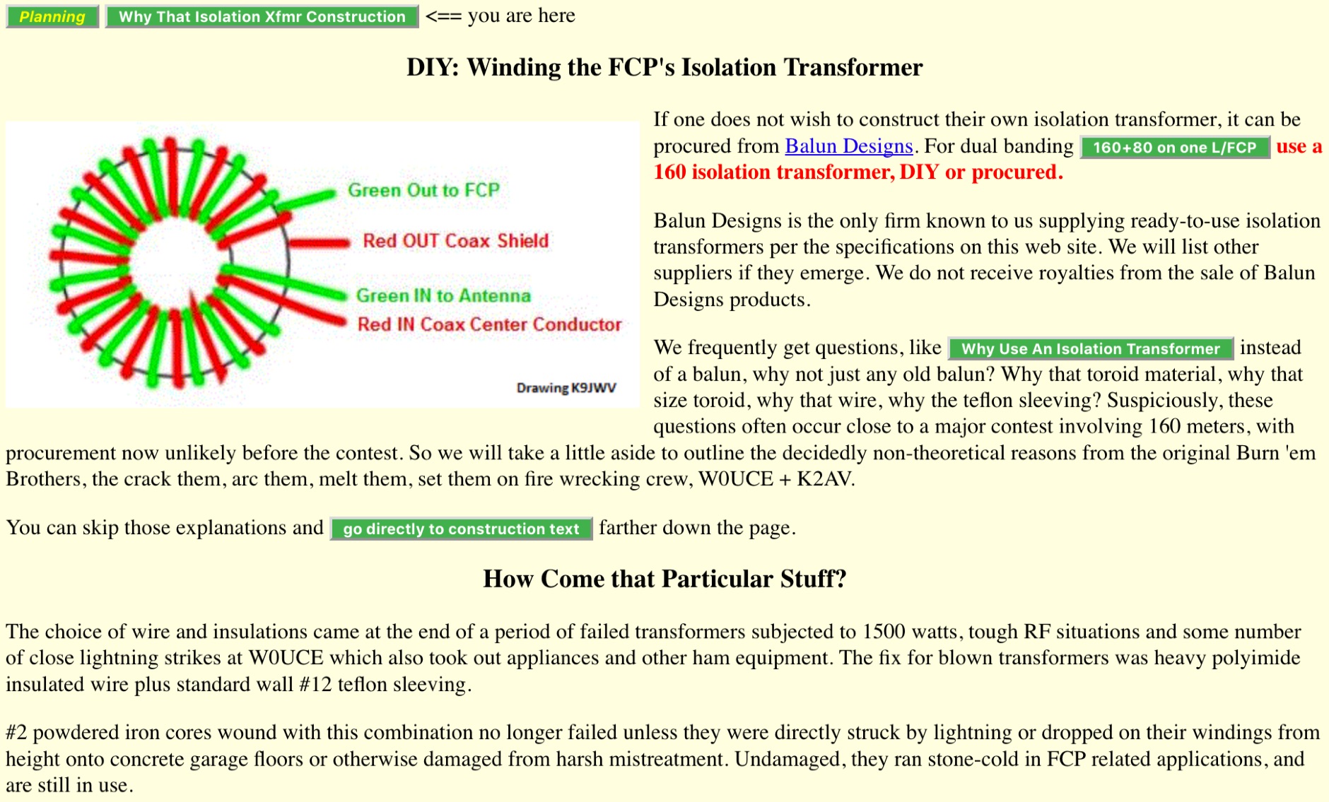 Article about isolation transformer construction to perform optimal impedance matching. Winding the FCP isolation transformer, includes interesting table for Winding Turns and Lengths and Core Configurations for T300 T200 T400 toroids
 -
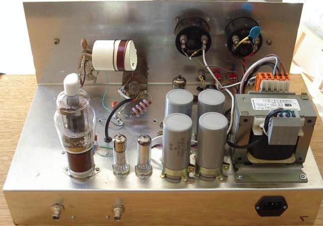
 Station QRP presents various **circuit diagrams** for constructing low-power AM vacuum tube shortwave transmitters, catering to enthusiasts interested in vintage radio technology. The resource details schematics ranging from simple to more complex designs, enabling hams to build their own QRP AM transmitters for operation on frequencies like 6.925 kHz AM. It emphasizes the use of vacuum tubes, providing a technical foundation for understanding and replicating classic shortwave broadcasting methods. The content is geared towards those who enjoy the hands-on aspect of electronics and the unique characteristics of tube-based RF circuits. Building these transmitters allows operators to experience the nostalgia of early shortwave radio, with the site specifically mentioning a pioneer station on 6.925 kHz AM. The designs facilitate experimentation with low-power AM transmission, offering practical application for homebrew projects. The focus on QRP (low power) operation aligns with a segment of the amateur radio community that values efficiency and minimalist setups, providing a distinct alternative to modern solid-state transceivers.
 -
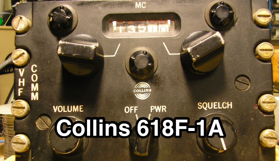 Restoring a 1965 Collins 618F-1A VHF aircraft radio. This radio was designed for light aircraft as an early frequency-synthesized radio built in 2 separate chassis.
 -
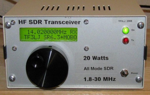 This project describes a DIY all band HF SDR transceiver. Built around a Softrock 6.3 kit, it boasts a 20W homebrew amplifier and ATmega168 microcontroller for USB control. An LCD displays frequency, power, and SWR. Automatic LPF selection and SWR protection enhance functionality. Compatible with Rocky and PowerSDR software, this project provides a cost-effective and powerful HF SDR transceiver for hobbyists.
 -
 Low-frequency (LF) radio time signals, operating primarily in the 40–80 kHz range, are broadcast by national physics laboratories for precise clock synchronization. Transmitters like **JJY** (40 kHz, 50 kW; 60 kHz, 50 kW), RTZ (50 kHz, 10 kW ERP), MSF (60 kHz, 15 kW ERP), WWVB (60 kHz, 50 kW ERP), RBU (66.66 kHz, 10 kW), and DCF77 (77.5 kHz, 50 kW) cover vast geographic areas, often several hundred to thousands of kilometers. LF signals offer distinct propagation advantages over higher-band transmissions such as GPS. Their long wavelengths (3–6 km) enable effective diffraction around obstacles like mountains and buildings. The ionosphere and ground act as a waveguide, eliminating the need for line-of-sight and allowing a single powerful station to cover extensive regions. Ground wave propagation minimizes ionospheric variability effects on transmission delay, and signals penetrate most building walls effectively. Robust and low-cost receivers, often priced at 20–30 USD/EUR, are widely used in radio clocks. These receivers typically comprise a tuned ferrite core antenna, a receiver IC (e.g., Atmel T4227, U4223B, MAS1016) for amplification and AM detection, and a microcontroller for decoding the time signal and phase-locking a local clock. Specific components for DCF77, MSF, and WWVB are readily available from vendors like HKW Elektronik and Ultralink.
 -
 On December 12, 1901, Guglielmo Marconi successfully received the first transatlantic wireless communication, a Morse code "S" (three dots), at 04:30 GMT. This article details the setup for this groundbreaking experiment, noting Marconi's receiver in St. John’s, Newfoundland, Canada, utilized a _coherer_ and an antenna elevated by balloons and kites. The transmitting station at Poldhu, Cornwall, England, featured twenty-four 200-foot ships' masts and a 25-kilowatt alternator. The resource explains how this contact disproved contemporary beliefs about radio wave limitations due to Earth's curvature, later understood through _ionospheric propagation_. It frames Marconi's achievement as the "very first DX" in amateur radio terms, defining DX as telegraphic shorthand for distance and _DXing_ as the hobby of receiving distant signals. The article also provides external links for further reading on Marconi's experiments and the science behind transatlantic radio signal reception.
 -
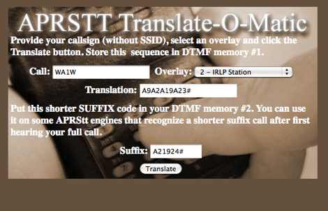 APRSTT translate-O-Matic convert online your callsign in DTMF
 -
 One common semiconductor material, silicon, is far more widely used in electronics than germanium, partly because it can operate at much higher temperatures. Semiconductors are crystalline materials with electrical resistivity values between conductors and insulators, whose conductivity can be altered through _doping_ with impurities like arsenic or phosphorous to create N-type (excess electrons) or P-type (electron vacancies) materials. Semiconductor devices, such as diodes, transistors, and integrated circuits, leverage these properties to control electron flow in circuits. A diode, a two-terminal device with an anode and cathode, primarily permits current flow in one direction, making it useful as a rectifier to convert AC to DC. Specialized diodes include Zener diodes for voltage regulation and Light-Emitting Diodes (LEDs) that produce light when current passes through them. Logic circuits, fundamental to digital electronics, have binary inputs and outputs, performing functions like AND, OR, and NOT gates, and can be constructed from various binary devices including solid-state diodes and transistors. A transistor is an active semiconductor device with at least three terminals (base, emitter, collector), capable of amplifying current. Integrated circuits (ICs), often called chips, are electronic circuits built on a semiconductor substrate, typically silicon. ICs are classified by transistor type (bipolar or MOS) and integration scale: Small-Scale Integration (SSI) with fewer than 10 transistors, Medium-Scale Integration (10-100), Large-Scale Integration (LSI) with 100-1,000, and Very-Large-Scale Integration (VLSI) with more than **1,000** transistors. ICs can be analog, digital, or hybrid, offering virtually limitless functions.
 -
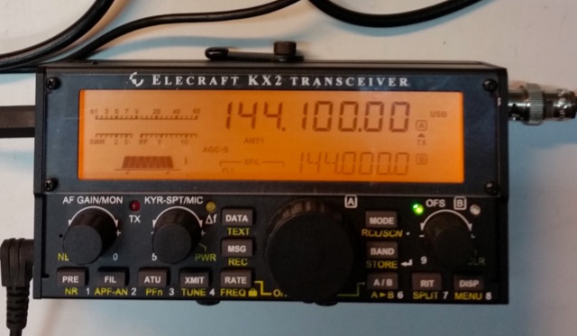 A 144 MHz transverter made by ur3lmz and connected to and Elecraft KX2 transceiver
 -
 Thsi article describes a microcontroller driven semi-automatic antenna tuner capable of handling power levels up to 150 watts. The device is a low pass filter tuner manually tuned by setting the optimized L/C combination by hand and then storing the values into the EEPROM of the mictrocontroller to recall them later (seperately for each band from 80 to 10 meters including WARC bands)
 -
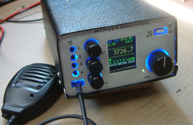 Gimme Five reloaded, a compact 5 band QRP SSB transceiver in SMD technology. This unit covers 5 bands within the amateur radio spectrum (3.5, 7, 14, 21 and 28 MHz). Receiver is a single conversion unit with an interfrequency of 9 MHz. Transmitter uses 5 stages and has got a power level of 10 watts PEP output.
 -
 This page is a detailed description of a 6CL6 and 807 valve transmitter. The page includes the complete circuit diagram to build this transmitter and several pictures
 -
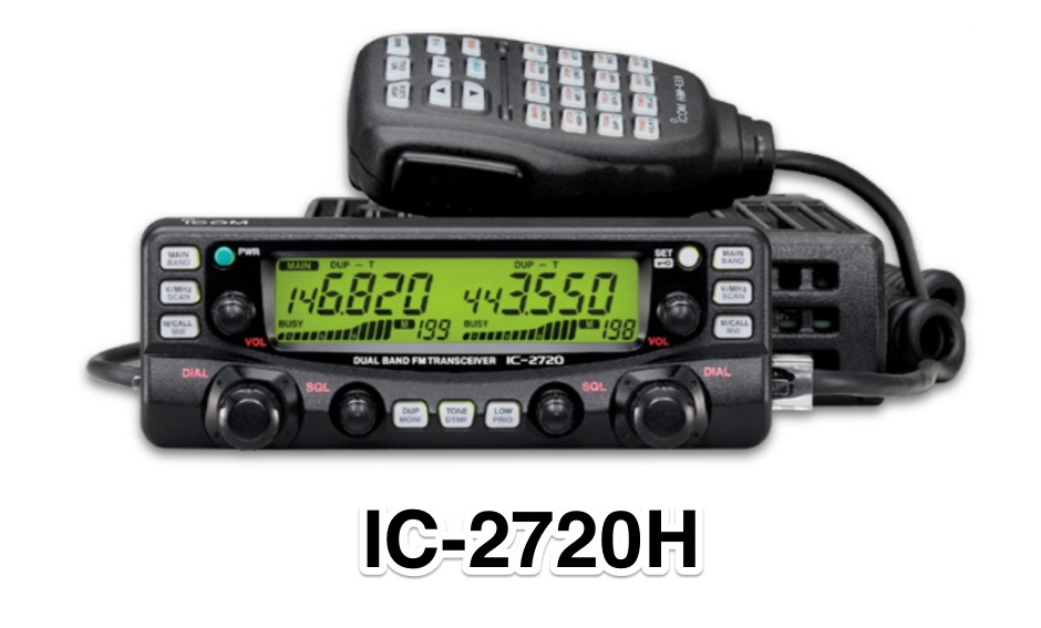 An interesting review of the Icom 2720H VHF UHF amateur radio mobile transceiver with pros and cons
 -
 The QCX 5W CW Transceiver From QRP Labs, a detailed article describing from the unboxing of the component to the final assembly of the CW QRP Transceiver
 -
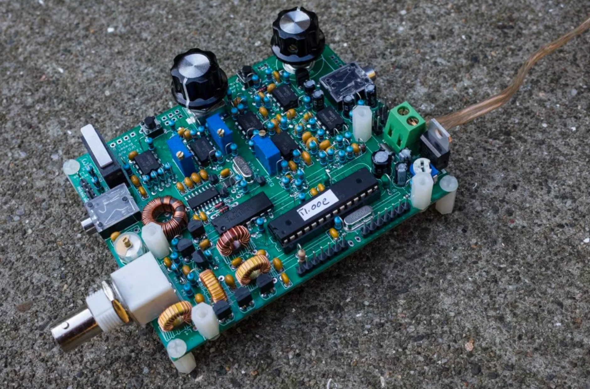
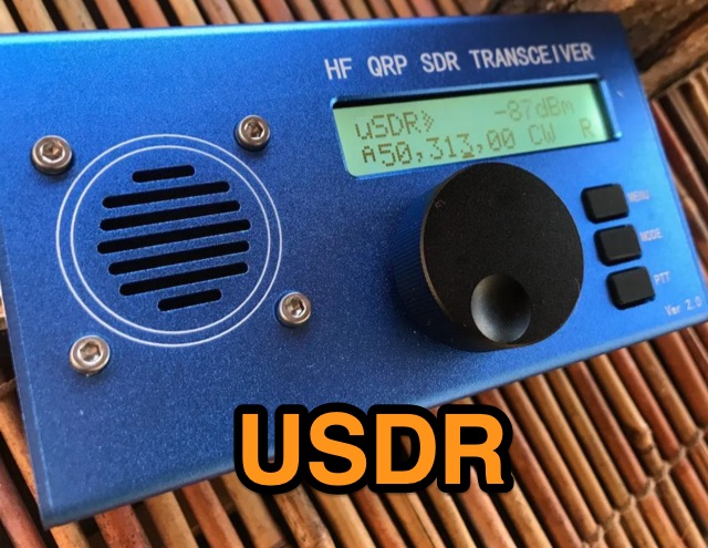 A review of the Chinese version of uSDX USDR HF QRP Transceiver. Author made an extensive review of receiver and transmitter features.
 -
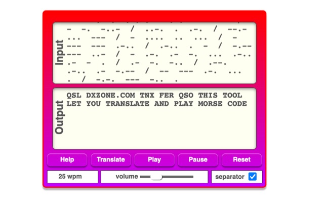 The online Morse code translator and decoder provides functionality for converting plain text into Morse code and decoding Morse code back into text. Users can input text directly into a designated box for translation to Morse, with the tool ignoring characters that lack a Morse equivalent. Conversely, Morse code can be entered using periods for dots and minus signs for dashes, requiring a single space to separate letters and a forward slash to delineate words. The interface also supports direct Morse input via a button, where a half-second pause separates letters and a 1.5-second pause separates words. The resource details the historical context of Morse code, noting its invention by _Samuel F.B. Morse_ in the 1830s for telegraphy, and its continued use by amateur radio operators for recreational purposes and emergency signaling, such as the **SOS distress signal**. Guidance on learning Morse code suggests using online translators for practice and listening to amateur radio transmissions. The tool offers an audio playback feature for translated Morse, allowing users to hear the code at various words per minute (WPM) settings. It also includes a visual chart to aid in memorizing the dot and dash sequences for the alphabet.
 -
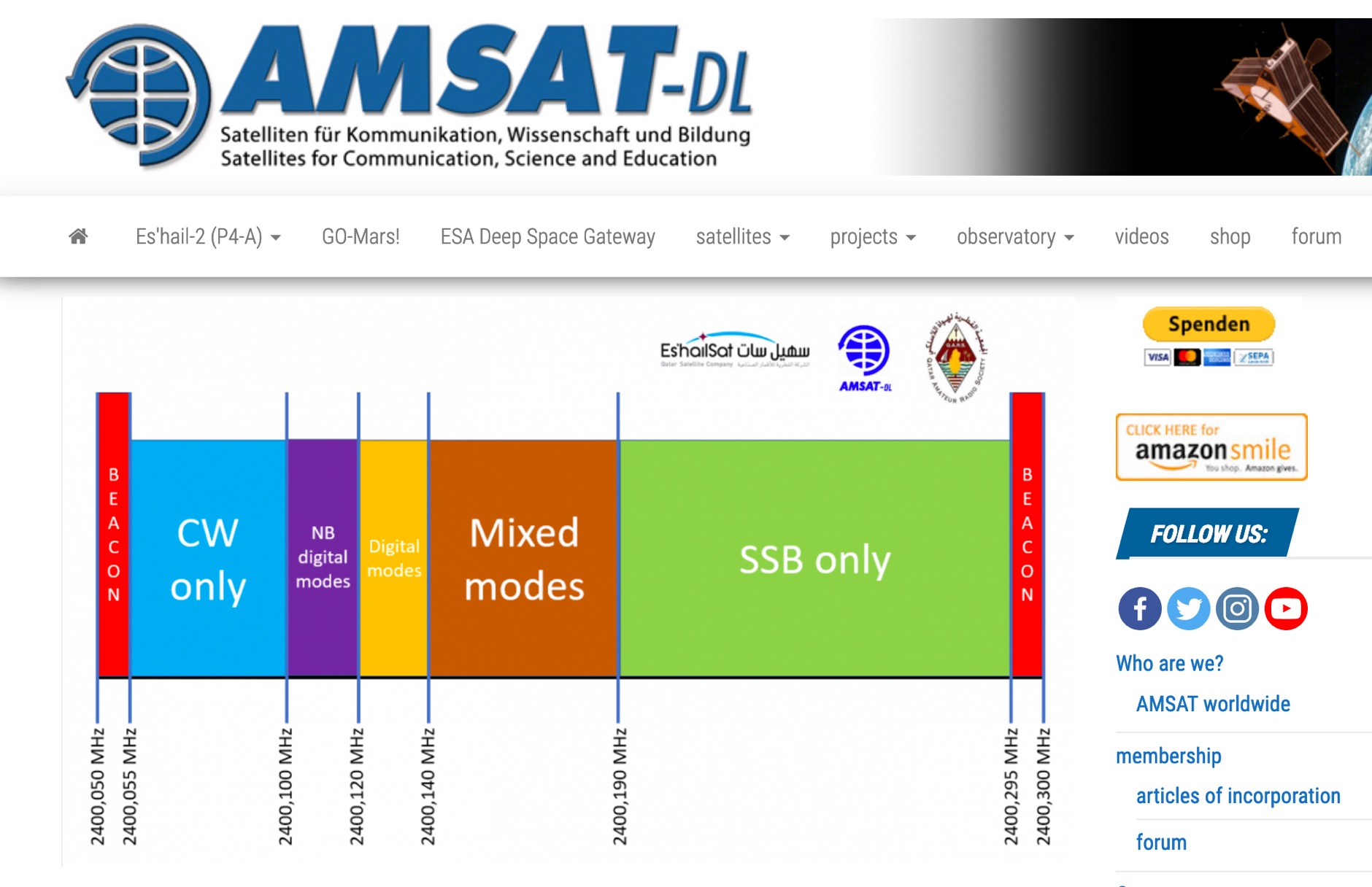 P4-A narrowband transponder Operating Guidelines and Band Plan, coverage map of the QO100 geostationary amateur radio satellite
 -
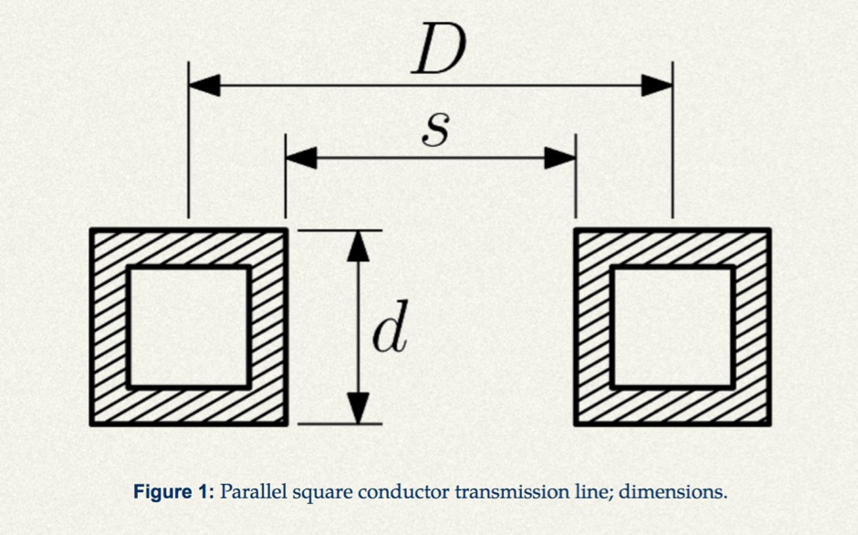 Design a parallel square stock balanced transmission line with this calculator.
 -
 The project in this article illustrates how to do this in a simple and low cost way so that you can easily access the microwave bands using the existing HF or HF/VHF transceiver as IF.
 -
 How test transistors and diodes with a simple digital multimeter.
 -
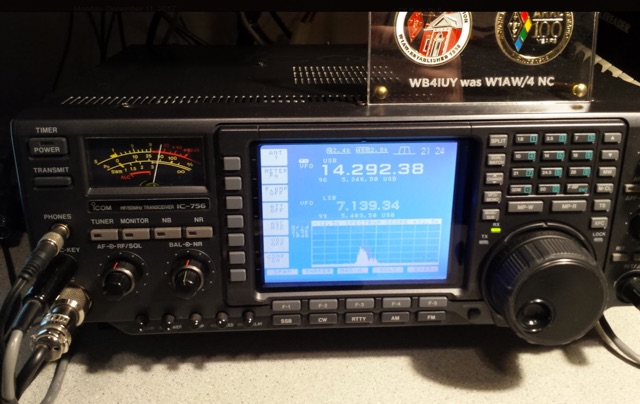 This article is about replacing the LCD display in a Icom IC-756 classic. The displays in these radios have not been supported by Icom in several years.
 -
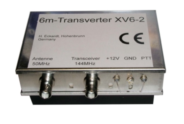 The XV4-10 is a linear transverter for the 4m band to be used with a 10m transceiver. Input frequency 29-30 MHz, output frequency 69.5-70.5 MHz
 -
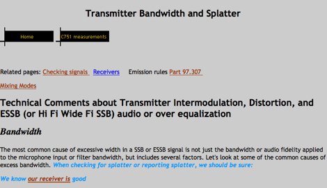 Technical Comments about Transmitter Intermodulation, Distortion, and ESSB (or Hi Fi Wide Fi SSB) audio or over equalization by W8JI
 -
 Mini-Operating Guide includes useful hints on Using the HM-133 Microphone, Basic Operation, Operating through a Repeater, Programming a Memory Channel and Assigning a Memory Channel to a Memory Bank
 -
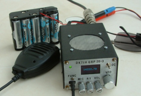 DK7IH QRP transceiver for 14 MHz. This small and compact home made transceiver with a max power output of 5W, the VFO module is based on the clock oscillator chip Si5351A by Silicon Labs ATmega168 and OLED 1306
 -
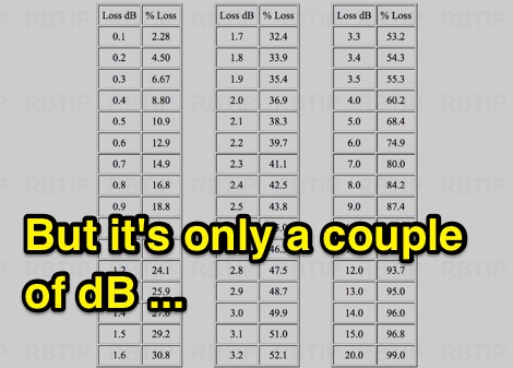 But it is only a couple of dB, The Effect Of Insertion Loss On Transmitted Power (dB to percentual loss) Original Information Provided by Neil McKie WA6KLA
 -
 A home made Antenna Tuner made with a simple inductor and a few spare parts. Despite the title, the author succesfully tested this ATU with higher power inputs.
 -
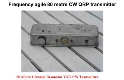 Frequency agile 80 metre CW QRP transmitter. Ceramic resonators vary in the frequency shift obtainable. The one in the prototype of this article gave 3.525 to 3.558 MHz coverage.