Search results
Query: 50 Mhz
Links: 403 | Categories: 8
Categories
- Operating Modes > 50 MHz
- Antennas > 6M > 6 meter Moxon Antennas
- DX Resources > Beacons > 6 meters beacons
- Antennas > 6M
- Radio Equipment > HF Transceivers > Icom IC-703
- Radio Equipment > HF Transceivers > Icom IC-7610
- Radio Equipment > HF Transceivers > Icom IC-7760
- Manufacturers > Antennas > VHF UHF Microwave > Microwave antennas
-
 Home made 40 meter transceiver project. The receiver is a Progressive Receiver with a few modifications. The Transmitter is a modified MFJ Cub circuit. Includes schematic and circuit diagrams for Receive Input Filter, 3-Pole 500 Hz Cohn Filter and 7 MHz Double Tuned Bandpass Filter
 -
 This multiband transverter project features power output at 13,8V 50MHz 15W, 70MHz 10W, second harmonic < 65dBc. Single N connector of antenna, suitable for a dual band Yagi. Article include Block Diagram for Dual Transverter and low pass filters
 -
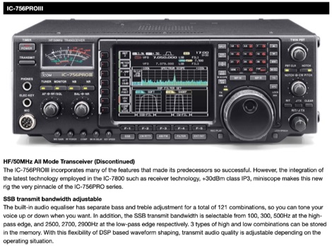 A page dedicated tho the IC-756PROIII transceiver. This radio, discontinued, incorporates many of the features that made its predecessors so successful. However, the integration of the latest technology employed in the IC-7800 such as receiver technology, +30dBm class IP3, miniscope makes this new rig the very pinnacle of the IC-756PRO series.
 -
 This project involves constructing a dual-band Moxon antenna, optimized for ham radio enthusiasts, with functionality on both the 10-meter and 6-meter bands. The antenna is designed to operate using a single 50-ohm feedpoint, acting as a mini-beam on 28 MHz (10 meters) and as a 2-element Yagi on 50 MHz (6 meters). Performance-wise, it offers a 4.0 dBd gain on 10 meters and 4.3 dBd on 6 meters, with impressive front-to-back ratios of 30 dB and 11 dB, respectively. Builders like Aleks (S54S) and Marcio (PY2OK) have successfully brought this design to life using the provided specifications. Aleks noted that bending the corners of the structure proved especially useful during assembly. The project comes with a detailed parts list, highlighting the use of aluminum tubes with different diameters and lengths to form essential components like the reflectors and radiators. For those looking to fine-tune the antenna, adjustments can be made by altering the length of certain parts that fit into larger tubes. The feeding system is equipped with a balun to accommodate different power levels, making the design versatile enough to handle outputs of either 300 watts or 1 kilowatt.
 -
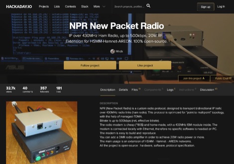 NPR (New Packet Radio) is a custom amateur radio digital protocol, designed by F4HDK to transport bidirectional IP trafic over radio links on the 70cm band. This IP protocol is optimized for point-to-multipoint topology, with the help of managed-TDMA. Bitrate is up to 500kbps. Home Made modem has a built-in ethernet port to connect to PC. To boost power a DMR amplifier is required to reach 20W. This project is an extension of HSMM - Hamnet - AREDN networks
 -
 A 14.12 dBi gain three elements cubical quad antenna for the six meters band. This Quad Antenna design page include a MMA model available to download and dimensions for each element.
 -
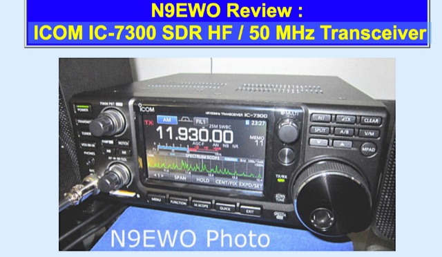 This page includes an interesting and comprehensive review of the ICOM IC-7300 SDR HF / 50 MHz transceiver. The author focuses on many aspects of this transceiver with impressions based on his experience
 -
 This is a design based on the QuickYagi 4 software by WA7RAI with some changes for practical reasons. The beam uses 6.5 metres of standard 25mm square boom, 12mm diameter elements without tapers. The actual boom length used is 6.3 metres and all parts are readily available.
 -
 In this article the author describes his personal experience on some antennas for 50 MHz he tested on the field, the six meter Dipole, Vertical, Moxon, a 3 element Yagi and an Omniangle antenna.
 -
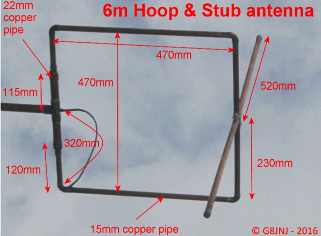 Omni-directional mixed polarisation antenna for 50MHz & 70MHz. This is a simple Halo and Stub antenna which provides an omni-directional radiation pattern with mixed polarisation, which I built for use with the SUWS WEB SDR
 -
 The 222 MHz Transverter project, based on Zack Lau's (W1VT) original July 1993 QEX magazine design, provides an IF of 28 MHz for both transmit and receive paths. Rick Bandla (VE3CVG) contributed supplemental notes and construction details, including modifications to achieve 10 mW output power from an initial 4 mW PEP. The design incorporates three distinct boards: a Local Oscillator (LO), a Transmitter (Tx), and a Receiver (Rx), with an estimated parts cost of just over $150 CDN, significantly less than commercial kits. Construction involves both through-hole and surface-mount components, with specific guidance on mounting MAV and MAR devices, grounding techniques, and component selection. The project details include parts lists, schematics for the LO, Tx, and Rx, and board layouts. Troubleshooting advice emphasizes sequential testing, starting with the LO, then Tx, and finally Rx, using a 194 MHz and 222.100 MHz capable FM handheld for signal tracing. Further enhancements are discussed, such as an optional Tx driver stage to boost output to 100 mW and the potential modification of a Motorola Maxor 80 PA for 222 MHz SSB/CW operation. The resource also covers practical aspects like power attenuation pads for IF radios (e.g., FT817) and considerations for enclosure design, including repurposing a Maxor 80 case. Performance reports indicate successful 70 km contacts with only 4 mW output.
 -
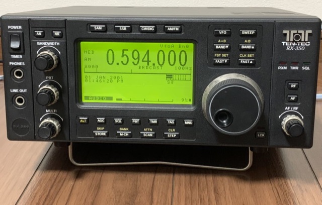 Review of the 150 kHz to 30 MHz Ten-Tec receiver
 -
 Presents a detailed construction guide for a 9 dB, 70cm collinear antenna, utilizing readily available _RG58/U_ coaxial cable and PVC pipe for housing. The resource outlines the critical calculations for ½ wavelength sections at 444 MHz, incorporating the coaxial cable's velocity factor of 0.66, which yields a section length of 223 millimeters. It specifies the preparation and soldering of eight such half-wavelength sections, each cut to 231mm to allow for trimming, forming the core of the array. Further instructions detail the integration of a ¼ wave element (169mm #16 solid wire) at the top and a ¼ wave aluminum tube (160mm, 5/16 inch) at the bottom, crimped to the feed point's braid. The guide also addresses RF common mode current suppression by suggesting the use of _FT50-43_ toroids on the feedline. Final assembly steps cover mounting the antenna within ¾" PVC pipe using a wooden dowel, waterproofing connections, and initial SWR checks. The article also discusses scaling the design for different element counts and other VHF/UHF bands.
 -
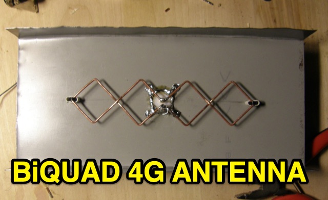 This is basic instructions for homemade 4G Antenna working on 2600 MHz UMTS featuring 13 14 dBi gain. This antenna is desigend to resonate on microwave frequencies in two segments from 2500 to 2570 MHz for Uplink, and from 2620 to 2690 MHz for Downlink.
 -
 This HF active antenna is a build of the PA0RDT Mini-Whip from a kit, it covers the entire HF band (3 to 30 MHz) and below (supposedly down to 10 kHz). It is powered by an external 12-15V supply, consuming about 50 mA.
 -
 This article details the author's process of designing and building a trap dipole antenna for the 17, 12, and 6-meter amateur radio bands using a Yaesu FT-450 transceiver. The antenna incorporates parallel-tuned circuit traps to enable operation across multiple bands without switching aerials. Key construction details, including coil and capacitor specifications, are discussed, along with the testing results, which include successful long-distance communications on the 50 MHz band. The article highlights the flexibility of home-built antennas and provides insights for amateur radio enthusiasts looking to optimize multi-band performance.
 -
 The PA0FRI Unbalanced/Balanced ATU is a home-built antenna tuner designed to efficiently match a W8JK 2-element beam antenna fed with a 450-ohm twin lead. Based on PA0FRI’s S-Match design, it optimizes energy transfer while maintaining balance, reducing losses, and ensuring proper radiation. The tuner uses a roller inductor, air variable capacitors, and a T200 iron powder coil, allowing fine-tuning across 14-50 MHz. Extensive lab tests confirm minimal attenuation and precise impedance matching, making it a reliable and efficient ATU for balanced antennas.
 -
 EA4EOZ details the construction and testing of 50 MHz traps, a critical component for multiband antenna designs. The project addresses the challenge of sourcing high-voltage capacitors suitable for trap applications, exploring alternatives to expensive doorknob capacitors. The author successfully fabricated a capacitor using 1.6mm double-sided FR-4 PCB material, achieving a capacitance density of **2.6 pF/cm2**. Utilizing the _VE6YP calculator_, specific L and C values of 30 pF and 0.31 uH were determined for a 2cm diameter coil. Both the FR-4 PCB trap and a coaxial cable trap, constructed from _RG-58_, were built and tuned to approximately 50 MHz using a spectrum analyzer. The coaxial cable trap demonstrated superior performance, exhibiting a notch nearly **20dB deeper** than the FR-4 version. This practical comparison provides insights into trap construction for experimental antennas, with the coaxial cable trap selected for an antenna project intended for operation at up to 100 watts.
 -
 This DIY Yagi costs less than 20 Dollars, and let you increase the performance of your connection. With this project you can build a better Yagi beam antenna resonant on 850MHz, a 8 element yagi directional antenna
 -
 This is a 50 MHz WebSDR receiver, located in Ashford, CT, USA FN31VU using a deltaloop turnstile horizontally polarized omnidirectional antenna.
 -
 The LKJ Wednesday Night Special Antenna, designed by John Whiteman K5LKJ, is a compact 50-foot coil-loaded dipole for 80-meter operation, ideal for space-limited hams in residential areas. Using two 1-inch diameter PVC coils with 87 turns of #16 magnet wire each—placed 10 feet from the center—it tunes to 3.910 MHz for local nets like BVARC Rag Chew. Constructed with #14 wire, ceramic insulators, and Mini-8X feedline, it handles 1000W, performs well at low heights for NVIS, and requires a tuner for bandwidth. Collaborative tuning by club members ensured success.
 -
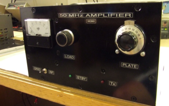 This project addresses the need for a 50 MHz Amplifier providing substantial power for Australian "Advanced Licensees" permitted to use 400W PEP in the 52-54 MHz band. In regions limited to 100W PEP due to TV channel usage, this initiative aims to enhance power output for transceivers with lower capabilities on the 6m band.
 -
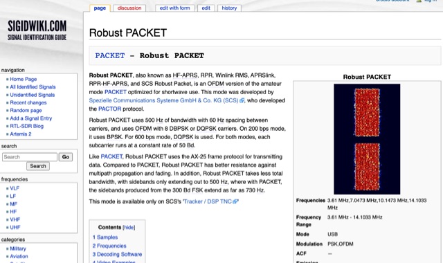 Robust PACKET, developed by Spezielle Communications Systeme GmbH & Co. KG (SCS), is an OFDM variant of the amateur PACKET mode specifically engineered for HF operation. This mode utilizes a 500 Hz bandwidth with 60 Hz carrier spacing, employing OFDM with 8 DBPSK or DQPSK carriers. It supports 200 bps using BPSK and 600 bps with DQPSK, with each subcarrier operating at a constant rate of 50 Bd. Robust PACKET leverages the AX-25 frame protocol for data transmission, similar to standard PACKET. Compared to traditional PACKET, Robust PACKET demonstrates enhanced resilience against multipath propagation and fading effects, critical for reliable HF communications. It also exhibits a more efficient spectral footprint, with sidebands extending only to 500 Hz, whereas 300 Bd FSK PACKET can produce sidebands up to 730 Hz. Operational frequencies for Robust PACKET include 3.61 MHz, 7.0473 MHz, 10.1473 MHz, and 14.1033 MHz, with specific regional frequencies also documented. Decoding software options for Robust PACKET include Wavecom W-Code and Wavecom W-Spectra. The mode is primarily supported by SCS's 'Tracker / DSP TNC' hardware.
 -
 Manufacturer of 50MHz, 70MHz, 144MHz, 222MHz, 432MHz, 900MHz or 1.2GHz transverters and VHF UHF amplifiers
 -
 The Beverage on Ground (BOG) antenna offers ham radio operators a compact alternative to traditional Beverage antennas, requiring less space and fewer support structures. This implementation, optimized for 1.8-7 MHz bands, describes ideal parameters: lengths of 60-90 meters, height of 2-10 cm above ground, and specific load resistances based on configuration. The article details experimental methods for determining optimal load resistance and presents matching systems to convert BOG impedance to 50 ohms. While less effective than classic 200-300 meter Beverages, the BOG provides directional reception in limited space, though performance varies with ground conditions and weather changes.
 -
 Paul McMahon details the design and construction of a four-element Yagi antenna for the 50-52.5 MHz range, published in Amateur Radio Magazine (Dec 2011). The antenna, featuring a raised driven element and a capacitive/DC connection using copper strips, maintains consistent VSWR and performance despite two years of weather exposure. The design utilizes inexpensive plumbing conduit for the boom and provides detailed construction guidelines, parts lists, and performance analysis through 4NEC2 simulations.
 -
 The resource details the construction of a J-pole vertical antenna specifically engineered for motorcycle mounting, addressing the common issue of interference with top cases. It outlines the fabrication process, beginning with an aluminum angle bracket for secure attachment to the lateral support, followed by the creation of the antenna's base from an 8mm threaded rod bent into a U-shape, approximately **40mm** wide. The article specifies the precise method for coaxial cable connections using eyelets and 3mm screws, ensuring robust contact. Further construction steps involve fitting a 10mm aluminum tube onto the threaded rod, with a screw securing the radiating element and establishing core contact. The design prioritizes mechanical stability against vehicle vibrations over fine-tuning SWR with sliding collars. Initial testing yielded a _SWR_ of **1.2** across a significant portion of the band, with improvements noted by optimizing the coaxial braid contact point near the support bracket. The document provides practical insights into material selection and assembly, emphasizing durability for mobile operation. It concludes with aesthetic options, allowing the builder to paint the antenna or retain its natural aluminum finish, making it a functional and adaptable solution for UHF motorcycle communications.
 -
 The resource details the construction of a 433 MHz LoRa APRS iGate and a tracker, both built around _TTGO T-Beam v1.1_ microcontroller boards. Each board integrates an OLED screen, WiFi, GPS, and an SMA antenna connector, powered by an 18650 3.7 V lithium-ion battery or microUSB. The iGate operates on 433.775 MHz, with its status verifiable on aprs.fi, demonstrating practical implementation of LoRa-based APRS solutions. The methodology involves programming the modules using Visual Studio Code with the PlatformIO plugin. This process loads the necessary firmware and a JSON configuration file, which includes the operator's callsign and WiFi credentials for the iGate. The guide emphasizes the ease of programming and provides specific steps for configuration. Initial testing of the iGate and tracker, including smart beaconing configuration, is documented. The low power output of approximately 200 mW from the LoRa board's transmitter is noted, with suggestions for range extension through improved antennas or RF amplification. The author, N4MI, plans to deploy a higher-gain 70cm antenna for the iGate.
 -
 The Pikes Peak Radio Amateur Association (PPRAA) serves as an ARRL Special Service Club, providing a calendar of events and activities for its members and the wider amateur radio community. The resource details upcoming events such as the USS Pueblo Memorial Museum Ships Weekend activations, a Cubical Quad Antenna Workshop, LARCFest, and various hamfests including Dayton Hamvention and Duke City Hamfest. It also lists on-air activities like a FreeDV digital voice mode event on 10 meters, a Black Friday Simplex Event on 2M and 70cm, and a 10m event for Technician class operators, emphasizing SSB privileges from 28.300 to 28.500 MHz. The PPRAA's event schedule includes educational opportunities like a Technician Class and a Soldering Workshop, alongside social gatherings such as the PPRAA Picnic and Car Show. Past event summaries highlight successful activities like the 2024 Megafest Raffle, Winter Field Day, and multiple fox hunts utilizing frequencies like 147.420, 147.480, and 147.540 MHz. The club actively supports POTA activations, exemplified by their AF0S park activation at Cheyenne Mountain State Park, and participates in historical commemorations like the USS Pueblo Memorial operations, demonstrating a broad engagement across various amateur radio facets.
 -
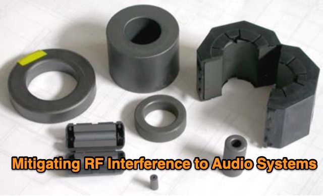 In this study, the author builds upon Muncy's research, demonstrating that radio-frequency current on cable shields affects audio systems through the "pin 1 problem" and shield-current-induced noise (SCIN). An enhanced equivalent circuit for ferrite chokes is proposed, addressing dimensional resonance and inductor self-resonance. Field tests confirm that chokes reduce interference across 500 kHz to 1,000 MHz. Guidelines for diagnosing and mitigating EMI from various sources are provided for product development and field installations.
 -
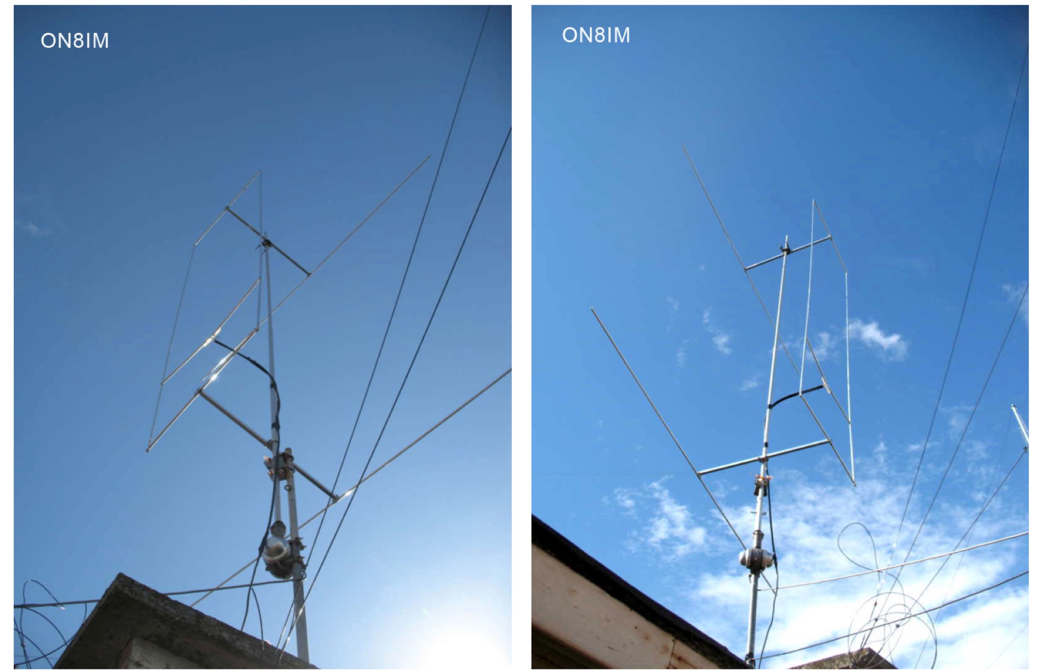 Explores the addition of a reflector to the traditional Hentenna design for 6m band, providing construction insights, performance comparisons, and modeling data
 -
 Amateur radio website dedicated to six meters band with dedicated pages on 50MHz propagation and DXing
 -
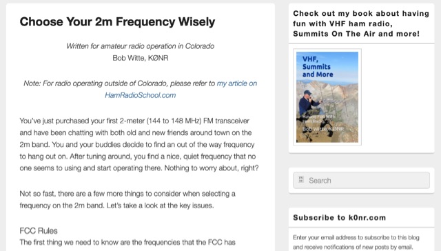 When new to the 2-meter FM transceiver, securing a quiet frequency for chatter seems straightforward, but it's essential to navigate FCC rules and band plans effectively. Even though frequency allocations are consistent above 50 MHz for Technician licenses, adherence to specific segments within the 2m band—ranging from 144 MHz to 148 MHz—is crucial. This includes respecting designations for different modes like CW, SSB, and FM to prevent interference, particularly with satellites and exotic modes like EME. Understanding and following the structured band plans not only ensures legal compliance but also optimizes frequency use and minimizes disruptions in the amateur radio community.
 -
 Fifty-one MHz operation, often called the "magic band," benefits significantly from a well-designed antenna, and this resource details the construction of a rigid 6-meter _Moxon antenna_ using common DIY store materials. The author, 4L/G8BAG, shares his experience with the 6m band, highlighting its potential for long-distance contacts, with single-hop sporadic E propagation enabling QSOs up to **2,500 km** and multi-hop contacts reaching **10,000 km**. The project emphasizes cost-effectiveness and durability, utilizing yellow gas pipe with an internal stainless steel lining for the antenna elements. The article provides specific dimensions for the Moxon rectangle, derived from the 12mm internal diameter of the gas pipe's steel core, rather than the outer plastic. It also details the use of white PVC water pipe for insulators and mounting, ensuring a tight fit with the yellow gas pipe. Initial testing with an MFJ antenna analyzer showed an excellent 1:1 SWR across the 50-52 MHz range, even when using 75 Ohm satellite cable as a feeder. The construction process is straightforward, involving cutting and bending the gas pipe, fitting insulators, and connecting the feedline. The author's successful on-air results, including a 1000 km contact with a temporary vertical, underscore the effectiveness of the 6m band and the Moxon design. The resource concludes with a note on exploring heavier gauge gas pipe for future 10m antenna projects.
 -
 The Central States VHF Society, Inc. (CSVHFS) is a not-for-profit organization chartered in the state of Missouri. It was begun in the mid-1960s to foster amateur radio operation on the bands above 50 MHz.
 -
 An FT-817 ceased transmission on the VHF 2m band, despite the other HF, UHF, and 50 MHz bands operating correctly. Suspecting an excess of input signal during FT-8 mode transmission, they conducted measurements with an oscilloscope, revealing a burnt-out PIN diode, identified as D3003, type HSU277, on the PA unit board. Following the replacement of this surface-mounted diode, their FT-817 resumed operation on the 144 MHz band.
 -
 The _MFJ-915_ RF Isolator, rated for 1.8-30 MHz and 1500W PEP, exemplifies the product range available from The Ham Shop. The inventory includes various antenna support ropes, such as 3/16" _Dacron Polyester Rope_ in lengths from 100 to 1500 feet, alongside a selection of cables for _SignaLink USB_ sound card interfaces. Specific SignaLink cables are offered for radios like the Yaesu FT-847 (SLCAB847), Yaesu HTs (SLCABVXY), and the Elecraft K3 (SLCABHTY). Additionally, the shop provides modular jumper cables and modules, including the SLMOD8RY for Kenwood/Alinco 8-pin round mic jacks and the SLMOD8RI for Icom 8-pin round mic jacks. The product line supports diverse station configurations, encompassing antennas, coax, baluns, dummy loads, duplexers, insulators, microphones, power supplies, SWR meters, and watt meters.
 -
 This project documents the construction of a coaxial 50 MHz notch filter to eliminate inter-band interference between 50 and 70 MHz transceivers. Using RG-213 coax and based on quarter-wave stubs, the filter achieved a 44 dB attenuation at 50.060 MHz while maintaining low insertion loss on 70 MHz. A dual-stub design broadened the notch response and minimized attenuation on 70 MHz to 0.2 dB. Fine-tuned using an FA-NWT network tester and Elecraft XG3 signal source, the filter effectively resolved interference for seamless dual-band operation.
 -
 Official English Brochure by ICOM of the IC-7760 HF and 50 MHz 200W Power output, transceiver. PDF File
 -
 This resource details the construction and performance of a compact broadband magnetic loop antenna designed for portable receiving applications with devices like the _ATS MiniRadio_. The antenna utilizes approximately 3 meters of 0.5–1 mm copper wire wound in two turns on a rhomboidal wooden frame, measuring 50 cm by 70 cm. It connects via a modified 9:1 unun, where the primary center tap is isolated from ground to improve common-mode noise rejection. The design provides untuned operation across a frequency range from the longwave band up to approximately 25 MHz. Performance characteristics include observable directivity for noise suppression and the ability to connect directly to a radio or via a 50 coaxial cable for remote operation. The article specifies the unun's 3:1 turns ratio and its SMA output for connectivity. The methodology focuses on practical construction and observed reception quality.
 -
 Guide to constructing an effective antenna for 50MHz. Inspired by a design from Martin DK7ZB, the article emphasizes the importance of precise measurements and quality materials. With a 2.20m boom and careful assembly, the antenna promises excellent performance, resilience, and cost-effectiveness, making it ideal for six meter band operations.
 -
 This paper presents an 80 meter wire 3-element beam antenna in an inverted-V configuration, designed for limited-height towers. Using EZNEC modeling, the antenna features a central parasitic reflector and two switchable driven elements at each end, enabling NE/SW coverage without moving parts or networks. Element lengths are optimized for SSB (3.8 MHz) and CW (3.5 MHz) operation, with a 50 Ω feed and rope-supported boom. The design delivers high gain, effective takeoff angles, and excellent reception, confirmed in real-world DX contest operation. Its simplicity, reliability, and ease of construction make it ideal for operators seeking performance without complex matching systems.
 -
 This paper by Leif Asbrink (SM 5 BSZ) presents a practical approach to designing very high gain Yagi antennas, focusing on the "brute force" optimization method. The method, described in a previous article, ensures convergence independent of initial guesses. The paper provides detailed tables of element lengths and positions for Yagi antennas optimized for 144.1 MHz with a 50-ohm feed point impedance, aiming for minimal losses and high accuracy in comparisons.
 -
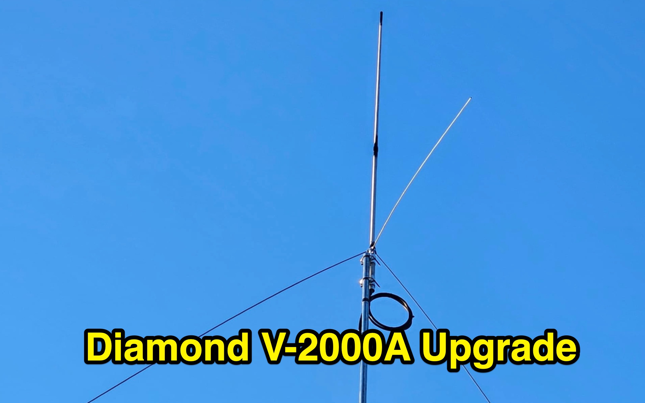 Learn how to enhance the performance of your Diamond V2000A antenna by optimizing the length of the radials. Discover a cost-effective method to create improved radials using simple materials like aluminum tubes and bolts. Explore the benefits of this modification for 6m band, unlocking triband capabilities and better SWR. Find out how a ham radio operator from Europe successfully upgraded their V2000 antenna and achieved impressive results. Save money by DIY-ing your radial enhancements instead of purchasing expensive replacements.
 -
 The Olivia digital mode, a **Multi-Frequency Shift Keying (MFSK)** radioteletype protocol, is specifically engineered for robust communication under difficult propagation conditions on shortwave radio bands from 3 MHz to 30 MHz. Developed by Pawel Jalocha in 2003, Olivia signals can be decoded even when the noise amplitude exceeds the digital signal by over ten times, making it highly effective for transmitting ASCII characters across noisy channels with significant fading and propagation phasing. Early on-the-air tests by Fred OH/DK4ZC and Les VK2DSG on the Europe-Australia 20-meter path demonstrated intercontinental contacts with as little as one-watt RF power under favorable conditions. Common Olivia modes are designated as X/Y, where X represents the number of tones and Y is the bandwidth in Hertz, with examples including 8/250, 16/500, and 32/1000. The resource clarifies that Olivia, unlike some other digital modes, produces a constant envelope, allowing RF power amplifiers to achieve greater conversion efficiencies and making it less prone to non-linearity. Operators are advised that **Automatic Level Control (ALC)** can be set higher than no meter movement for MFSK modulation, as long as it's not driven past its high limit, contrary to common misinformation about other digital modes. The Olivia community encourages voluntary channelization on suggested calling frequencies, such as 14.0725 MHz for 8/250, to facilitate initial contacts, especially for signals below the noise floor. The Olivia Digital DXers Club provides links to Groups.io, Facebook, and Discord for community engagement and offers details on QSO parties.
 -
 This article describes the implementation and testing of a low-power GPS tracker using LoRa technology in the 433MHz amateur band. The system, built with AIThinker RA-02 modules and Arduino controllers, demonstrated successful communication over non-line-of-sight distances up to 5km. Operating with a 125kHz bandwidth and spreading factor of 11, the tracker achieves a data rate of 500 bits/sec. Powered by a LiPo cell with power-saving features, the final compact design operates for approximately 1.5 weeks between charges with 3-minute reporting intervals, consuming just over 1mA in idle mode.
 -
 Assessing the ICOM IC-R9000 communications receiver, this review details its operational parameters and user experience for radio enthusiasts. Introduced in 1985, the IC-R9000 covers a broad frequency spectrum from 0.1 MHz to 1999.8 MHz, making it suitable for a wide array of listening activities from medium wave (MW) to VHF/UHF. Key performance metrics include a dynamic range of **102 dB** with the narrow SSB filter, crucial for discerning weak signals in crowded bands, and its substantial physical dimensions of 424 x 150 x 365 mm and 20 kg weight. The receiver's architecture supports various modes, though it notably lacks synchronous detection, a feature often desired for improved AM reception under fading conditions. It incorporates 1000 memory channels and robust scanning capabilities, facilitating efficient monitoring across its extensive frequency range. This analysis provides insights into the IC-R9000's capabilities and limitations, offering a historical perspective on a significant piece of amateur radio and shortwave listening hardware.
 -
 The **Yaesu FRG-100** shortwave receiver, introduced in 1992, operates across a frequency range of 50 kHz to 30 MHz, accommodating AM, LSB, USB, and CW modes, with an optional narrow-band FM capability. Its physical dimensions are 238 x 93 x 243 mm, with a weight of 3 kg, making it suitable for both portable and fixed station deployments. Power options include standard mains voltage or 12VDC, providing operational flexibility for diverse listening environments. The front panel integrates a manual tuning knob, an analogue signal strength meter, and an LCD display that provides critical information such as frequency, operating mode, memory channel, and time. Users can configure various operational parameters, including tuning steps and bandwidth filters, to optimize reception for specific signals. This review highlights the FRG-100's straightforward interface and its utility for shortwave listening enthusiasts. The design emphasizes user-friendly adjustments for settings, which contributes to its appeal among those interested in general coverage reception.
 -
 The FF-501DX LPF, a high-performance VHF and 10m filter, was obtained at a friend's SK sale. After becoming more active on 10m, the author reexamined the LPF and discovered it to be of high quality. The filter's efficiency was outstanding and the return loss/VSWR was better than estimated. The LPF was connected to a Bird 50R dummy load to evaluate insert loss, cutoff, attenuation over 70MHz, and return loss. The original specifications were found in an old radio magazine, along with a link to the original one-page information sheet. Comparing the results to the original specs confirms the LPF's quality.
 -
 The project aims to create a remote control system for the VK5RSE beacons located near Millicent, South Australia. The beacons on 144.550, 432.550, and 1296.550 MHz can interfere with nearby amateur radio operations, particularly for EME work on 1296 MHz. The remote control system uses a DTMF decoder and PIC microcontroller to allow turning the beacons on and off individually or in combination. The system is housed in a diecast box and powered from 5-8V. The password-protected control allows authorized users to manage the beacon operations remotely, helping mitigate interference issues for local amateurs.