Search results
Query: Dipole
Links: 614 | Categories: 15
Categories
- Antennas > 20M > 20 meter Dipole Antennas
- Antennas > 40M > 40 meter Dipole Antennas
- Radio Equipment > HF Portable Antenna > Buddipole
- Antennas > Dipole
- Manufacturers > Antennas > HF > Dipole Antenna
- Antennas > Fan Dipole
- Antennas > Folded Dipole
- Antennas > Resonant Feedline Dipole
- Antennas > 15M
- Antennas > 30M
- Shopping and Services > Antennas
- Manufacturers > Antennas > HF
- Antennas > T2FD
- Antennas > W3DZZ
- Antennas > Wire
-
 An economical dipole for simple QRP HF homebrew rigs
 -
 The T-Match with its balanced feed point is one method of feeding a Balanced Dipole.
 -
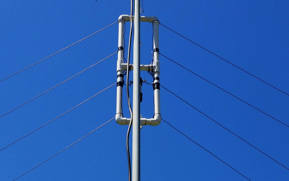
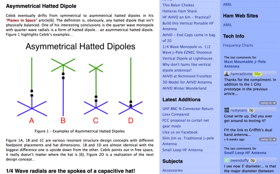 Theory and origins of W4RNL Asymmetrical Hatted Vertical Dipole AHVD for portable operations.
 -
 During a club's "Filetto Day" event, a comparative field test was conducted between a **Buddipole** antenna and a homemade 20/40-meter wire dipole. The author, IW5EDI, performed this personal evaluation from a mountain top at 1500 meters above sea level, utilizing a Yaesu FT-857D transceiver to switch between antennas. The observations on the 20-meter band indicated that the wire dipole consistently delivered significantly stronger signals compared to the Buddipole. Additionally, the Buddipole exhibited higher levels of **QRM** during the listening tests. The commercial Buddipole, known for its multiband capability and compact size with a self-supporting tripod, was contrasted with the simpler, larger wire dipole, which required a fiberglass fish pole for support. This direct comparison highlights practical differences in performance and deployment between a popular portable commercial antenna and a basic wire antenna in a real-world operating environment.
 -
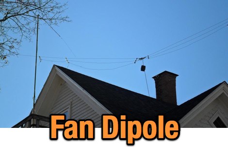
 There are a large number of antenna designs for HF. One choice out of many is the fan dipole. The ability to transmit of multiple bands without needing a tuner (and even more with a tuner) is a very desirable factor in choosing a versitle antenna for HF.
 -
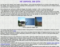
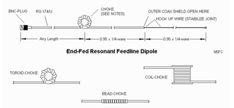 Experiences with the end-fed dipole based on the concepts presented by J. Taylor in an article titled RFD-1 and RFD-2: Resonant Feed-Line Dipoles in QST. August 1991.
 -
 Amateur Radio 40m 20m 15m Half Wave Fan dipole antenna project with part list, pictures and drawing. Includes the option to expand the antenna to cover the 80 meters band
 -
 Maltronix, HF antennas, dipoles and verticals, switching power supply, power distribution, antenna switch
 -
 A page descibing the principles of OCF antennas also known as windom antennas by DJ0IP
 -
 Home made wire dipole on a lenght of 30 meter 98.4 ft by PE1OPM
 -
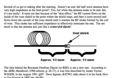 An article on RFD antennas, resonant feed-line antennas
 -
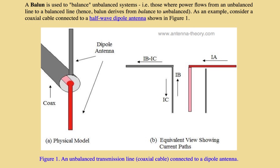 This article describe the principles of baluns when referred to devices used to balance unbalanced systems, like a coax cable and a dipole antenna
 -
 A review of some portable antennas for SOTA operations, including linked dipoles, end-fed, verticals
 -
 The Buddipole Deluxe, a portable HF/VHF antenna system, receives a practical assessment from IW5EDI after a month of field use. The author, constrained by antenna restrictions, highlights the system's crucial role in enabling portable operations, even managing sporadic digital activity from a balcony. Direct comparisons to a fixed 3-band dipole reveal surprisingly comparable signal reports on 15, 17, and 20 meters, underscoring the Buddipole's effectiveness in real-world scenarios. Tuning the Buddipole proves straightforward on bands down to 20 meters, though the review notes significant challenges with SWR on lower bands like 40 meters, where achieving better than 3:1 SWR was problematic. Observations also include SWR variations with dipole rotation and mast height, suggesting environmental factors play a role. The overall manufacturing quality of the antenna and its accessories, including the tripod and carry bag, is deemed good, despite a minor issue with a pole connector. Looking ahead, the author plans to construct a homemade Buddipole version, possibly optimized for the 30-meter band, specifically for PSK31 operations from an apartment. This personal project reflects a common amateur radio practice of adapting commercial designs for specific needs, further extending the utility of portable antenna concepts.
 -
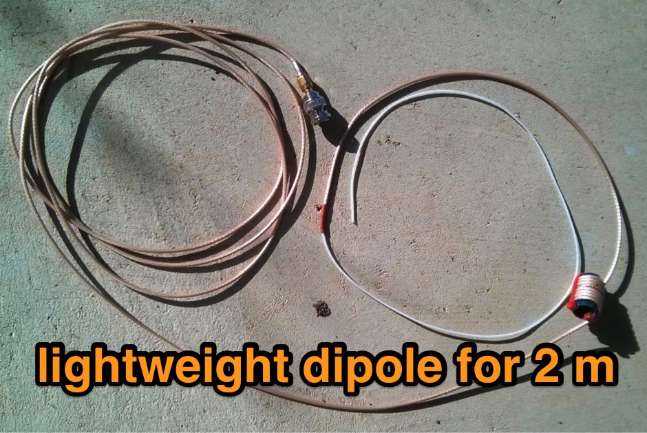
 This article serves as a beginner-friendly guide to constructing a simple VHF dipole antenna for 2 meters, perfect for novices in the hobby. With an emphasis on affordability and simplicity, it explains the basics without overwhelming technical details. Recommendations for coaxial cable and mounting methods are provided, offering practical solutions for effective communication. By following these instructions, novices can build a functional antenna without breaking the bank.
 -
 This handy and cheap portable dipole can be folded and backpacked, carried in use, and adjusted to a very wide range of frequencies.
 -
 About windom antennas and OCF dipoles, tricks on covering more bands moving feed-points and potential problems. Problems caused by common mode currents in OCF dipoles
 -

-
 An easy to build dipole for 21 and 14 MHz with traps made by two T50-6 toroids cores mounted on a simple PCB foil
 -
 A presentation of the Yagi Antennas, and other interesting tid-bits by Brian Mileshosky. The document provides an in-depth exploration of the Yagi-Uda antenna, detailing its historical development, design principles, and performance characteristics. Originally described in the 1920s, the Yagi antenna features a driven element and parasitic elements, including reflectors and directors, which collectively determine its behavior. The document highlights how element lengths, diameters, and spacing influence gain, impedance, and directivity. It also discusses the antenna's reciprocal nature and presents data on typical gain values for various element configurations. Additionally, the text covers practical considerations, such as the construction of a "Tape Measure Yagi" for amateur use, and touches on related antenna types like dipoles and their application in Near Vertical Incident Skywave (NVIS) communication.
 -
 The collinear antenna, or Marconi-Franklin antenna, is an omnidirectional, high-gain antenna composed of in-phase half-wave dipoles aligned vertically. By using quarter-wave transmission line segments, it maximizes gain at a low horizon angle, outperforming a half-wave dipole. Adding segments increases gain but narrows bandwidth. A popular DIY version, the CoCo antenna, uses half-wave coaxial cable segments connected by non-radiating transmission lines. Built with stable velocity factor cables, a matching quarter-wave sleeve balun, and ferrite rings for attenuation, the antenna achieves performance comparable to commercial models.
 -
 Two find dipoles one for 75/40/20 and the other for 20/15. These 2 dipoles are at right angles to each other and the 20/15 dipole is located about 6 feet below the 75/40/20 fan dipole.
 -
 A distributed capacity coaxial dipole antenna. The antenna is very broadbanded with a very flat swr on all band when setup of the antenna is done at the proper lenght and height.
 -
 Operating a ham station often involves encountering radio frequency interference (RFI), RF feedback, or RF burns, which are frequently misattributed to poor equipment grounding. This resource meticulously dissects these assumptions, asserting that RF grounds on the operating desk often merely mask more significant system flaws. It identifies five primary causes for RF problems, including antenna system design flaws, proximity of the antenna to the operating position, DC power supply ground loops, equipment design defects, and poorly installed connectors or defective cables. The content emphasizes that issues like "hot cabinets" or changes in SWR when connecting a ground indicate substantial RF flowing over wiring or cabinets, a phenomenon known as common-mode current. The article provides detailed explanations of common-mode current generation, particularly from single-wire fed antennas like longwires, random wires, and OCF dipoles, which inherently present high levels of RF in the shack. It also illustrates how vertical antennas, lacking a perfect ground system, can excite feed lines with significant common-mode current. Through simulations, the author demonstrates how a dipole without a proper _balun_ can cause RF problems at the operating desk, showing current patterns and voltage distributions on feed line shields. The discussion extends to the proper application of _RF isolators_ and _ferrite beads_, clarifying their role in modifying common-mode impedance on cable shields and cautioning against their use as a band-aid for fundamental system defects. The resource advocates for correcting the actual source of RF problems, such as antenna system issues or poor connector mounting, rather than relying on internal shack grounding or isolators. It highlights that properly functioning two-conductor feed lines, like coaxial or open-wire lines, should result in minimal RF levels at the operating position, even without a desk RF ground. The author shares personal experience, noting that his stations since the late 1970s have operated without RF grounds at the desks, relying instead on proper antenna system design and feed line integrity.
 -
 An interesting presentation of a real multiband Fan Dipole antenna, optimized for better DX operation performances, considering the terrain, position, DX destination path and other influencing factors
 -
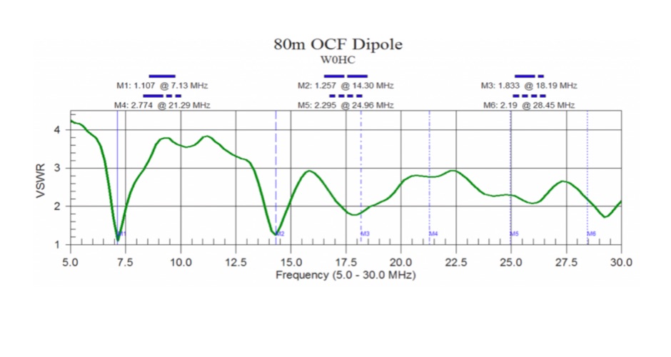
 An easy to build and extremely high performance antenna, works perfectly on all HF bands 3.5-28 MHz with some compromises, it is basically an half wave dipole for 40-80 meters, an LC circuit or trap 40 meters allows you to use a single radiating element.
 -
 US amateur radio antenna manufacturer. Produce baluns, delta loops, dipoles, ocf antennas and more
 -
 Constructing a compact directional antenna for the 17-meter band, this resource details the build process for a Moxon rectangle, a two-element Yagi variant with folded-back elements. It covers the antenna's evolution from the _VK2ABQ beam_ and provides specific dimensions for a version built using fishing pole whips. The content includes a discussion of the antenna's radiation pattern, feedpoint impedance, and its inherent front-to-back ratio, which is often superior to a standard two-element Yagi. Practical considerations for element spacing and material choices are also addressed, alongside a visual representation of the antenna's physical layout. Performance data presented includes a comparison showing the Moxon rectangle's **2.5 dB gain** over a half-wave dipole and a front-to-back ratio of **20 dB**. The resource also touches upon the antenna's relatively wide bandwidth for a two-element beam and its suitability for portable operations due to its compact footprint. It offers insights into optimizing the design for specific operating conditions and discusses the advantages of its lower take-off angle compared to omnidirectional wire antennas, making it effective for DX contacts on the 17-meter band.
 -
 The dipole shown in this document is installed in an inverted Vee configuration, with two leg elements on each side held parallel to each other by 21cm spacers. The upper leg is for 40m and the lower leg for 20m. The spacers are made of 7mm plastic garden hose support for garden sprayers cut to 21cm.
 -
 The 160-meter amateur radio band, spanning 1.8 to 2 MHz, was historically the lowest frequency amateur allocation until the introduction of the 630-meter and 2200-meter bands. ITU Region 1 allocates 1.81–2 MHz, while other regions use 1.8–2 MHz. This band, often called "Top Band" or "Gentleman's Band," was established by the International Radiotelegraph Conference in Washington, D.C., on October 4, 1927, with an initial allocation of 1.715–2 MHz. Effective operation on 160 meters presents significant challenges due to the large antenna sizes required; a quarter-wavelength monopole is over 130 feet, and horizontal dipoles need similar heights. Propagation is typically local during the day, but long-distance contacts are common at night, especially around sunrise and sunset, and during solar minimums. The band experienced a resurgence after the LORAN-A system was phased out in North America in December 1980, leading to the removal of power restrictions.
 -
 T2FD is a 600-900 ohms folded dipole, terminated with resistor. Feed impedance is coupled with 50/600 ohms voltage balun. It is a wide band antenna with rather low SWR over the full designed frequency range: antenna tuner is seldom needed.
 -
 The Superantennas MP-1 portable HF antenna is analyzed for its design and field performance, particularly its high-Q loading coil and 3/8-inch mounting. The review details the antenna's construction, including an 8-inch vertical section, a large-diameter loading coil tuned by a sleeve, and a 4-foot whip that disassembles into six rods for transport. Initial testing with the supplied 10-foot ribbon cable "ground plane" yielded poor SWR and RF hot conditions, indicating an inadequate ground system. Further experimentation with longer radials and resonant counterpoises for each band improved matching and eliminated RF hot issues, but introduced significant operational complexity. The author notes the difficulty in optimizing both counterpoise length and coil setting without an antenna analyzer, and the sensitivity of the MP-1 to counterpoise deployment. The review also discusses the recommendation to tune for maximum received signals rather than minimum SWR, often necessitating an external ATU due to the antenna's typical low impedance. The **MP-1**'s critical dependence on resonant counterpoises for effective operation, especially when elevated, is highlighted as a major drawback for portable use. The author ultimately sold the antenna, concluding that despite its sound technical design, its fussy nature and the need for extensive counterpoise management or an ATU detract from its portability and convenience compared to simpler, less expensive dipole solutions. The **Superantennas MP-1** is deemed a flawed portable antenna, requiring considerable effort to achieve its claimed performance.
 -
 Antennas are influenced by the effect of the ground and by the type of conductors from which they are constructed. Effects of various types of grounds on a 1.825 MHz horizontal 0.5 wave dipole
 -
 A simple drawing schematic of a portable field dipole for 14 MHz with dimensions in meters and instruction for setting up the antenna and to store the radial for easy transportation
 -
 W3HH wide-band wire antenna Article in French. The W3HH antenna, also known as the Terminated Folded Dipole (T2FD), is a compact, broadband antenna for amateur radio. It operates at an angle of 20 to 40 degrees and covers frequencies from 3 to 30 MHz. The antenna features a total length of one-third of the wavelength at its lowest frequency and is fed using a 1:4 BALUN transformer for impedance matching. A termination resistor around 390 Ω optimizes performance, making it suitable for various amateur radio applications while being easy to construct and install.
 -
 This web article details the construction of a 4-meter band coaxial dipole antenna, designed for operation between **70.000 MHz and 70.500 MHz**. The resource provides a bill of materials and step-by-step assembly instructions for a half-wave dipole constructed from _RG-58_ coaxial cable. The design specifies a direct 50 ohm feedpoint impedance, eliminating the need for an external matching network. Construction photographs illustrate the stripping and soldering processes for the coaxial cable elements, ensuring proper electrical connection and physical integrity. The article includes specific dimensions for the radiating elements, derived from calculations for the 70 MHz band. The project outlines the physical dimensions required for resonance at 70 MHz, with the outer braid forming one half and the inner conductor forming the other. The feedline connection is directly to the coaxial dipole's center, maintaining a 50 ohm characteristic impedance. While the article does not present SWR plots or VNA sweeps, it focuses on the mechanical construction and dimensional accuracy for achieving a functional 4-meter dipole. The design is intended for fixed station use, with no specific mention of polarization or height above ground, but implies a standard horizontal orientation for dipole operation. DXZone Focus: Web Article | 4m Coaxial Dipole | Construction Guide | 50 ohm Feed
 -
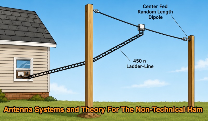 The 60-page PDF document, "Antenna Systems and Theory For The Non-Technical Ham" by Jim Abercrombie, N4JA, provides a foundational understanding of antenna systems. It explains basic antenna theory, including how antennas work, electromagnetic wave polarization, and the role of frequency. The resource details various antenna types such as flat top dipoles, inverted-V dipoles, shortened loaded dipoles, G5RV dipoles, Carolina Windoms, and end-fed configurations. Vertical antennas, including ground-mounted trapped verticals and inverted-L verticals, are also covered. Directional beam antennas like monoband Yagis, cubical quads, and log-periodic arrays are discussed. Propagation modes, including ground-wave, direct wave, and skywave propagation, are explained in detail, with specific attention to the D, E, and F layers of the ionosphere and their effects on HF communication. Technical concepts such as standing wave ratio, decibels, resistance, and reactance are defined, along with calculations for half-wave resonant dipole lengths. The document addresses feed-line radiation, balun applications, and critical antenna and tower safety considerations. It aims to dispel common antenna myths and educate hams on making informed antenna choices.
 -
 This design has the following advantages low-cost components, Easy to set-up - nothing to adjust, no metalwork required, and only four soldered joints!
 -
-
 Documents the construction of a **VHF/UHF** antenna addition for the Buddipole HF antenna system, leveraging the existing Versa-Tee component. The project details the fabrication of a custom antenna mount from angle aluminum, including specific drilling and tapping for 3/16"-24 bolts, and the creation of radials from Simpson Strong Tie Insulation Supports. It specifies radial lengths for 70 centimeters (6 inches from the center stud) and 2 meters (19 1/4 inches), noting the use of wire nuts for safety. The resource outlines the construction of a mast from 1/2" ID PVC conduit, connected with 3/8"-24 connecting nuts and bolts, mirroring the Buddipole's modular design. It describes the integration of a mobile dual-band antenna with a 3/8"-24 mounting stud and the custom coax setup with BNC and **PL-259** connectors. Field testing with an FT-817ND and a separate dual-band SWR meter confirmed good SWR on both 2 meters and the 440-450 MHz section of 70 centimeters, with positive reception reports during Field Day activities. Further, the article describes the creation of a custom carrying solution, including a 22-inch tripod bag and a fabric roll-up, to emulate the portability of the original Buddipole system.
 -
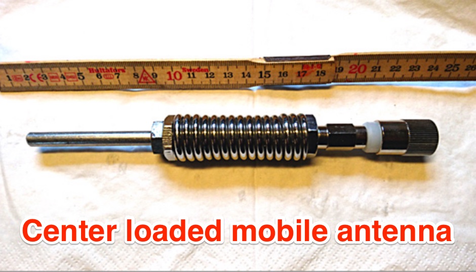 The OZ1CX center-loaded mobile antenna project details the construction of a compact **80-meter** antenna, specifically designed for mobile, portable, and stationary operations. It features a loading coil wound on a 50 mm PVC pipe with 1.5 mm copper wire, comprising 100 turns over 150 mm length, resulting in an inductance of 150 µH. The design incorporates a 1.5-meter whip and a 1.5-meter base section, with the coil positioned at the center for optimal performance on the 3.5 MHz band. Performance measurements indicate a **VSWR** of 1:1.2 at 3.7 MHz when mounted on a vehicle, achieving a bandwidth of 30 kHz for VSWR below 1:2. The antenna's efficiency is compared to a full-size dipole, showing a signal strength reduction of 3-4 S-units, which is typical for compact mobile HF antennas. Practical application notes cover tuning adjustments by varying the whip length and coil tap points, emphasizing the importance of a good ground plane for effective operation.
 -
 The antenna in this project is a modification of the techniques used to design a multiband fan type dipole with little or no tuning involved having a total space of 105 feet
 -
 SWR analysis of an Alpha-Delta DX-LB Plus antenna, configured as an inverted-V with the apex at 40 feet and ends at 15 feet, reveals specific performance characteristics across the HF spectrum. Measurements were conducted using a RigExpert AA54 antenna analyzer, scanning from 0.100 MHz to 54.000 MHz to capture full-range SWR plots. The antenna exhibits notably narrow bandwidths on 80 meters and 160 meters, attributed to its loading coils, necessitating precise tuning for optimal operation within these bands. Conversely, the Alpha-Delta DX-LB Plus demonstrates excellent SWR across the entire 40-meter band, indicating a broad resonance. Performance on 10 meters also shows favorable SWR, though tuning to a desired operating frequency is still recommended for peak efficiency. The article details the methodology and tools employed, building upon a previous "Part 1" analysis of a G5RV antenna, providing a comparative context for antenna evaluation. Practical experience with this multi-band antenna, particularly its loading coil design, highlights the challenges in achieving desired SWR across all bands without specific adjustments. The author's subsequent plans involve replacing the Alpha-Delta DX-LB Plus with a homebrewed 80-40-20-10m parallel **fan-dipole**, aiming for improved resonant characteristics.
 -
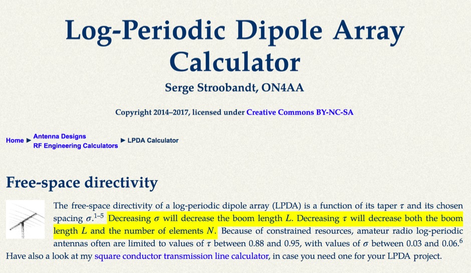 This LPDA calculator is based on the design procedure as described by L. B. Cebik, W4RNL (SK) in the 21st edition of The ARRL Antenna Handbook.
 -
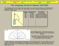 The radiating part is the vertical half of the dipole. You get nearly radiation in all directions, the second half must not be in 180°. The table below show how we get an impedance for direct feeding of 50Ohm coax. by DK7ZB
 -
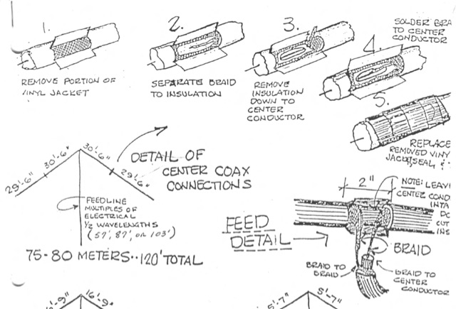
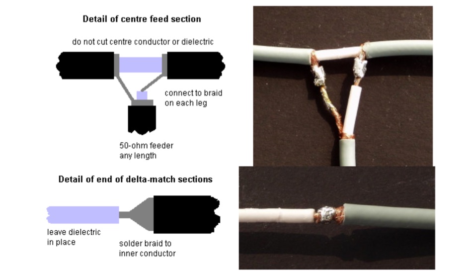
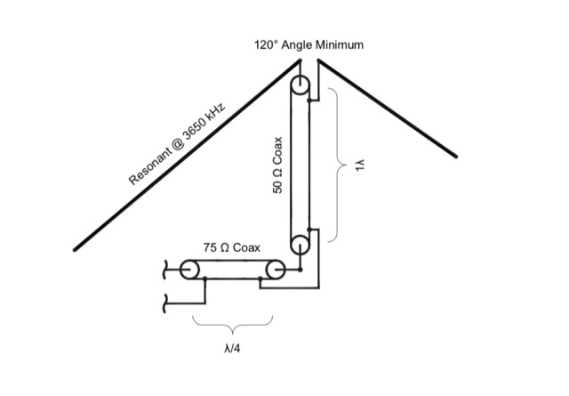 A dipole can be broadbanded by a number of techniques including by matching with resonant sections of transmission feed lines.
 -
 A very popular method of making a short dipoles resonate at a given frequency. This type of antenna is suitable for single band, narrow bandwidth use.
 -
 A simple dipole for 40m band feeded with 450-Ohm openwire feedline includes MMANA Gal files to download
 -
 A simple portable antenna for SOTA VHF is described in this article dedicated to portable operations
 -
 Complete collection of the four main parts of this excellet research on modelling and designing half wave dipole antennas for 40 meters band, covering all aspects beginning from full wave length antennas, to shortened, loaded and reshaped dipoles