Search results
Query: antenna cal.
Links: 1264 | Categories: 63
Categories
- Antennas > 20M > 20 meter Vertical Antennas
- Antennas > 40M > 40 meter Vertical Antennas
- Antennas > Antenna Calculators
- Radio Equipment > HF Vertical Antenna
- Manufacturers > Antennas > VHF UHF Microwave > Vertical Antennas
- Manufacturers > Antennas > HF > Vertical Antennas
- Antennas > 6M > 6 meter J-Pole Antenna
- Antennas > 6M > 6 meter Yagi Antennas
- Software > Antenna analysis
- Antennas > Theory > Antenna Gain
- Shopping and Services > Antennas
- Antennas > Vertical
- Technical Reference
- Antennas > 160M
- Antennas > 17M
- Antennas > 20M
- Antennas > 30M
- Antennas > 40M
- Antennas > 70cm
- Operating Modes > Satellites > AO-51
- Technical Reference > Arduino
- Radio Equipment > Antenna Analyzers > Array Solutions AIM 4170D
- Antennas > Bazooka
- Operating Aids > Beginner's Guides
- Shortwave Radio > Beginner's guides
- Ham Radio > Regional > Brazil
- Radio Equipment > HF Vertical Antenna > Butternut HF2V
- Antennas > C-Pole
- Shopping and Services > CB Radio Stores
- Radio Equipment > HF Vertical Antenna > Cushcraft R5
-
 2 element reversible verticals, small footprint, big results.
 -
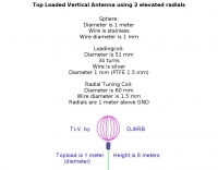 A 3.5 Mhz top loaded vertical antenna built using 2 elevated radials by DJ9RB
 -
 A self supporting vertical antenna for 80 meters by W9OY include pictures and construction details
 -
 Local and DX contacts from tight spaces, it works from 40 to 17 meters
 -
 Multiband and monoband HF Vertical antennas and rotatable dipoles manufacturer based in Texas USA
 -
 Demonstrates the construction of two distinct wideband RF preamplifiers, detailing their component requirements and performance characteristics. The first design leverages monolithic microwave integrated circuits (MMICs) such as the MAR-6, MAR-8, or PGA103, offering a broad frequency response from DC to 2 GHz with a gain of 22.5 dB at 100 MHz and a noise figure typically below 3 dB. This MMIC-based amplifier incorporates protection against power supply transients and features a 50 Ohm input/output impedance, operating from an 8-20 volt supply with low current drain. The second preamplifier design utilizes a BSX-20 transistor, providing amplification across the 14 MHz to 550 MHz range. This simpler, more economical build achieves an average gain of 12 dB at 145 MHz and a noise figure of approximately 1.1 dB. It operates from a 7-15 volt battery supply with a current draw of 6 mA. Both projects emphasize critical construction techniques, such as maintaining short RF connections, ensuring 50 Ohm impedance paths, and mounting the circuit within a shielded enclosure to optimize performance and minimize noise. The resource also discusses phantom power options for antenna-mounted preamplifiers and precautions for use with transceivers, including output protection diodes and static bleeders.
 -
 The half wave dipole antenna is a simple and practical antenna model that consists of a half wavelength long centre fed conductor.
 -
 The QRP choke balun described utilizes a high permeability ferrite rod and RG-174 coax, aiming to present high impedance to common-mode currents across the HF spectrum. The construction involves winding as many turns of RG-174 as possible around the ferrite rod, then encapsulating the assembly with hot glue. This design prioritizes maximizing inductance to suppress unwanted shield currents, particularly in unbalanced antenna configurations. While the balun's effectiveness is subjectively reported as good, a potential design consideration involves the dielectric properties of the hot glue. This material could increase turn-to-turn capacitance, potentially reducing the balun's performance at higher HF frequencies, though this specific aspect has not been formally tested by the author, _AA5TB_. The project serves as an illustrative example of a practical, junk-box construction rather than a rigorously engineered solution. Photographs detail the evolution of the balun, from the initial winding process to its integration within a _B&W dipole center insulator_ and final camouflaged assembly.
 -
 Over **10 million** antennas and flags have been sold worldwide by Firestik Antenna Company, a veteran-owned manufacturer specializing in both CB and amateur radio communication products. Their offerings include a range of antennas, mounting accessories, and coaxial cables, designed for various mobile and fixed applications. The company provides technical support and maintains a network of dealers for product availability. Firestik products are known for their fiberglass construction, which is evident in their _Firestik_ and _Firefly_ antenna lines. The company also produces unique items like the "342 mile per hour Firestik flag," highlighting their diverse manufacturing capabilities beyond just radio antennas. They emphasize their commitment to quality and customer service, including direct technical assistance. The company is located in Tempe, Arizona, and operates under the registered trademark of _Pal International Corporation_. They actively protect their brand, including variations like Firestick and Firestix, ensuring proper representation of their products in the market.
 -
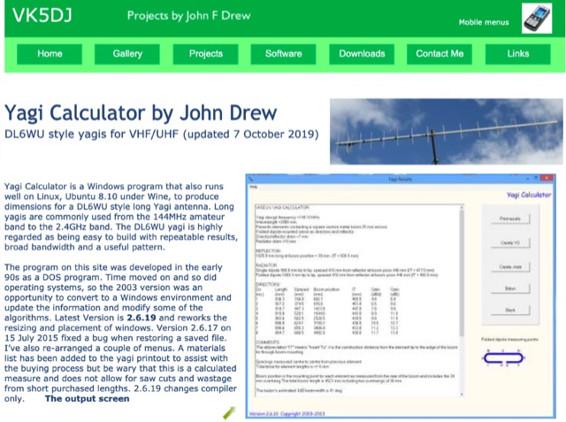 Yagi Calculator is a free Windows program that also runs well on Linux, Ubuntu 8.10 under Wine, to produce dimensions for a DL6WU style long Yagi antenna. Long yagis are commonly used from the 144MHz amateur band to the 2.4GHz band.
 -
 A half-sized Hentenna designed for unique performance in compact spaces. Initially built in 2003 for monitoring a local 146.97 MHz repeater from a basement shop, the antenna proved highly effective, operating at just 200mW. In 2005, it was adapted for use in a challenging river-bottom location, delivering reliable performance on a 2-meter band with 5W. Despite its compact size, the Forktenna demonstrated excellent results compared to a full-sized Hentenna, making it an intriguing option for many hams.
 -
 A 40-meter antenna that provides good local and regional coverage during the day and good DX capability at night
 -
 This note looks at the antenna and antenna model for the 40 meter Moxon Yagi designed by Dave Leeson, W6NL. The performance of the antenna, through the model, will be explored in several typical settings.
 -
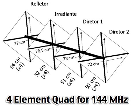 A project for a four element cubical quad antenna for 144 MHz in portuguese
 -
 Radial systems for elevated and ground mounted vertical antennas by SteppIR
 -
 Helical antennas invented by John Kraus give a circular polarized wave. They are one of the easiest to design. Find a tube with a circumference equal to one wavelength, and wrap wire in a helix spaced a quarter wavelengt
 -
 Operating a ZS6BKW antenna often involves understanding its lineage from the _G5RV_ design, with specific modifications by ZS6BKW to optimize performance on several bands. Through computational analysis and field measurements, the antenna's dimensions were refined to allow operation on 10, 12, 17, 20, and 40 meters without an antenna tuner. For 80, 30, and 15 meters, a tuner is necessary, though efficiency on 30 and 15 meters is noted as not particularly high. The physical configuration consists of two 13.755-meter radiating elements fed by a 12.20-meter section of 450-ohm ladder line. Tuning the antenna on the 20-meter band is critical, and any deviation in the ladder line's characteristic impedance necessitates recalculating the element lengths. The design is also referenced in the 12th edition of _Rothammel's Antennenbuch_, page 219. Proper common mode current suppression is crucial at the transition from ladder line to coaxial cable. This can be achieved with a common mode choke, such as several turns of coax wound into a coil or over a ferrite toroid like an Amidon T130. While a 1:1 balun is an option, it may introduce issues.
 -
 40 meter vertical antenna construction, a shortened easy-to-build vertical, with no-radials, made from surplus military camouflage poles
 -
 A vertical antenna specifically designed to work with the 80 meter CW beacon keyer
 -
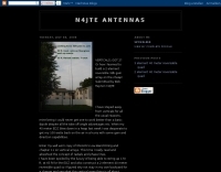
 Sharing information on Topband Homebrew Antennas, Base & Mobile
 -
 A vertical dipole for 10, 15, 20 and 40 meters made adapting two Hustler Model 6-BTV antennas by w6sdo
 -
 A home made vertical polarized moxon antenna for 144 MHz, includes dimensions, antenna pattern, SWR and antenna gain plots by WB5CXC
 -
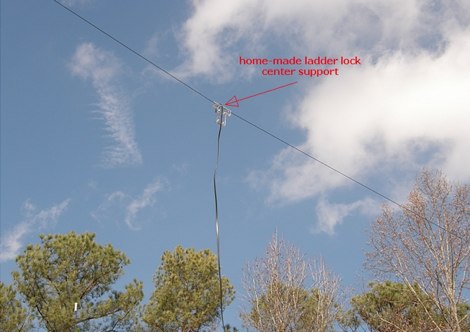
 Yet another G5RV antenna plan to build a G5RV Antenna for 80 to 10 meters usage
 -

-
 A 90-foot vertical antenna constructed from **aluminum irrigation tubing** is detailed, focusing on its innovative raising and lowering mechanism. The resource describes a **45-foot ginpole** system, allowing a single operator to erect or lower the antenna in minutes. It covers the mechanical design, including the pivot base, insulated joints for the tubing sections, and guy wire attachment points. The antenna consists of two 30-foot sections of 4-inch tubing and one 30-foot section of 2-inch tubing, stacked with the smaller diameter at the top. The electrical design incorporates PVC "condulet" boxes at the 30-foot and 60-foot points, housing relays to change the effective height for multi-band operation on 160, 80, 40, and 30 meters. Ferrite rod inductive chokes are used for DC control and to tune out gap capacitance. The antenna is fed with 1000 feet of open wire line, connected to a matching transformer comprising stacked toroids and a coaxial/toroidal balun. Grounding is achieved with a 3x3 foot grid of 16-gauge tinned copper wires with soldered crossovers.
 -
 A marriage of the windom and slinky antennasm, article by NC4TC
 -
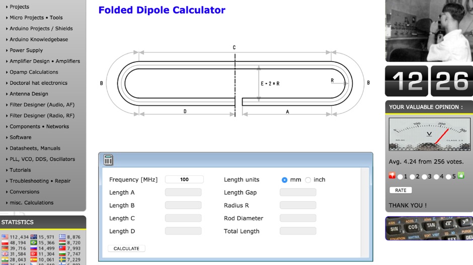 A simple online folded dipole antenna calculator
 -
 A copper pipe Hentenna for 144 MHz. The Hentenna, a compact, high-gain loop antenna developed in Japan in the 1970s, offers approximately 5.1 dBd gain, comparable to a three-element Yagi. Adapted for 2 meters, it is crafted from copper pipe for simplicity, affordability, and broadband performance. Requiring no feed-point tuning, its construction involves soldering standard copper fittings. Installation demands non-conductive materials to minimize signal disruption. Versatile for vertical or horizontal polarization, it is ideal for FM, repeater, SSB, or CW applications. This design emphasizes practicality and performance for amateur radio enthusiasts
 -
 A vertical antenna project than can present low swr from 40 to 10 meters by using a balun in french
 -
 This antenna consists of 4 resonate dipoles made from 12 insulated copper electrical wire. The dipoles are resonate on the following bands: 6 meters, 10 meters, 12 meters and 17 meters.
 -
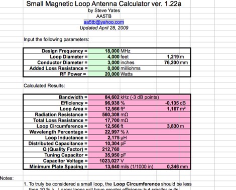 A magnetic loop antenna calculator made with an excel sheet that run also with open office, let you design mag loop antenna dimensions by AA5TB
 -
 Presents a detailed construction guide for a **Quadrifilar Helix Antenna** (QHA) optimized for 137 MHz, specifically for receiving weather satellite transmissions. The resource outlines the author's experience building previous QHA designs, highlighting challenges with tuning and nulls, and then focuses on a refined design by John Boyer, documented by Steve Blackmore, which proved easier to build and yielded superior reception. The guide provides precise element dimensions, including 1.5m of 32mm PVC pipe for the mast and 8mm soft copper tubing for the helix elements. It specifies lengths for horizontal tubes (190mm, 90mm) and helix elements (903mm, 1002mm), along with instructions for drilling, assembly, and forming a **balun** by wrapping RG58 coax around the mast. The text emphasizes critical steps like ensuring elements are square and twisting in the correct direction to avoid phase issues. It includes references to original QST articles by Buck Ruperto (W3KH) and the WxSat program for decoding satellite transmissions, contextualizing the antenna's purpose. The article concludes with a sample NOAA 12 image from September 1998, demonstrating the antenna's reception capabilities.
 -
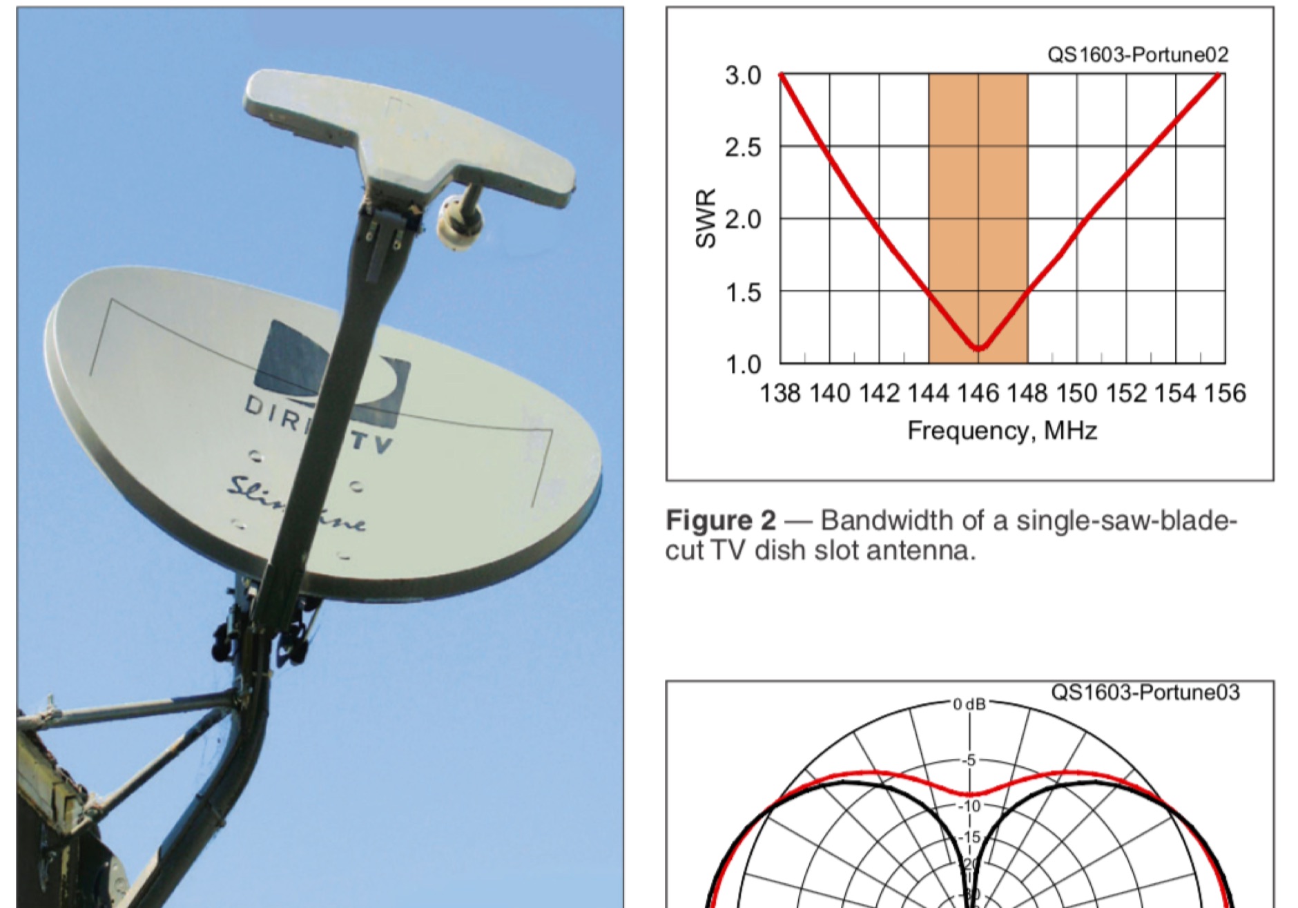 An efficient 2 meter antenna disguised as a TV Satellite dish. This vertically polarized horizontal slot antenna, cut into the reflector of a TV dish, might be the ultimate stealth antenna.
 -
 Calculate Cable Loss from SWR and reverse. Text file with only two simply formulas
 -
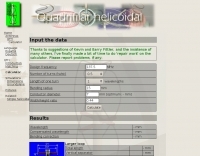 Calculate design for a quadrifilar helicoidal antenna
 -
 This resource details the conversion of an 80m elevated vertical antenna to include 160m operation, focusing on a relay-switched design over a trap-based approach. It presents specific feedpoint impedance values, such as **32 ohms** for 80m and **14 ohms** for 160m, and discusses the challenges of SWR drift encountered with the prior trap system during RTTY contesting. The article thoroughly explains the design choices for elevated radials, referencing _N6LF QEX data_ to debunk common myths regarding radial length and height, demonstrating that non-resonant radials can offer superior current uniformity. The construction section provides practical insights into building the vertical, including guying strategies, material selection from scrap pipe, and weatherproofing the relay assembly. It highlights the use of a common mode choke for the relay switching line, measuring approximately 5K ohms on both 160m and 80m, and details the L/C matching network's role in achieving a 50-ohm match at the end of a 300-foot RG-11 run. The author describes a precise VNA-based radial trimming procedure, achieving resonant values within a 3 KHz range. The content emphasizes the practical application of theoretical antenna principles, particularly concerning the interaction between the vertical element, cap hats, and the matching network. It offers a candid assessment of component selection, such as using junkbox parts and acknowledging the need for future upgrades to static drain resistors. The article serves as a comprehensive case study for advanced antenna builders tackling multi-band vertical designs.
 -
 Demonstrates the design and construction of a 9-element Yagi antenna for the **70 cm band** (432 MHz), based on the DK7ZB concept. The resource details EZNEC+ calculations for a single antenna, providing gain, sidelobe suppression, and front-to-back ratio figures. It also presents a comprehensive analysis of stacking two such antennas, including optimal stacking distance (1000 mm) and the resulting performance enhancements for the stacked array, such as an increased gain of 17.03 dBi. The article includes detailed drawings, wire file dimensions in millimeters, and azimuth/elevation plots for both single and stacked configurations. Practical construction steps are documented with original photographs, illustrating element mounting, the **28 Ohm matching system** using two quarter-wave 75 Ohm transmission lines, and the critical N-connector wiring. It also covers the iterative process of fine-tuning the driven element length to achieve a return loss of 20 dB, validating the EZNEC+ simulation results with actual measurements.
 -
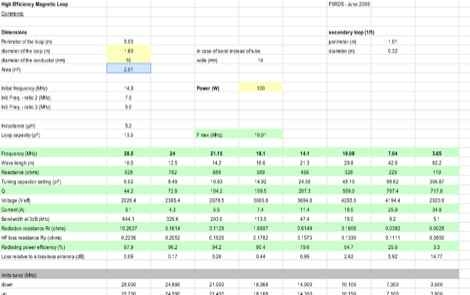 Excel spreadsheet that help calculating dimensions of a high efficiency magnetic loop antenna for HF bands. Giving in input the loop perimeter, loop diameter and loop conductor will calculate electric characteristics, bandwidth, and efficiency
 -
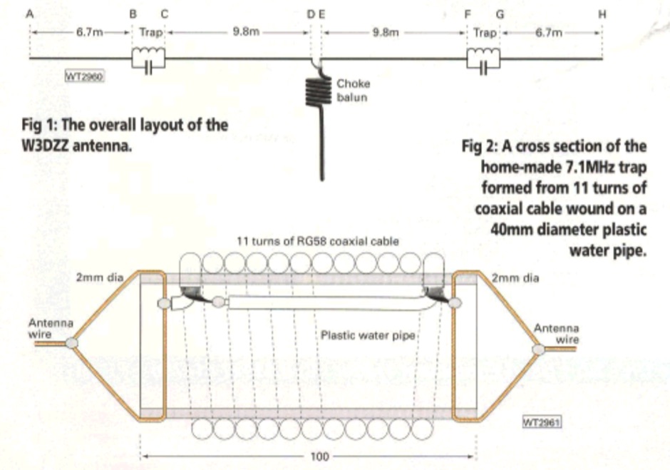 W3DZZ trapped multi-band antenna, exposed in this practical wireless article
 -
 A 2,4 GHz 13cm band quadrible qiad antenna with reflector offering a 14dbd gain
 -
 Cal-av labs, inc. (formerly california avionics laboratories, inc.) manufactures electronic instruments and systems for research and industry. we specialize in radio communications and research/electronic test products. Amateur radio yagi antennas, rotary dipoles, baluns, morse keys.
 -
 A simple quarter-wave length vertical for 40m band using a 12 m spiderpole
 -
 This vertical antenna consist of a 18 meters telescopic pole and allow operations from 160 to 30 meters band, project by Daniel Zimmerman N3OX
 -
-
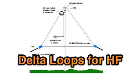 Planning and modelling Delta Loop antennas for all the ham radio HF bands include calculated wire lengths at each mid-band
 -
 The antenna is a vertical dipole, around which four parasitic elements are forming a circle.
 -
 FDLog, a Python-based freeware application, addresses the challenge of synchronized logging for multi-station Field Day operations. It facilitates real-time data sharing across a wireless network, enabling operators to monitor band status and active transmitters at a glance. The software's input system is optimized for minimal keystrokes, streamlining the logging process during intense contest periods. Key features include database synchronization over a wireless network, ensuring all connected computers maintain identical log data. FDLog also incorporates a time synchronization function, designed to keep client programs within a second of a designated master machine, mitigating issues previously encountered with NTP. This internal clock sync can be optionally disabled if not required by the operating setup. Developed initially on Windows 2000, FDLog has demonstrated compatibility with _Linux_ and _macOS_ environments, though some font rendering issues may occur on the latter. The program assists in preparing the ARRL Field Day entry form, simplifying the submission of contest results. User feedback and ARRL rule changes drive ongoing development, with a discussion list available for community support and input.
 -
 One specific challenge in the KazShack, operating Single Operator Two Radios (SO2R), involved sharing a K9AY receive antenna between two transceivers without direct RF connection or manual feedline swapping. The solution, detailed in this project, adapts the **W3LPL RX bandpass filter** design to split 160m and 80m signals, feeding them to separate radio inputs while maintaining isolation. This approach also addresses the issue of strong broadcast band interference from a nearby 50KW WPTF transmitter on 680kc. The construction utilizes T-50-3 toroids and NP0 ceramic capacitors, built in a "dead bug" style on copper clad board. Each band's filter coils are identical and resonated to the desired frequency using an MFJ-259 antenna analyzer. A single DPDT relay, controlled by a remote toggle switch mounted on an aluminum panel, facilitates quick band switching between radios, simplifying low-band operations. While some signal loss is noted, the expected lower noise levels from the receive antenna are anticipated to compensate, potentially reducing the need for constant volume adjustments during toggling between transmit and receive antennas.
 -
 For radio amateurs seeking compact and efficient antenna solutions, particularly for restricted spaces or noise reduction, HF loop antennas present a viable option. This resource compiles several articles from the ARRL, detailing the theory, design considerations, and practical construction of various loop configurations. Topics include small transmitting loops, receiving loops, and multi-band designs, often emphasizing their performance characteristics such as directivity, bandwidth, and impedance matching. The collected articles provide insights into the comparative performance of different loop geometries, such as circular versus square loops, and discuss the impact of conductor size and tuning methods on efficiency. Practical applications are explored, including their use in portable operations, stealth installations, and urban environments where noise mitigation is critical. The content often includes construction diagrams, parts lists, and performance data derived from modeling or field tests, enabling hams to replicate or adapt the designs for their specific operating conditions.
 -
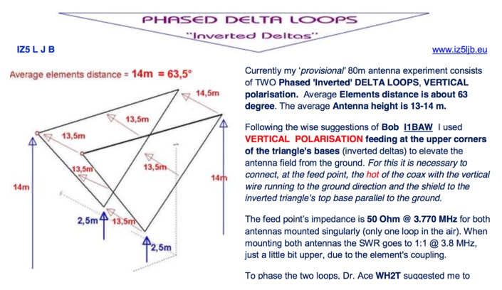 An interesting article with many technical details on a phased delta loop array for 80 meters band includes pictures of antenna relays