Search results
Query: 2m antenna
Links: 183 | Categories: 2
Categories
-
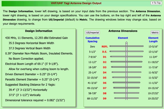 Design your VHF UHF Yagi antenna online, a JavaScript enhanced web page that implements the design of an antenna for 2m and 70cm bands. This page offers a streamlined experience for Yagi antenna design enthusiasts. It assumes prior knowledge of Yagi design principles, minimizing distractions with a user-friendly interface. Equipped with essential equations, it provides instant design feedback. Red font warnings indicate design limitations, ensuring practical results. Constraints include Gain (11.8-21.6 dBd) and Boom Length (2.2-39 wavelengths), with additional frequency-dependent restrictions noted in input fields.
 -
 The G5RV antenna, with an overall length of **31.10m (102ft)**, functions as a 3/2-wave on 20 meters when installed horizontally at 12m (39ft), exhibiting a resonant frequency of 14.150MHz and an approximate resistance of 80 ohms. Its 10.36m (34ft) stub line, designed as a 1/2-wave on 14.150MHz with a 0.97 velocity coefficient, acts as an impedance transformer across other bands, aiming for multiband operation without traps. On 20m and higher frequencies, the G5RV demonstrates improved gain compared to a standard dipole, attributed to the _collinear effect_ from multiple 1/2-waves along the wire. The original design sought a multiband solution for limited spaces, often requiring an Antenna Tuning Unit (ATU) for effective operation across bands like 80, 40, 30, and 20m, particularly with modern solid-state PAs. Variants, such as the F8CI modification, incorporate a 1/4 current balun at the stub line's base for symmetrical-to-asymmetrical transition, known as a _remote balun_. Proper flat-top or inverted-V installation is critical for maintaining symmetry and collinear gain, with inverted-V apex angles below 120° progressively diminishing higher-band performance.
 -
 Details the construction of a **multiband vertical** antenna, specifically designed for stealth operation in a rented property, covering 80m, 60m, 40m, and 30m. The author, N3OX, leverages a 12m Spiderbeam telescoping fiberglass pole as the primary support, noting its sturdiness compared to typical fishing rods while remaining light enough for quick deployment and takedown. The radiating element is a 14 gauge Flex-Weave wire, attached to the pole's top with a rubber grommet, and fed by 27 bare 18 gauge radials spread across a 40-foot square backyard. N3OX describes the impedance matching solution, opting for custom-built L-networks over a remote tuner to enable fast bandswitching. Using an MFJ-259B and EZNEC modeling, base impedances were measured and component values calculated with G4FGQ's L_TUNER and SOLNOID_3 programs. The 80m coil is wound on a 3.5-inch PVC form, while the 30m, 40m, and 60m coils are air-wound, self-supporting #10 wire. Variable capacitors are incorporated for 40m and 30m shunt elements, with the 60m impedance matched by a series inductor. The project includes a **servo-controlled** homebrew band switch, utilizing a two-pole 12-position ceramic wafer switch for remote operation, addressing the limited 80m bandwidth. The entire matching network is housed in a weather-resistant shelter constructed from lumber and aluminum flashing. N3OX reports good DX results at 100W, estimating the total cost between $150 and $250, depending on existing parts.
 -
-
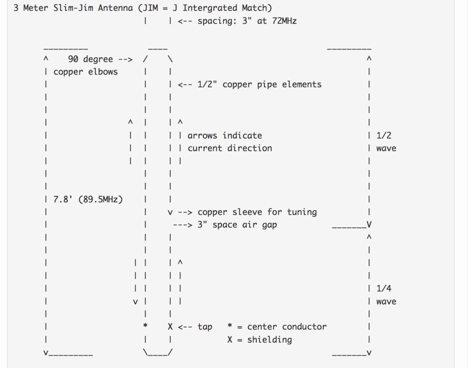
 Constructing a 2-meter 5/4 wave antenna, N1HFX details a design fully enclosed within 3/4-inch PVC tubing, addressing the significant velocity factor of PVC which necessitates a 19% reduction in physical length. The design incorporates a specific matching system using 300-ohm TV twin lead to counteract the highly inductive impedance component inherent in a 5/4 wave radiator. Key components include #18 stranded insulated wire for the radiating element, RG58/U coax, a PL259 connector, and a hardwood dowel for internal support, all carefully dimensioned for optimal performance within the PVC housing. The article provides precise cutting lengths for the twin lead and #18 wire, with the overall assembly measuring 77 3/4 inches, reflecting an approximate velocity factor of 0.81. Tuning instructions emphasize taking SWR readings with the antenna assembly inside the PVC, adjusting the #18 wire and twin lead in small increments to achieve a low SWR across the 2-meter band. The prototype antenna achieved SWR readings below 1.2:1 across the entire band, and N1HFX suggests an estimated 6 dB gain when properly mounted, offering a cost-effective alternative to commercial antennas.
 -
 A 1/4 wavelength resonator design for dual-band VHF/UHF operation is presented, focusing on a robust mobile antenna construction. The design prioritizes stability against environmental influences over raw gain, making it suitable for general use rather than marginal signal areas. It details the antenna's two sections: a UHF-resonant lower conductor and an upper coil functioning as an RF choke for UHF and an inductance enhancer for VHF, forming a resonant circuit. Detailed mechanical structure and material considerations are provided, including the use of a PL-259 plug base, 2mm copper rod, and PVC faucet tube for the coil form. The guide outlines a precise construction procedure, from soldering the copper rod to the PL-259 to winding the 22 SWG laminated wire for the VHF section. Tuning involves careful cutting of the UHF section and adjusting the coil length and pitch for VHF, using a reflectometer and temporary ground planes. Furthermore, the resource describes converting the mobile antenna for base station application by constructing a dual-band ground plane system. This involves using electrical conduit, EMT connectors, SO-239 sockets, and a 4-inch round-pan with threaded stainless steel rods as ground elements. Practical test results indicate optimal lengths of **70mm** for UHF and **350mm** for VHF ground elements, with a recommendation to cut rods with _30mm_ extra length for fine-tuning.
 -
 The Little Stick antenna is an aluminium version of the Vertical Bazooka design which was made from coax.
 -
 A 9 dB gain 70cm collinear antenna construction is detailed, utilizing eight half-wavelength sections of _RG58/U_ coaxial cable. The design incorporates specific calculations for velocity factor (0.66 for RG58/U) to determine precise element lengths, such as 223mm for a half-wavelength at 444 MHz. A quarter-wave radiating element of #16 solid wire, 169mm long, is added to the top, and a 160mm aluminum tube acts as a quarter-wave counterpoise at the feed point. RF choke baluns, constructed from three _FT50-43_ toroids, are positioned a half-wavelength from the feed point to mitigate common mode current. Assembly involves soldering the coax sections in series, followed by SWR testing during construction and final mounting within a ¾-inch PVC pipe. The article suggests using four half-wave elements for a shorter antenna, noting a potential slight increase in SWR, which can be mitigated with quarter-wave ground radials. The design principles and formulas are scalable for other VHF/UHF bands like 6m, 2m, or 1¼m, providing a versatile homebrew solution for enhanced gain.
 -
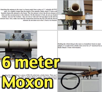 Description and phots of a DIY moxon antenna for six meters band, includes clear pictures, drawings and assembling instruction to build this compact antenna for 50 mhz by N2MH
 -
 Plan of a helix antenna for 2 meter satellite use by VK5ZAI
 -
 The page describes two types of 2 meter J-Pole antennas, one made of copper pipe and a roll-up J-pole made of TV twin lead, providing dimensions, components, and construction details. It is authored by Dr. Carl O. Jelinek N6VNG.
 -
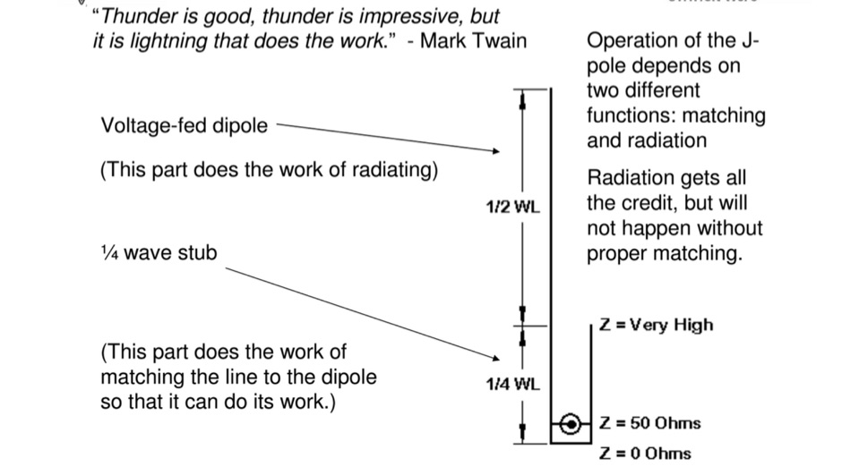 How to Build a Dual-Band Antenna for 2M/70cm presentation PDF file
 -
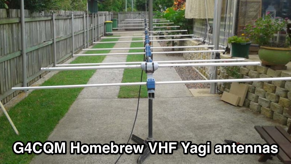 Homebrew VHF Yagi 50MHz 144MHz 432MHz 1296MHz 2320MHz 6M 2M 70CM 23CM 13CM Yagis
 -
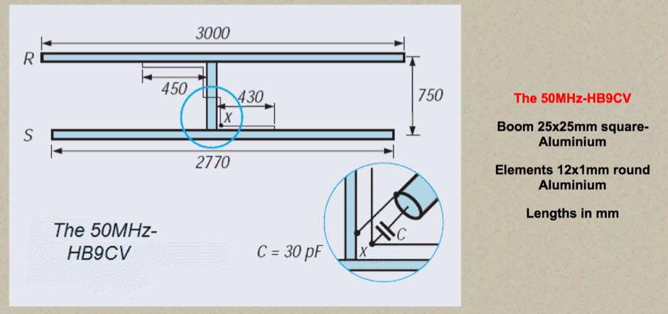 The HB9CV-Beam is a 2-Element-Yagi with two driven elements and was introduced by Rudolf Baumgartner, HB9CV in the 1950ies. This beam antenna is a coax-feeded version of the ZL-Special construction by DK7ZB for 2m, 6m and 10m
 -
 2 meters copper tube antenna, tested with an Icom IC-V8000
 -
 A self-supporting vertical antenna design for stationary-mobile HF-VHF operation is presented, emphasizing ease of construction with common materials like a fiberglass fishing rod and PVC pipe. The design focuses on creating a set of no-tuner monoband radiators for bands such as **2m**, **6m**, 10m, and 12m, with an overall radiator support length of 3.3m. The construction process details the assembly of the antenna base using a magnetic mount, PL-259 connector, and PVC pipe sections, which then supports the telescopic fishing rod. Radiator extensions are cut to achieve quarter-wave resonance on specific bands, with detailed instructions for 6m (50-51 MHz), 10m (28.5 MHz), and 12m (24.9 MHz). For lower HF bands like 15m, 17m, and 20m, the design incorporates base-loading coils, with specific turn counts provided (e.g., 21 turns for 20m). The project also suggests using an _antenna analyzer_ for precise tuning of extensions and coils, moving beyond theoretical values to achieve optimal performance. The author, _IK1ZYW_, notes that for 80m and 160m, the antenna becomes less efficient as a vertical, suggesting alternative configurations like an inverted-V dipole or asymmetrical inverted-L.
 -
 The G3TPW CobWebb antenna design provides a compact, horizontally polarized, omni-directional solution for 20m, 17m, 15m, 12m, and 10m bands. This antenna utilizes five full-size half-wave dipoles, each bent into a square configuration to achieve omni-directional radiation without the nulls typically found in straight dipoles. The design incorporates a single 50-ohm coaxial feedline with an integrated air-core choke balun, minimizing feeder radiation and reducing EMC issues. Construction details include using PVC-covered multi-stranded copper twin cable for elements, supported by a fiberglass cross. The document specifies tapping points for impedance matching to 50 ohms on all five bands, ensuring high radiation efficiency without lossy traps or loading coils. Physical dimensions are compact, with 2.6-meter (8.5 feet) sides and a total weight of 6 kg (14 lbs), making it suitable for mounting on a 20-foot aluminum scaffold pole. Detailed instructions for assembling the junction box, including terminal strip wiring and the coaxial choke balun, are provided with photographs and diagrams. The design emphasizes a confined electric field to reduce coupling to nearby conductors, which helps mitigate TVI and makes the antenna less sensitive to mounting height or ground conductivity.
 -
-
 The Flower Pot Antenna project details a portable dual-band antenna primarily operating on 10 meters, with secondary resonance near the 30-meter band. Construction involves winding RG58 coaxial cable uniformly around a large plastic flower pot, approximately 70cm high with a 60cm top diameter. The design eliminates the need for radials, contributing to its compact and lightweight nature. Key construction steps include soldering the inner conductor to the shield at one end of the wound cable and connecting the wound cable's shield to the rig cable's inner conductor at the base. An LC network, comprising a variable capacitor (0-200pF) and an inductor (10 coils, 5cm diameter, 2mm wire), is inserted between the wound cable's inner conductor and the rig cable's shield. Tuning is performed with an antenna analyzer, adjusting cable length and the variable capacitor for optimal impedance on 10 meters. The antenna performs effectively when installed horizontally.
 -
 Normal mode helix antennas offer a solution for HF mobile operators facing significant height restrictions, such as those parking in indoor garages with limited overhead clearance. This design, adapted from concepts typically applied to VHF/UHF rubber duck antennas, allows for extremely shortened HF radiators that remain effective for county hunting and general mobile operation. The resource details the construction of a 20-meter helix antenna, approximately 10 inches long, wound with #14 AWG THHN wire on a 1 1/2-inch CPVC form, mounted on a standard 3/8 x 24 antenna stud. Mark Herson, _N2MH_, shares his experience developing these antennas, including initial research from the _RSGB VHF UHF Manual_ and practical winding experiments to establish the relationship between turns and resonant frequency. He provides coil data for various frequencies, emphasizing that these measurements were taken with an _MFJ-259a_ antenna analyzer and are dependent on the vehicle's grounding system. Despite their shortened nature, N2MH confirms the antennas' operational effectiveness, citing contacts with KL1V in Alaska on 20 meters and E-skip contacts on 10 meters. The design prioritizes continuous deployment without removal, making it suitable for operators who frequently navigate height-restricted environments.
 -
 A portable antenna for mode B and J satellites
 -
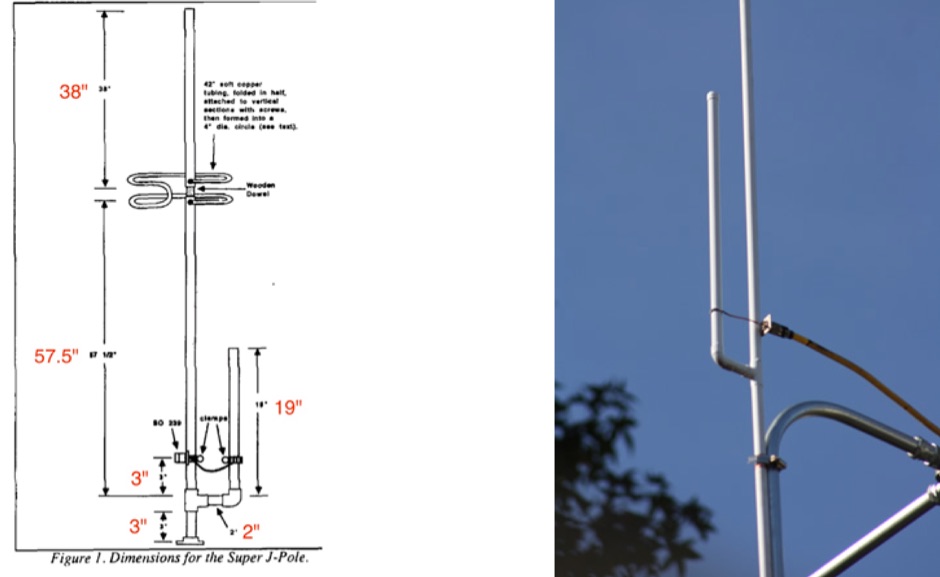 Homebrew a j-pole 2mt and 70 cm antenna project. Make it cheap. This article includes homebrewing instructions, parts lists, tools needed and printable documentation.
 -
 This antenna is intended as a simple, inexpensive solution for the newcomer to experiment across the 40m band (7.0-7.2MHz) when only restricted space is available
 -
-
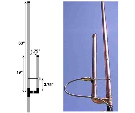 A simple dual band VHF UHF jpole antenna Projects by Dale Kubichek
 -
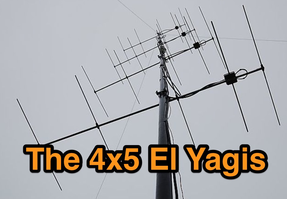 2m SSB/CW-12.5 Ohm Yagis with extrem high gain and small bandwidth. These Yagis were constructed as ultra-light, portable Yagis with extrem high gain. They have small bandwidth and are working from 144,0-144,8MHz with good SWR.
 -
 Demonstrates the construction and performance of an updated ZS6BKW multiband dipole, a variant of the _G5RV_ antenna, specifically designed for HF operation. The article details a real-world installation using 13.5m copper wire elements and 12.2m of 450 Ohm ladder line, configured as a sloping inverted-V with the apex at 10m and ends at 4m above ground. It covers the critical aspect of impedance matching, incorporating an 8-turn choke balun at the feedline transition to RG-58U coax to mitigate RF common mode current. Measurements confirm favorable SWR readings below **1.3:1** on 7.1 MHz, 14.11 MHz, 18.06 MHz, and 24.8 MHz, indicating effective resonance across 40m, 20m, 17m, and 12m bands. The installation also shows usable SWR dips on 3.55 MHz (5:1), 29.02 MHz (2:1), and 50.84 MHz (3:1), extending its utility to 80m, 10m, and 6m with an antenna tuning unit. Initial on-air results report clear reception of stations over **5000km** away, validating its DX potential.
 -
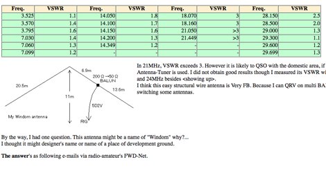 The total length of this antenna is 41m, height is about 11m, and diameter of element is 2mm. JA7KPI modified this antenna originally used as Inverted-V type of 80m band Dipole. Works on 40 - 80 meters band with acceptable swr.
 -
 Suitable antenna for owners of an IC706 or FT817, 857 and other HF portable transceivers. You can an be QRV in a few minutes on all ham-bands from 80m to 6m and even on 2m by PA0FBK
 -
 Drawings of shortened antenna for indoor usage, using short pvc tubes for 2 , 20 and 40 MHz by f1rfm
 -
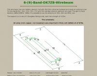 This wire-beam has one radiator-element, feeded with 450-Ohm-Wireman-twinlead and needs an antenna-tuner. For the bands 6m, 10m, 12m, 15m, 17m and 20m bended reflector-elements are used. The support is a cross of 4 fibreglass-fishing-rods
 -
-
 The K5OE 2-meter vertical mobile antenna design, detailed in this resource, employs a 3/8-wavelength vertical section complemented by four shortened radials, forming an off-center-fed vertical dipole. This configuration creates a self-contained lower half, enhancing efficiency compared to traditional 1/4-wave monopoles relying on vehicle bodies for a ground plane. The article specifies construction using PVC components, 10-gauge insulated wire for elements, and provides precise dimensions in both inches and centimeters for the 25-3/16" (64 cm) vertical and 7-3/16" (20 cm) radials. Performance data indicates an honest 3 dBi of gain at 6 feet elevation (2 dBi free-space), with a pattern favoring the horizon, suitable for Low Earth Orbit (LEO) satellite communications. At 20 feet high, the same antenna exhibits almost 6 dBi of gain, with a nominal 50 Ohm feedpoint impedance at 146.850 MHz. Tuning instructions involve trimming element lengths, with the author achieving a 1.2:1 SWR by pruning the mast to 24-3/4" and radials to 7". The resource highlights the antenna's effectiveness for mobile LEO satellite uplinks, particularly at low elevations, and its suitability for fixed, mobile, or portable operations. The flexible wire elements allow for easy folding, making it a practical choice for backpacking. The original design by K5OE was previously hosted on aol.com.
 -
 F6EZX presents a detailed account of constructing a compact, multi-band _Levy antenna_ for portable holiday operations, specifically addressing issues with local QRM from a previous _Deltaloop_ setup. The article outlines the design criteria, including multi-band operation on 40m, 30m, 17m, 15m, 12m, and 10m, a symmetrical configuration to reduce interference, and a low take-off angle for DX. Construction involves 2x 10.3m radiating elements and a 15.3m open-wire feeder (ladder line) with 7cm spacing, made from 1.5mm2 copper wire and foam pipe insulation spacers. Theoretical calculations, referencing F9HJ's "_Les antennes Levy_" book, guide the determination of element lengths and feeder impedance characteristics, aiming for a good match across bands with a commercial antenna tuner. Initial field tests with the _VCI Vectronics VC300DLP_ tuner showed a 1:1 SWR from 80m to 10m, with some difficulty on 17m. The antenna, mounted as a 45-degree slopper with the high point at 12m, successfully facilitated DX contacts to South America, particularly Chile and Argentina, suggesting a lower take-off angle compared to the previous Deltaloop which favored Brazil. The Levy antenna significantly reduced TVI/RFI, attributed to its improved symmetry and greater distance from the QRA. While signal reports on 15m and 20m were 1-2 S-points lower than the Deltaloop, its performance on 40m and 30m was comparable, fulfilling the design goals for a portable, low-cost, multi-band solution.
 -
 Presents G0GSF Brian's ZS6BKW antenna, a refined iteration of the classic G5RV, offering improved performance across multiple HF bands. The design emphasizes specific radiator and ladder line lengths to achieve lower SWR on 40m, 20m, 17m, 12m, and 10m, making it a practical choice for operators seeking a single wire antenna solution. The document includes critical dimensions for the flat-top and the 450-ohm ladder line section, which are key to its multiband resonance characteristics. Unlike the original G5RV, the ZS6BKW aims for direct 50-ohm feedpoint impedance on several bands, reducing the need for an external antenna tuner. My field experience with similar optimized dipoles confirms that precise construction, particularly the ladder line length, is paramount for realizing the intended SWR benefits. This design offers a compelling alternative for hams with limited space or those preferring a less complex antenna system.
 -
-
 Rugged, disguised 2m, 220MHz, 440MHz, and 2m/440 dual band antennas, HF portable antennas, portable dipoles.
 -
 Constructing an HF End-Fed Half-Wave (EFHW) vertical antenna, the resource details the winding of a monoband matching unit, inspired by _AA5TB_, designed to provide a 50 Ohm impedance match without a ground plane or antenna tuner. It specifies the use of a _T200-2_ ferrite core for the transformer, outlining the 13-turn secondary and 2-turn primary winding process with enamelled copper wire. The document also describes the integration of a coax capacitor, whose length is critical for tuning and varies by band, with specific starting lengths provided for 20m, 17m, 15m, 12m, and 10m operation. The practical application section guides the builder through tuning the antenna using an antenna analyzer, emphasizing the iterative process of spacing secondary windings and trimming the coax capacitor to achieve resonance at the desired band frequency. It highlights the antenna's low angle of radiation, beneficial for DX, and claims up to 2 S-points improvement over a _G5RV_ or similar doublet when used as an omnidirectional vertical. A comprehensive shopping list, including specific part numbers from _Rapid Electronics_, is provided, along with advice on selecting fiberglass fishing poles for support and suitable antenna wire.
 -

-
-
 The Buddipole website showcases a range of portable amateur radio antenna systems, including the **Buddipole**, Mini-Buddipole, Buddistick PRO, and BuddiHEX, designed for rapid deployment and multi-band operation from 40 meters to 2 meters. Each product page details specifications, operational modes (dipole or vertical), and compatible accessories like tripods, masts, and baluns. The site also features portable DC power management systems such as the PowerMini 2 and PowerPlus, which include integrated battery chargers and solar controllers, catering to off-grid or field day setups. Instructional videos demonstrate antenna assembly, tuning, and deployment techniques for various configurations, including the VersaTee vertical and Mini-Buddipole. Customer testimonials and DXpedition highlights, such as operations from Montserrat (VP2M) and Dominica (J38), provide real-world examples of the equipment's performance in challenging environments. The company, established in 2001, emphasizes modularity, versatility, and efficiency in its product line, all manufactured in the USA. Shipping information, a 30-day return policy with no restocking fee, and contact details for their Heber City, Utah facility are clearly presented. The site serves as a direct sales portal, offering a comprehensive catalog of antennas, power solutions, and components for portable amateur radio enthusiasts.
 -
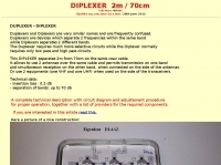 This DIPLEXER separates 2m from 70cm on the same coax cable, and allows to use 2 antennas over the same cable and permits transmission on one band and simultaneous receiption on the other band by hb9abx
 -
 A simple to build Yagi 2 element antenna for 15 or 20 meters band by 9m2mso
 -
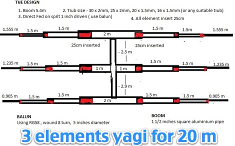 An homebrew project for a 3 elements yagi monoband antenna for the 20 meters by 9M2MSO
 -
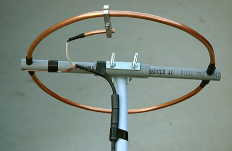 2 Meter Halo Antenna project by Mike Fedler with many detailed pictues and detailes homebrewing instructions so you can build your own
 -
 This technical note explores the application of **Moxon rectangle** antennas for WARC bands, specifically 17 and 12 meters, as compact directional alternatives to standard Yagis. It details three design approaches: a dual-band Moxon using open-sleeve coupling, a Moxon-Yagi combination, and a simplified 1.5 Moxon rectangle. The document provides specific dimensions in feet for aluminum tubing elements (0.75" and 0.5" diameter) for each configuration, along with projected free-space gain, front-to-back ratio, and feedpoint impedance (R+/-jX Ohms) across the respective band segments. Performance tables illustrate gain (dBi), front-to-back ratio (dB), and 50-Ohm VSWR for each design. The dual-band Moxon, despite its compact 7-foot boom, is not recommended due to extreme sensitivity to construction variations, leading to rapidly changing performance characteristics. The Moxon-Yagi combination, featuring a 17-meter Moxon and a 12-meter director-driver Yagi, is presented as a more practical and adjustable solution, offering stable performance with a 10-foot boom. NEC model descriptions are included for simulation in programs like EZNEC, NEC-Win Plus, AO, or NEC4WIN.
 -
 The document details the optimization and construction of the _Maria Maluca_ antenna, a compact 6-band (20m-6m) directional beam. It presents a comparative analysis of shortwave antenna principles, highlighting the efficiency gains achieved by using an open feeder line and tuner as a resonant unit, contrasting this with the losses associated with traps or capacitive loads in multiband antennas. The resource specifically revisits an older South American 2-element design for 10, 15, and 20 meters, applying modern NEC-based software to develop a six-band version. Performance data is meticulously tabulated, showing impedance, free space gain, gain at 12m height, elevation angle, and front-to-back (F/B) ratio for each band from 20m through 6m. For instance, on 15m, the antenna achieves 5.1 dBd free space gain and 13.72 dB F/B ratio. The construction section provides practical guidance on element assembly using aluminum pipes and hose clamps, detailing the use of a heavy-duty glass fiber reinforced polyamide rod for electrical separation and bending strength. It also specifies the use of 450-ohm _Wireman_ line CQ 552 for the transmission line. The document includes diagrams for rod fixing, an air-wound balun, and a vertical elevation diagram for the 15m band, illustrating its DX qualification. It also discusses the antenna's suitability for portable and expedition operations, noting its compact transport dimensions (max 1.50m length, 12 lb weight) and quick assembly time (under 15 minutes). The author, Dipl.Ing. Helmut Oeller, DC6NY, is identified as a source for material kits.
 -
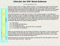 This VHF 145 MHz antenna is easy to build and with no radials. It shows equal gain of 5/8 lambda. It is light weight, you can hang it somewhere (on a tree may be) and work.
 -
 Constructing a compact UHF Moxon antenna for portable radio or TV applications demands a small, easily transportable aerial. This project focuses on a straightforward build method rather than a specific frequency design, leveraging _MoxGen_ software by AC6LA to derive precise dimensions. The author's approach utilizes an epoxy printed circuit board as the support, with traces drawn by a special felt-tip pen for soldering the antenna elements after an etching bath. For high-frequency work, particularly in the GHz range, the choice of insulating material is critical; the article emphasizes the necessity of quality UHF or SHF-grade insulation. A standard SMA connector is integrated, with one element making electrical contact via the nut and the other soldered to the central pin. This ensures a robust feedpoint for the coaxial cable. The coaxial cable, fitted with its connector, is threaded through a 12mm PVC tube that functions as a mini-mast. This tube also defines the antenna's forward direction, which should be aimed at the target signal. A sanitary clamp at the base of the tube secures it to a photographic tripod via its 7mm thread, providing a stable and portable mounting solution.
 -
 The Chameleon V1 HF Multiband Antenna is a mobile antenna that can also be used as portable. Lightweight mil whip antenna system with 10 BANDS capability 6m, 10m, 12m, 15m, 17m, 20m, 30m, 40m, 60m & 80m.