Search results
Query: design a j ple antenna
Links: 216 | Categories: 2
-
 Design your VHF UHF Yagi antenna online, a JavaScript enhanced web page that implements the design of an antenna for 2m and 70cm bands. This page offers a streamlined experience for Yagi antenna design enthusiasts. It assumes prior knowledge of Yagi design principles, minimizing distractions with a user-friendly interface. Equipped with essential equations, it provides instant design feedback. Red font warnings indicate design limitations, ensuring practical results. Constraints include Gain (11.8-21.6 dBd) and Boom Length (2.2-39 wavelengths), with additional frequency-dependent restrictions noted in input fields.
 -
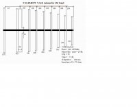
 Demonstrates the construction of a **multi-band HF mobile antenna** utilizing a modified CB whip antenna base. The resource details the process of stripping a commercial CB whip, winding a new helical coil with 0.7mm insulated copper wire, and identifying tapping points for various HF bands. It emphasizes the importance of a rugged, slim design for mobile operation, discussing mechanical length, power handling (up to 200 watts), and coil diameter considerations. The article includes a graphic illustrating the antenna's operational principle, where sections of the helical coil are shorted from bottom to top to maintain efficiency and high Q. The resource presents a practical approach to achieving **band switching** without an external tuner, by manually adjusting tapping points on the coil. It provides a table with reference lengths in centimeters from the feedpoint for 7 MHz (40m) through 28.7 MHz (10m), including WARC bands. The author details mounting techniques, suggesting a Diamond bracket for secure attachment to a vehicle trunk, and stresses the critical role of proper grounding for optimal performance. The design allows for operation on 75m and 80m bands by adding a 110mm steel whip.
 -
 This resource provides a detailed guide on constructing a J-pole antenna specifically for the 2 meter band, which is popular among amateur radio operators. The article outlines the materials needed, including various sizes of aluminum pipes and PVC, as well as the tools required for assembly. It emphasizes the simplicity and effectiveness of the J-pole design, making it an ideal choice for newcomers to amateur radio. The instructions are straightforward, allowing users to build the antenna in less than an hour, and include tips for tuning the antenna for optimal performance. In addition to the construction details, the resource includes practical advice on the assembly process, such as how to cut and join the pipes, as well as how to mount the SO239 connector. The author shares personal experiences and insights on achieving a low standing wave ratio (S.W.R.) and suggests modifications for creating bi-band or tri-band J-pole antennas. This comprehensive guide is enriched with photographs that illustrate the construction steps, making it easier for users to follow along and successfully build their own J-pole antenna.
 -
 The G5RV antenna, with an overall length of **31.10m (102ft)**, functions as a 3/2-wave on 20 meters when installed horizontally at 12m (39ft), exhibiting a resonant frequency of 14.150MHz and an approximate resistance of 80 ohms. Its 10.36m (34ft) stub line, designed as a 1/2-wave on 14.150MHz with a 0.97 velocity coefficient, acts as an impedance transformer across other bands, aiming for multiband operation without traps. On 20m and higher frequencies, the G5RV demonstrates improved gain compared to a standard dipole, attributed to the _collinear effect_ from multiple 1/2-waves along the wire. The original design sought a multiband solution for limited spaces, often requiring an Antenna Tuning Unit (ATU) for effective operation across bands like 80, 40, 30, and 20m, particularly with modern solid-state PAs. Variants, such as the F8CI modification, incorporate a 1/4 current balun at the stub line's base for symmetrical-to-asymmetrical transition, known as a _remote balun_. Proper flat-top or inverted-V installation is critical for maintaining symmetry and collinear gain, with inverted-V apex angles below 120° progressively diminishing higher-band performance.
 -
 This guide provides step-by-step instructions for constructing a tin can waveguide antenna, commonly known as a cantenna, for enhancing WiFi signal range. The project is budget-friendly, costing under $5, and utilizes easily accessible materials like a food can and basic electronic components. The design is suitable for 802.11b and 802.11g wireless networks, operating within the 2.4 GHz frequency range. To start, gather the necessary parts including an N-Female chassis mount connector, nuts, bolts, and a suitable can. The assembly process involves drilling holes in the can for the connector and mounting the probe. The guide emphasizes the importance of can dimensions and placement for optimal performance, encouraging experimentation for best results. This project is ideal for amateur radio operators and DIY enthusiasts looking to improve their wireless connectivity without significant investment. Safety precautions are advised, as the author does not hold electrical engineering credentials. Users are encouraged to take responsibility for their equipment and ensure proper assembly. With this simple yet effective antenna, users can extend their WiFi coverage and enjoy enhanced connectivity.
 -
 An effective 10-20m DX antenna for deed restricted lots. The article by K7ZB introduces a simple 10-20m DX antenna suitable for deed-restricted lots. The antenna, a 15' vertical design, facilitated contacts with over 200 countries worldwide. Its design employs a telescopic aluminum tube and radial wires for multi-band operation, requiring an external antenna tuner for optimal performance. The mounting scheme and construction details ensure effectiveness and ease of use.
 -
 Dissects the internal components of the popular _Antron 99_ vertical antenna, revealing its unique design elements. The analysis details the construction of the coaxial phasing sections, which contribute to its multi-band performance across 10, 12, 15, and 17 meters. Observations include the use of fiberglass tubing for weather protection and the specific arrangement of conductors within the antenna's structure. The examination highlights the antenna's reliance on a series of coaxial stubs to achieve resonance on multiple HF bands without external tuning. This internal architecture provides insights into how the _Antron 99_ manages impedance matching and radiation patterns for effective DX operation. Further details cover the antenna's base mounting and overall physical dimensions.
 -
 A simple design of a 9 elem. yagi antenna for 2 meters band
 -
 Complete guide to build Jpole antennas with online dimensions calculator.
 -
 Demonstrates the construction of **magnetic loop antennas**, detailing both multi-turn and single-turn designs. It covers a 30-inch diameter multi-turn loop for 80 meters, based on a February 1996 QST article, and an octagon single-turn loop made from 15mm copper tube with a 4.8-meter circumference, operating from 7 MHz to 14 MHz. The document also presents a smaller 800mm diameter loop for 14 MHz to 28 MHz, emphasizing the importance of high-voltage tuning capacitors. Covers the design and construction of custom **butterfly capacitors** and piston capacitors, including a split stator capacitor with 140 pF capacitance and a 6000 Volt rating, and a butterfly capacitor with 5-65 pF and 7200 Volt rating. It explains why butterfly capacitors are preferred over split stator types for high power applications due to lower losses and direct series connection of rotors, reducing resistive losses from wiper contacts. Material recommendations include clear PVC for plates and brass or stainless steel for non-magnetic hardware. Addresses practical considerations such as feeding the loop with a shielded 1/5 Faraday loop made from RG213 or RG8 coax, achieving VSWR 1.1 across bands, and optimizing its placement 180° from the capacitor. It also discusses mechanical joint resistance, dissimilar metal oxidation prevention using Vaseline, and a simple method for determining radiation angle with a TL-light tube. The guide includes diagrams for rotor, stator, and end plate construction.
 -
 The **Extended Double Zepp** (EDZ) antenna, a simple wire design, is presented as a means to achieve 3-4 dB of gain on 10 meters, with an overall length of just 43 feet. This resource, authored by WB3HUZ, details several gain antennas suitable for the 29 MHz AM segment, all modeled using EZNEC software at 30 feet above ground. Other designs include a compact rectangular loop, offering more gain than the EDZ and a lower take-off angle, and the **Lazy H**, a bidirectional antenna providing 6 dB gain, which is also workable on 20, 17, 15, and 12 meters. The Bisquare, a diamond-shaped open-top loop, is also featured, providing approximately 4 dB gain and requiring only a single support. These designs are primarily fed with ladder line or open-wire line to simplify matching, though a coax feed option for the EDZ is shown for 10-meter-only operation. The Lazy H, for instance, requires about 16 feet of open-wire line for its half-wavelength elements spaced a half-wavelength apart. An enhanced EDZ Lazy H variant is also discussed, achieving an additional 1-2 dB gain by extending element length to 1.28 wavelengths and increasing spacing to 0.64-0.75 wavelengths. The Bisquare, while primarily a 10-meter antenna, can be adapted for 20 meters by closing the top connection.
 -
 The 144-430 portable j-pole antenna is designed for amateur radio operators seeking a lightweight and efficient solution for VHF and UHF communications. This antenna is particularly useful for portable operations, allowing hams to set up quickly in various locations while maintaining excellent performance. Constructed from readily available materials, it can be easily homebrewed, making it an ideal project for both beginners and experienced operators alike. The j-pole design offers a simple yet effective configuration that provides a good match across the 144 MHz and 430 MHz bands. Its vertical polarization and omnidirectional radiation pattern make it suitable for local communications and simplex operations. This antenna can be deployed in various environments, whether in the field or at home, and is well-suited for mobile applications. With proper construction techniques, operators can achieve optimal performance, enhancing their ability to make contacts during contests or casual QSOs.
 -
 The Pfeiffer Maltese Quad Antenna System presents a unique approach to traditional quad antennas by utilizing a linear loading technique. This method effectively reduces the overall size of the antenna while maintaining its performance capabilities. Designed by Andrew Pfeiffer, the antenna's configuration resembles a Maltese cross, which not only enhances its structural integrity but also allows it to withstand challenging environmental conditions. This system is adaptable, offering various configurations from a 4-spreader Maltese Quad to a 16-spreader Maltese Quadruple-Cross, making it suitable for operators looking to optimize their setup without sacrificing efficiency. This antenna system is particularly versatile, covering multiple bands including 40, 20, 17, 12, and 10 meters. The design focuses on minimizing the physical footprint while ensuring effective signal transmission and reception. Amateur radio operators can benefit from the detailed plans available in the accompanying PDF, which outlines the construction process and specifications. Whether you're a seasoned DXer or a newcomer to the hobby, the Pfeiffer Maltese Quad Antenna System offers a practical solution for enhancing your station's capabilities.
 -
 The page describes a Double-L antenna for 80 and 160 meters bands, designed by Don Toman, K2KQ, with a simple, effective, and ground system-free design. The antenna is a center-fed half-wave vertical with horizontal top and bottom sections, providing good performance without the need for an elaborate ground system.
 -
 The boomless quad antenna is a unique design that offers versatility for amateur radio operators. This antenna consists of two half-wave dipoles arranged in a square or circular shape, allowing for both vertical and horizontal polarization depending on the feed point. The design facilitates easy installation and rotation, making it suitable for various operating conditions. The construction utilizes strong materials, such as bamboo, and incorporates waterproofing techniques to enhance durability. This project outlines the necessary dimensions and materials, including copper wire and insulators, to successfully build the antenna. It emphasizes the importance of tuning each radiator element for optimal performance. The boomless quad is particularly effective across multiple HF bands, including 14 MHz, 21 MHz, and 28 MHz. By following the detailed instructions, operators can achieve a reliable and efficient antenna setup that enhances their DXing and contesting capabilities.
 -
 calculates the dimensions and spacings of the elements needed to build a log periodic antenna, given tao, sigma and the lower and upper cutoff frequencies.
 -
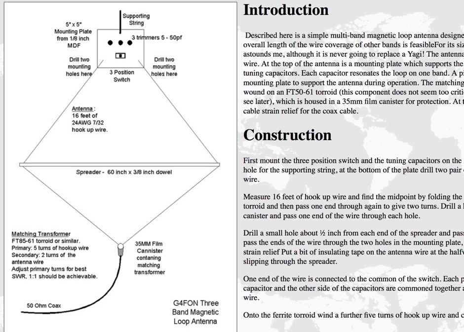 Described here is a simple multi-band magnetic loop antenna designed for 20, 30 and 40 metres, but by changing the overall length of the wire coverage of other bands is feasible
 -
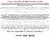 Design your own 5/8 wave vertical antenna. A simple jscript calculator at Antenna Elmer.
 -
 Monitoring shortwave broadcast stations effectively requires accurate schedule information to identify transmissions. This online utility offers a straightforward, graphical interface designed to search for and display current shortwave radio broadcasting schedules. Users can precisely filter results by frequency, specific language, broadcaster, time of day, and even by shortwave band, which simplifies the process of pinpointing desired content. The database, last updated on March 26, 2023, details station callsigns (e.g., BBC), start and end times in UTC, days of the week, broadcast language, transmitter power in kilowatts, and azimuth. Crucially, it includes the precise geographical coordinates of transmitter sites, such as Woofferton in the UK or Al Seela in Oman. This data is invaluable for predicting signal paths and optimizing antenna direction for improved reception, a key consideration for serious SWLs. For instance, a search for BBC English broadcasts at 21:04 GMT quickly reveals multiple active frequencies like 17780 kHz from Woofferton, offering a clear overview of current transmissions. The tool processes queries rapidly, returning results within seconds, demonstrating its efficiency for broadcast listening enthusiasts seeking timely information.
 -
 Determining the actual need for an antenna tuner often hinges on the specific antenna and feed line configuration in use. While many hams believe a tuner is always essential, its primary role is to present a 50-ohm impedance to the transceiver, not to "tune" the antenna itself. For instance, a resonant dipole fed with _coaxial cable_ at its design frequency typically requires no tuner, as the feed line impedance closely matches the radio's output. However, operating a non-resonant antenna, or using a resonant antenna on multiple bands, frequently necessitates a tuner to manage high Standing Wave Ratio (SWR) on the feed line. The article clarifies that a tuner placed at the transceiver only matches the radio to the feed line, not the antenna to the feed line. For maximum efficiency with a non-resonant antenna, an _automatic antenna tuner_ (ATU) or a remote tuner placed at the antenna feed point is often more effective, minimizing losses in the feed line. The discussion also touches on the practical implications of SWR, noting that modern transceivers often fold back power at high SWR, making a tuner a practical necessity to achieve full output power, even if the antenna itself is not perfectly matched.
 -
 The project details a DIY SWR/Wattmeter designed around an _Arduino Uno_ shield, providing capabilities to measure RF power from 2 to **200 watts** and Standing Wave Ratio (SWR) for HF amateur radio bands. This construction features a compact design, integrating the measurement circuitry directly onto a custom PCB that interfaces with the Arduino Uno microcontroller. Key components include a directional coupler for sensing forward and reflected power, precision rectifiers, and analog-to-digital conversion for processing RF signals. The Arduino firmware handles calibration, calculations, and displays the results on an integrated LCD, offering real-time feedback on antenna system performance. The design prioritizes simplicity for homebrewers. Performance specifications indicate accurate readings within the **2-200W** power range, suitable for typical QRP to medium-power HF operations. The project provides schematics and a basic overview of the software logic.
 -
 This Vertical antenna design by David Reid for lower bands focuses on achieving effective DX communication by optimizing the antenna low-angle radiation for long-distance contacts. The design incorporates techniques like linear loading and capacity hats to reduce the antenna's height while maintaining performance, especially on 40m and 80m bands. Building a solid ground plane and using quality materials ensure efficiency and durability. Although vertical antennas can be complex to build, this project simplifies the process, making it accessible for ham operators seeking strong, reliable signals.
 -
 Build your own antenna for the 23cm band ( 1250Mhz - 1280Mc ) using some aluminium and this simple design.
 -
 The 80-meter loop antenna, measuring 86 meters (282 feet) of wire, effectively operates across 8 HF bands from 80 through 10 meters, despite its length being a compromise for specific bands. This design prioritizes a "low enough" SWR across multiple bands, aiming for lower SWR values on higher frequencies due to increased feedline losses. A 200-ohm feedpoint impedance provides a workable SWR on every band, with feedpoint impedances ranging from 100 ohms for lower bands to 300 ohms for higher bands. Radiation patterns for the 80-meter loop, mounted at 15 meters high, show a maximum gain of 7.6 dBi at a 90-degree takeoff angle on 80 meters, and up to 12.9 dBi at a 10-degree takeoff angle on 12 meters. This configuration supports regional contacts on 80 meters and provides good DX performance on higher bands. Practical construction notes emphasize using robust supports like trees, ensuring wire slack with _egg insulators_ for wind resilience, and employing an oversized 2 kW 4:1 _balun_ to safely handle higher SWR conditions, even with 100W transceivers. Feedline losses are minimized using _LMR-400_ coax or ladder line, with power transfer efficiency between 80% and 95%. Antenna simulations were performed using _xnec2c_, and the provided NEC file is compatible with other NEC2 derivatives. The antenna is tunable on 6 of 8 bands with an internal ATU and all 8 bands with an external autotuner like the LDG AT-200 Pro.
 -
 This drawing shows a simple 10 meter wire J-pole antenna designed for 28.4 MHz. It is a vertical, end-fed Zepp-style antenna made from common materials and intended for easy home construction. The main radiating element is a straight length of stranded copper wire, either 14 or 18 gauge, cut to about 16.5 feet. At the top, the wire is supported by an insulator, allowing the antenna to be hoisted vertically. The matching section is made from 450-ohm ladder line, approximately 7 feet 9.5 inches long, and shorted at the bottom. This matching stub transforms the impedance so the antenna can be fed with coaxial cable. The feed point is tapped about 6 inches above the bottom of the stub, with the shield and center conductor connected at the proper points. A choke balun is formed with five turns of RG-58 coax in a 4-inch diameter loop to help reduce unwanted RF on the feed line. The drawing notes that this antenna has about 0 dBd gain, similar to a dipole, but offers an omnidirectional pattern and low-angle radiation when installed high. Its main advantage is practical performance, simple construction, and effective coverage for 10 meter operation.
 -
 Demonstrates the construction and on-air performance of the _NB6Zep_ antenna, a modified 20-meter Extended Double Zepp design optimized for multi-band operation from 40 through 10 meters. The resource covers basic design principles, including dimensions of 66 feet horizontal and 5 feet vertical elements, and specifies open ladder line or TV twin lead for the transmission line. It details material selection for low-cost wire antenna construction, such as 18 AWG wire for the legs and ceramic or plastic insulators, along with practical tips for soldering connections and insulating against moisture. The author, NB6Z, shares insights from extensive _EZNEC_ modeling to optimize the antenna's total length for a 40-meter half-wave dipole footprint and feed line length for direct tuner connection. The article presents field results, including successful _PSK31_ contacts from Oregon to the East Coast on 40 and 30 meters with 50 watts, even at a low height of 6 feet. It provides detailed performance characteristics for each band, noting the _NB6Zep_'s highest gain (over 3 dB) and sharp, medium-angle lobes on 20 meters, which yielded strong DX reports to locations like Korea, Japan, and Argentina. For 17 and 15 meters, it describes a butterfly-like pattern with broad lobes, while 12 and 10 meters exhibit narrow, directional lobes in an "X" configuration. The author also shares personal experiences operating successfully for over a decade in an antenna-restricted environment using the NB6Zep and other stealth wire antennas.
 -
 Catalogs a diverse array of Software Defined Radio (SDR) projects and realizations, systematically classified by their sampling methodologies and underlying hardware architectures. The resource delineates projects into categories such as those utilizing soundcard sampling of traditional transceiver audio outputs (Type Ia), mono soundcard sampling of intermediate frequencies (Type R1x-x-xx), stereo soundcard sampling of I/Q IFs (Type Q1x-x-xx), dedicated stereo audio ADC sampling of I/Q IFs (Type Q2x-x-xx), direct antenna RF signal sampling with off-the-shelf acquisition boards (Type R3x-x-xx), dedicated RF ADC sampling of analog IFs (Type R2x-x-xx), dedicated RF ADC sampling of direct antenna RF signals with ASIC-based processing (Type R4x-A-xx), FPGA-based processing (Type R4x-F-xx), and specialized IF chipsets combining ADC and DDC functions (Type Dxx-S-xx). Each entry provides a brief description, often including pricing, availability of source code, and specific hardware components like ADCs, DACs, DDS, and FPGAs. The compilation presents various practical applications, from PSK31 and Packet radio implementations to adaptations of the DRM standard for amateur radio bandwidths, such as Hamdream and WinDRM. It features specific hardware designs like the SoftRock-40 for the 40-meter band, the Firefly SDR for 30m and 40m, and more complex systems like the Quicksilver QS1R, which employs a 16-bit 130 Msamples/s ADC and an Altera Cyclone III FPGA. The resource also lists sample processing software, RF front-end designs, and academic/commercial SDR initiatives, offering insights into different approaches for I/Q conversion and digital signal processing in SDR systems.
 -
 Multiband Center-Loaded Off-Center-Fed Dipole (CL-OCFD) antenna that work on 80m 40m 30m 20m 15m 10m. The Center-Loaded Off-Center-Fed Dipole (CL-OCFD) antenna, developed by Serge Stroobandt, offers a versatile solution for amateur radio enthusiasts, covering multiple HF bands (80, 40, 30, 20, 15, and 10 meters) without the need for an antenna tuner. This innovative design utilizes a capacitor for resonance on the 80-meter band and a resistor to manage static charges. The CL-OCFD enhances bandwidth and simplifies operation, making it a significant advancement on OCF Dipole design.
 -
 The Inverted L antenna is a versatile and efficient design suitable for small gardens, allowing amateur radio operators to operate on multiple bands. This project outlines the construction of a 5-band inverted L antenna, which can cover HF bands effectively. The design is particularly advantageous for those with limited space, as it requires minimal ground space while providing good performance. The antenna can be easily constructed using common materials, making it accessible for both beginners and experienced hams. In this guide, GM0ONX shares detailed instructions on how to build the inverted L antenna, including dimensions and tuning tips. The project emphasizes the importance of proper installation and grounding to ensure optimal performance. Additionally, it discusses the antenna's compatibility with various transceivers and the potential for portable operation. This resource is ideal for hams looking to enhance their station with a multiband antenna that performs well in limited space.
 -
 One common challenge in antenna systems is mitigating common-mode current on the feedline, which can distort radiation patterns and introduce RF in the shack. This project details a 1:1 balun design that ingeniously avoids traditional ferrite beads, often a costly component, by substituting them with steel wool. The steel wool, when integrated into the balun's construction, effectively attenuates unwanted RF on the outer braid of the coaxial cable, ensuring that the antenna radiates efficiently and as intended. The construction involves winding coaxial cable through a PVC former, with the steel wool strategically placed to provide the necessary common-mode impedance. This method offers a practical and economical alternative for hams looking to build effective baluns without the expense or availability issues associated with ferrite cores. The design principles focus on creating a balanced feed to the antenna, crucial for optimal performance of dipoles and other balanced radiators. Experimentation with such designs can lead to improved field results, particularly for those operating with limited budgets or seeking innovative solutions for their antenna systems. The simplicity of using readily available materials like steel wool makes this a compelling build for many radio amateurs.
 -
 The ZS6BKW multiband HF antenna, a design by ZS6BKW (G0GSF), functions effectively on multiple HF bands without requiring an Antenna Tuning Unit (ATU) for 40, 20, 17, 12, 10, and 6 meters. This antenna, approximately **27.51 meters** (90 feet) long with a 12.2-meter (40-foot) open-wire feeder, is a direct descendant of the _G5RV_ but offers superior multi-band resonance. It can be deployed as a horizontal dipole or an inverted-vee, with the latter requiring only a single support and maintaining an apex angle of at least 90 degrees to prevent signal cancellation. Performance data, recorded with an MFJ Antenna Analyser, indicates SWR values of 1:1 on 7.00 MHz (40m) and 14.06 MHz (20m), with SWR below 1.3:1 on 17m, 10m, and 6m. While primarily designed for these bands, the antenna can be adapted for 80m, 30m, and 15m with an ATU, preferably at the balanced feeder's base. The use of 450-ohm twin-lead for the feeder is recommended over 300-ohm for improved strength and reduced losses, especially in adverse weather conditions. This design, originally published in _RadCom_ in 1993 and featured in Pat Hawker’s "Antenna Topics," provides a compact and efficient solution for HF operation, particularly for those with limited space or resources.
 -
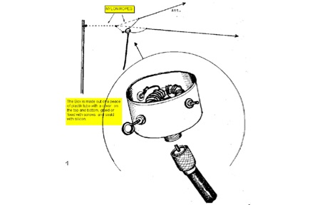
 A simple multi-band magnetic loop antenna designed for 20, 30 and 40 metres, made from 16 feet of RG58 coax cable. The performance is impressive for its size but not meant to replace a Yagi. The antenna features a tuning head, matching unit, tuning capacitors, band change switch, and matching transformer. The feedpoint is at the bottom of the loop. The document provides detailed instructions on assembly and operation.
 -
 A complete documentation with pictures and design of a deltaloop antenna and 1:2.5 balun
 -
 The W3DZZ trap dipole is a versatile and economical antenna option for amateur radio operators looking to work multiple bands without the need for extensive equipment. This antenna design utilizes traps to allow operation on various HF bands, making it suitable for both casual operators and serious DXers. Its construction is straightforward, making it accessible for beginners while still providing excellent performance for seasoned hams. Constructed with readily available materials, the W3DZZ trap dipole can be built to fit specific band requirements, allowing operators to optimize their setup for the frequencies they intend to use. The design is particularly favored for its ability to maintain a low profile while delivering effective radiation patterns. Whether you're contesting or chasing DX, this antenna can enhance your station's capabilities without breaking the bank.
 -
 Presents G0GSF Brian's ZS6BKW antenna, a refined iteration of the classic G5RV, offering improved performance across multiple HF bands. The design emphasizes specific radiator and ladder line lengths to achieve lower SWR on 40m, 20m, 17m, 12m, and 10m, making it a practical choice for operators seeking a single wire antenna solution. The document includes critical dimensions for the flat-top and the 450-ohm ladder line section, which are key to its multiband resonance characteristics. Unlike the original G5RV, the ZS6BKW aims for direct 50-ohm feedpoint impedance on several bands, reducing the need for an external antenna tuner. My field experience with similar optimized dipoles confirms that precise construction, particularly the ladder line length, is paramount for realizing the intended SWR benefits. This design offers a compelling alternative for hams with limited space or those preferring a less complex antenna system.
 -
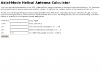 This is my simple implementation of the ARRL Antenna Book design equations for the axial-mode helical antenna.
 -
 End-Fed Half-Wave Antennas (EFHWAs) are analyzed for their utility in portable QRP operations, emphasizing their simplicity, efficiency, and predictable radiation patterns compared to other portable antenna types. The discussion contrasts EFHWAs with vertical antennas, random length wires, and center-fed dipoles, highlighting the common pitfalls of each, such as ground system dependency for verticals and feedline issues for dipoles. The article details the electrical half-wavelength calculation using the formula L (Ft) = 468/F(MHz) and explains how EFHWAs can be resonant on harmonic frequencies, enabling multiband operation. Various deployment configurations are presented, including the inverted L, inverted Vee, sloping wire, and vertical setups, each with specific advantages for radiation angle and polarization. For instance, a vertical EFHWA offers a low angle of radiation suitable for DX contacts without requiring an extensive ground system. The resource also addresses the counterpoise requirements, suggesting a quarter-wavelength wire or connection to a metallic structure for decoupling. A schematic diagram for a simple parallel-tuned circuit tuner, based on the _Rainbow Bridge/Tuner_ design, is provided, detailing component values for 30 and 40 meters, including a 6 microhenry toroidal inductor and a 20-100 picofarad mica compression capacitor. The tuner's adjustment process for SWR matching is also outlined.
 -
 Details a practical QRP wattmeter construction, leveraging a simplified SWR meter design by JA6HIC. The project focuses on a forward-only power measurement circuit, providing a functional instrument for RF power levels from milliwatts up to 5 watts. It maintains a 50-ohm input and output impedance, suitable for typical QRP transceivers and antenna systems. The resource includes the schematic for the "VSW" (Very Simple Wattmeter) and outlines a six-step alignment procedure. This calibration process involves using a known RF source up to 5W, setting full-scale deflection, and marking power increments. It also addresses minimizing frequency effects on readings with a 100pF trimmer capacitor, noting that measurement error is highest at the lower end of the scale. Construction notes mention using a piece of RG-213 coaxial cable for the inductance and coupler, with the wattmeter assembled in early 2003. The author provides an example measurement showing 0.8W into a dummy load and 1W into a 3-element beam.
 -
 The Buddipole website showcases a range of portable amateur radio antenna systems, including the **Buddipole**, Mini-Buddipole, Buddistick PRO, and BuddiHEX, designed for rapid deployment and multi-band operation from 40 meters to 2 meters. Each product page details specifications, operational modes (dipole or vertical), and compatible accessories like tripods, masts, and baluns. The site also features portable DC power management systems such as the PowerMini 2 and PowerPlus, which include integrated battery chargers and solar controllers, catering to off-grid or field day setups. Instructional videos demonstrate antenna assembly, tuning, and deployment techniques for various configurations, including the VersaTee vertical and Mini-Buddipole. Customer testimonials and DXpedition highlights, such as operations from Montserrat (VP2M) and Dominica (J38), provide real-world examples of the equipment's performance in challenging environments. The company, established in 2001, emphasizes modularity, versatility, and efficiency in its product line, all manufactured in the USA. Shipping information, a 30-day return policy with no restocking fee, and contact details for their Heber City, Utah facility are clearly presented. The site serves as a direct sales portal, offering a comprehensive catalog of antennas, power solutions, and components for portable amateur radio enthusiasts.
 -
 5 Band 1/4 wave Telescopic Antenna. The 20m to 10m, antenna is simple and cheap to make, and has a performance that matches commercial antennas but at cost considerably lower. The design was purposely based on a telescoping fibre glass fishing rod as this allows it to be easily stowed away in the car.
 -
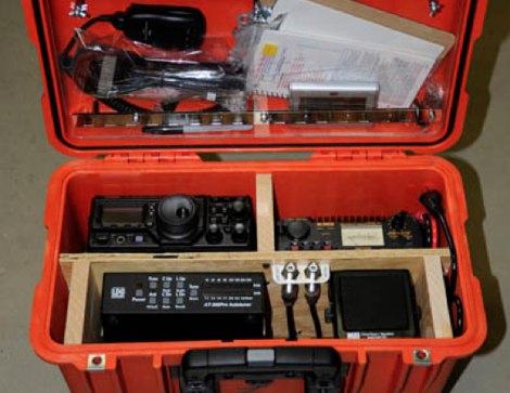 The best way to describe a go-box is a complete amateur radio station in a box. An example is described in this article. The project describes building a portable amateur (ham) radio station, known as a "go-box," housed in a durable orange Pelican case. The go-box contains all necessary radio equipment except for external power and antennae, which are carried separately. It includes items like a Yaesu transceiver, power supply, antenna tuner, speaker, and a clock. The case is designed for mobility and visibility, with a vertical layout to allow in-vehicle operation. Future upgrades might include cooling fans, an LED lamp, and built-in antennae for better functionality in various conditions.
 -
 The K8ZT website provides a curated collection of amateur radio resources, encompassing software tools, informational articles, and external links relevant to various aspects of the hobby. It features utilities for _log analysis_, insights into QRP operations, and guidance on obtaining vanity callsigns. The site also includes sections dedicated to shack design principles and general ham radio information, reflecting a broad interest in practical station setup and operational enhancements. Specific software offerings are presented alongside discussions on their application, such as tools for analyzing contest logs to identify operational efficiencies or areas for improvement. The content often integrates personal experience with technical explanations, providing a practical perspective on topics like antenna selection for low-power operations or optimizing station workflow. The resource distinguishes itself by combining software recommendations with contextual information, aiding operators in making informed decisions about their station's technical and operational aspects.
 -
 Constructing a linear focus parabolic antenna for WiFi operation involves precise metalwork, as detailed in this project. The author, AB9IL, shares a build that can be completed in a few hours, emphasizing the hands-on process of shaping and assembling metal components. This design aims to provide enhanced signal range for 2.4 GHz wireless networks, a common challenge in many ham shacks and home setups. The project outlines the practical steps required, from initial measurements to the final assembly, including cutting, bending, and bolting various metal parts. While specific gain figures are not provided, the parabolic design inherently offers significant _directional gain_ compared to omnidirectional antennas, making it suitable for point-to-point links or extending network coverage over distances. The construction process focuses on readily available materials and basic shop tools, aligning with the DIY spirit prevalent in amateur radio. This antenna project is presented as a straightforward build, requiring attention to detail in fabrication to achieve optimal performance.
 -
 Various tests and designs, with photos of home made EH Antennas,simple and networked, and also sone CAN Antennas.
 -
 The document details the optimization and construction of the _Maria Maluca_ antenna, a compact 6-band (20m-6m) directional beam. It presents a comparative analysis of shortwave antenna principles, highlighting the efficiency gains achieved by using an open feeder line and tuner as a resonant unit, contrasting this with the losses associated with traps or capacitive loads in multiband antennas. The resource specifically revisits an older South American 2-element design for 10, 15, and 20 meters, applying modern NEC-based software to develop a six-band version. Performance data is meticulously tabulated, showing impedance, free space gain, gain at 12m height, elevation angle, and front-to-back (F/B) ratio for each band from 20m through 6m. For instance, on 15m, the antenna achieves 5.1 dBd free space gain and 13.72 dB F/B ratio. The construction section provides practical guidance on element assembly using aluminum pipes and hose clamps, detailing the use of a heavy-duty glass fiber reinforced polyamide rod for electrical separation and bending strength. It also specifies the use of 450-ohm _Wireman_ line CQ 552 for the transmission line. The document includes diagrams for rod fixing, an air-wound balun, and a vertical elevation diagram for the 15m band, illustrating its DX qualification. It also discusses the antenna's suitability for portable and expedition operations, noting its compact transport dimensions (max 1.50m length, 12 lb weight) and quick assembly time (under 15 minutes). The author, Dipl.Ing. Helmut Oeller, DC6NY, is identified as a source for material kits.
 -
 A quarter-wave vertical antenna design for HF operation offers a practical solution for radio amateurs seeking a compact and efficient multi-band radiator. This project details the construction of a 5-band HF vertical, drawing inspiration from established commercial products such as the _DX COMMANDER_ and the MV6. The design emphasizes ease of assembly and disassembly, making it suitable for portable operations or installations with limited space. The article provides insights into various construction methods and offers practical tips for building a robust yet lightweight antenna. It highlights the benefits of a vertical configuration for DX contacts, particularly on the lower HF bands, and discusses real-world performance observations. The antenna is designed to cover multiple HF bands, providing versatility for various operating scenarios. Operators can achieve significant DX results with this type of antenna, often comparable to more complex arrays, especially when deployed with an effective ground system. The project aims to empower hams to build a capable antenna without significant financial outlay.
 -
 Constructing a compact, two-band magnetic loop antenna for HF operation, especially from constrained locations like a balcony, presents unique challenges. OK1FOU's design, inspired by DJ3RW's 50 MHz loop, addresses these by employing an unusual side-fed configuration and placing the symmetric, two-section variable tuning capacitor at the bottom of the loop, directly connected to the coax shield. The article provides specific material recommendations, including two 1-meter wooden pales and about 3 meters of thick loudspeaker cable, noting the high current (60A at 100W) in the loop. Construction steps detail forming two turns with a 5 cm gap, using a GDO to pre-tune the open loop to a frequency slightly above the desired highest band, and then integrating the tuning and coupling capacitors. For 10/14 MHz, an open loop resonance of 16-17 MHz is suggested. Practical experience with the 10 MHz band from a third-floor balcony in Prague (JO70GC) shows a 1:1 SWR across most of the band without an external ATU. While DX traffic was modest due to the urban environment, QSO examples with RA6WF, LA6GIA, G0NXA, and LZ1QK on 10 MHz are provided, demonstrating its operational capability.
 -
 This resource details the computer-optimized design of the _ZS6BKW_ multiband dipole, an evolution of the classic _G5RV_ antenna. It begins by referencing the original 1958 RSGB Bulletin article by Louis Varney G5RV, explaining the operational principles of the G5RV's flat-top and open-wire feedline on 20m and 40m, noting its impedance transformation characteristics for valve amplifiers of that era. The article then transitions to the rationale for optimizing the design for contemporary solid-state transceivers requiring a 50 Ohm match. The core of the project involves using computer modeling to determine optimal lengths for the flat-top and matching section, aiming for a VSWR of less than 2:1 on multiple HF bands. It discusses the process of calculating feedpoint impedance based on antenna length and frequency, referencing professional literature from Professor R.W.P. King at Harvard University. The analysis also considers the characteristic impedance (Z(O)) of the open-wire line, identifying a broad peak of adequate values between 275 and 400 Ohms. Specific design parameters for the improved ZS6BKW are presented, including a shorter flat-top and a longer matching section compared to the original G5RV, with a velocity factor of 0.85 for the 300 Ohm tape. The article confirms acceptable matches on 7, 14, 18, 24, and 28 MHz bands when erected horizontally at 13m, and also discusses performance in an inverted-V configuration, noting frequency shifts. The author, Brian Austin ZS6BKW, emphasizes the antenna's suitability for modern 50 Ohm coaxial cable without a balun.
 -
 This is a simple calculator for solving the antenna wire catenary between to end points given the design wind speed, mass per unit length of the wire, wire diameter and Gross Breaking Strength of the wire.
 -
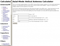 Simple implementation of the ARRL Antenna Book design equations for the axial-mode helical antenna.