Search results
Query: j pole 14 mhz
Links: 53 | Categories: 0
-
 A 2 meter (146 Mhz) J-Pole antenna that is inexpensive, and easy to build.
 -
 The G5RV antenna, with an overall length of **31.10m (102ft)**, functions as a 3/2-wave on 20 meters when installed horizontally at 12m (39ft), exhibiting a resonant frequency of 14.150MHz and an approximate resistance of 80 ohms. Its 10.36m (34ft) stub line, designed as a 1/2-wave on 14.150MHz with a 0.97 velocity coefficient, acts as an impedance transformer across other bands, aiming for multiband operation without traps. On 20m and higher frequencies, the G5RV demonstrates improved gain compared to a standard dipole, attributed to the _collinear effect_ from multiple 1/2-waves along the wire. The original design sought a multiband solution for limited spaces, often requiring an Antenna Tuning Unit (ATU) for effective operation across bands like 80, 40, 30, and 20m, particularly with modern solid-state PAs. Variants, such as the F8CI modification, incorporate a 1/4 current balun at the stub line's base for symmetrical-to-asymmetrical transition, known as a _remote balun_. Proper flat-top or inverted-V installation is critical for maintaining symmetry and collinear gain, with inverted-V apex angles below 120° progressively diminishing higher-band performance.
 -
 The 144-430 portable j-pole antenna is designed for amateur radio operators seeking a lightweight and efficient solution for VHF and UHF communications. This antenna is particularly useful for portable operations, allowing hams to set up quickly in various locations while maintaining excellent performance. Constructed from readily available materials, it can be easily homebrewed, making it an ideal project for both beginners and experienced operators alike. The j-pole design offers a simple yet effective configuration that provides a good match across the 144 MHz and 430 MHz bands. Its vertical polarization and omnidirectional radiation pattern make it suitable for local communications and simplex operations. This antenna can be deployed in various environments, whether in the field or at home, and is well-suited for mobile applications. With proper construction techniques, operators can achieve optimal performance, enhancing their ability to make contacts during contests or casual QSOs.
 -
 The boomless quad antenna is a unique design that offers versatility for amateur radio operators. This antenna consists of two half-wave dipoles arranged in a square or circular shape, allowing for both vertical and horizontal polarization depending on the feed point. The design facilitates easy installation and rotation, making it suitable for various operating conditions. The construction utilizes strong materials, such as bamboo, and incorporates waterproofing techniques to enhance durability. This project outlines the necessary dimensions and materials, including copper wire and insulators, to successfully build the antenna. It emphasizes the importance of tuning each radiator element for optimal performance. The boomless quad is particularly effective across multiple HF bands, including 14 MHz, 21 MHz, and 28 MHz. By following the detailed instructions, operators can achieve a reliable and efficient antenna setup that enhances their DXing and contesting capabilities.
 -
 A simple and cheap dualband j-pole antenna for 144 and 430 MHz
 -
 This drawing shows a simple 10 meter wire J-pole antenna designed for 28.4 MHz. It is a vertical, end-fed Zepp-style antenna made from common materials and intended for easy home construction. The main radiating element is a straight length of stranded copper wire, either 14 or 18 gauge, cut to about 16.5 feet. At the top, the wire is supported by an insulator, allowing the antenna to be hoisted vertically. The matching section is made from 450-ohm ladder line, approximately 7 feet 9.5 inches long, and shorted at the bottom. This matching stub transforms the impedance so the antenna can be fed with coaxial cable. The feed point is tapped about 6 inches above the bottom of the stub, with the shield and center conductor connected at the proper points. A choke balun is formed with five turns of RG-58 coax in a 4-inch diameter loop to help reduce unwanted RF on the feed line. The drawing notes that this antenna has about 0 dBd gain, similar to a dipole, but offers an omnidirectional pattern and low-angle radiation when installed high. Its main advantage is practical performance, simple construction, and effective coverage for 10 meter operation.
 -
 The multi-band trapped dipole is resonant on approx 3.7, 7, 14, 24 7 28.5 Mhz. The overall top length needs to be approximately 32.9 Meters
 -
 Demonstrates the construction and performance of an updated ZS6BKW multiband dipole, a variant of the _G5RV_ antenna, specifically designed for HF operation. The article details a real-world installation using 13.5m copper wire elements and 12.2m of 450 Ohm ladder line, configured as a sloping inverted-V with the apex at 10m and ends at 4m above ground. It covers the critical aspect of impedance matching, incorporating an 8-turn choke balun at the feedline transition to RG-58U coax to mitigate RF common mode current. Measurements confirm favorable SWR readings below **1.3:1** on 7.1 MHz, 14.11 MHz, 18.06 MHz, and 24.8 MHz, indicating effective resonance across 40m, 20m, 17m, and 12m bands. The installation also shows usable SWR dips on 3.55 MHz (5:1), 29.02 MHz (2:1), and 50.84 MHz (3:1), extending its utility to 80m, 10m, and 6m with an antenna tuning unit. Initial on-air results report clear reception of stations over **5000km** away, validating its DX potential.
 -
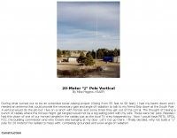 The J pole vertical for 14MHz is built from a fifty-foot TV push up mast by Mike Higgins, K6AER
 -
 Rigid Dipole antennas for 14 MHz band using PVC and Aluminium tubing
 -
 Inverted vee dipole antenna for 20 meters band by VK1OD
 -
 The ZS6BKW multiband HF antenna, a design by ZS6BKW (G0GSF), functions effectively on multiple HF bands without requiring an Antenna Tuning Unit (ATU) for 40, 20, 17, 12, 10, and 6 meters. This antenna, approximately **27.51 meters** (90 feet) long with a 12.2-meter (40-foot) open-wire feeder, is a direct descendant of the _G5RV_ but offers superior multi-band resonance. It can be deployed as a horizontal dipole or an inverted-vee, with the latter requiring only a single support and maintaining an apex angle of at least 90 degrees to prevent signal cancellation. Performance data, recorded with an MFJ Antenna Analyser, indicates SWR values of 1:1 on 7.00 MHz (40m) and 14.06 MHz (20m), with SWR below 1.3:1 on 17m, 10m, and 6m. While primarily designed for these bands, the antenna can be adapted for 80m, 30m, and 15m with an ATU, preferably at the balanced feeder's base. The use of 450-ohm twin-lead for the feeder is recommended over 300-ohm for improved strength and reduced losses, especially in adverse weather conditions. This design, originally published in _RadCom_ in 1993 and featured in Pat Hawker’s "Antenna Topics," provides a compact and efficient solution for HF operation, particularly for those with limited space or resources.
 -
 A rotary trapped-dipole for 17 and 20 meters, as described by IZ7ATH, presents a practical solution for multi-band HF operation. The author, Talino, recounts his experience building this antenna for IK7ZCQ, detailing the evolution from an initial concept involving a grounded-driven element and gamma-match to a direct-fed, non-grounded design. His pragmatic approach, adapting available materials, is evident throughout the construction narrative, particularly with the use of eight tapered aluminum pipes for the driven element. Construction specifics include precise measurements for the aluminum tubing, with diameters ranging from 30 mm down to 16 mm, and a critical note on reducing tip thickness for weight optimization. The _traps_, initially a concern, are fabricated using 8 turns of RG58 coax on a 27 mm support, tuned to resonate at 18.1 MHz using a dip-meter. Talino emphasizes sealing the traps with RF glue and PVC tape to prevent water ingress, a crucial step for longevity. Field test results, conducted on a 10-meter pole in a clear garden environment, showed an SWR of 1.2:1 on 17 meters and 1.5:1 at 14.200 MHz. While SWR varied slightly when installed at Mario's QTH due to nearby objects, the antenna's performance remained commendable. The final half-dipole length is 46 cm for the 18 MHz tips, and the total weight is under 6 kg, with potential for further reduction.
 -
 20 meter wire j-pole for 14.2 MHz, a vertical, end-fed half wave antenna by N1LO
 -
 A double dipole for the 20 and 15 meters band in french
 -
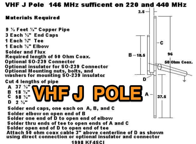 KF4SCI picture of a project for a VHF UHF jpole antenna working on 220 and 440 MHz.
 -
-
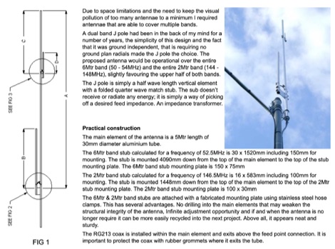 Dual band J pole operational over the entire 6Mtr band (50 - 54MHz) and the entire 2Mtr band (144 - 148MHz), slightly favouring the upper half of both bands by VK6YSF
 -
 This PDF document, authored by KT4QW in October 2004, details the construction and modeling of a dual-band, horizontally polarized hanging rectangular loop antenna for **10 and 17 meters**. The design, adapted from *The ARRL Handbook*, utilizes _NEC4WIN95_ software for scaling and optimization, targeting a 50 ohm feedpoint impedance. The resource includes a bill of materials, step-by-step construction instructions, and a discussion of the antenna's radiation characteristics. It presents NEC-generated elevation and azimuth patterns, comparing the loop's performance to a half-wave horizontal dipole at the same height and frequency. The 17-meter element is centered at 18.140 MHz for low SWR across the phone band, while the 10-meter element is centered at 28.500 MHz. Construction involves 14-gauge stranded copper wire and Schedule 40 PVC spreaders, with the total wire length calculated by the formula: Length in feet = 1005/MHz. The feedpoint impedance can be adjusted by modifying the rectangular aspect ratio. The document specifies hoisting the antenna to at least a half-wave above ground for testing. It notes that a balun was tested and found to have no measurable effect on SWR or radiation characteristics. A 2-meter scale model is presented to illustrate the physical design, and a "rotator" string is incorporated for directional adjustment up to 90 degrees.
 -
 A base station antenna you can easily build for 146,220 or 440 MHz, with performance similar to a J-pole but smaller and less obstrusive
 -
 A 144 MHz dipole antenna made from coax, PVC pipe, and aluminum foil tape
 -
 An homebrewed dipole antenna for 14MHz
 -
 JJ0DRC's HF multi-band delta loop antenna project, initially conceived during the waning peak of Cycle 23, addresses the common challenge of achieving effective DX operation from a small residential lot in Japan. Dissatisfied with a ground plane antenna's performance in SSB pile-ups, the author sought a beam-like solution without a tower, drawing inspiration from a JJ1VKL article in CQ Ham Radio Sep. 2000. The antenna, constructed in October 2000, employs two 7.2-meter fishing rods (37% carbon fiber, reinforced with cyano-acrylate glue and aluminum tape) and 1mm enameled wire, fed by an Icom AH-4 external antenna tuner. While the exact beam pattern remains unmeasured, JJ0DRC observed a significantly higher callback rate compared to dipole antennas, particularly on higher bands. The system's circumference length of 15-20m is crucial for maintaining a good beam pattern across HF bands, though performance on lower bands like 80m, 40m, and 30m becomes less directional as the length deviates from a full wavelength. Ongoing maintenance addressed degradation issues, including aluminum tape cracking and wire breakage at connection points due to strong winds (often exceeding 10-15m/s in winter). The author reinforced rod connections with IRECTOR PIPE SYSTEM components and INSU-ROCK ties, and improved wire attachment methods using Cremona rope and epoxy bond to enhance durability.
 -
 This resource details the computer-optimized design of the _ZS6BKW_ multiband dipole, an evolution of the classic _G5RV_ antenna. It begins by referencing the original 1958 RSGB Bulletin article by Louis Varney G5RV, explaining the operational principles of the G5RV's flat-top and open-wire feedline on 20m and 40m, noting its impedance transformation characteristics for valve amplifiers of that era. The article then transitions to the rationale for optimizing the design for contemporary solid-state transceivers requiring a 50 Ohm match. The core of the project involves using computer modeling to determine optimal lengths for the flat-top and matching section, aiming for a VSWR of less than 2:1 on multiple HF bands. It discusses the process of calculating feedpoint impedance based on antenna length and frequency, referencing professional literature from Professor R.W.P. King at Harvard University. The analysis also considers the characteristic impedance (Z(O)) of the open-wire line, identifying a broad peak of adequate values between 275 and 400 Ohms. Specific design parameters for the improved ZS6BKW are presented, including a shorter flat-top and a longer matching section compared to the original G5RV, with a velocity factor of 0.85 for the 300 Ohm tape. The article confirms acceptable matches on 7, 14, 18, 24, and 28 MHz bands when erected horizontally at 13m, and also discusses performance in an inverted-V configuration, noting frequency shifts. The author, Brian Austin ZS6BKW, emphasizes the antenna's suitability for modern 50 Ohm coaxial cable without a balun.
 -
-
 This strange looking antenna is a combination of Coupled-Resonator principle by K9AY and a quarter stubs to achieve low angle radiation pattern. Designed with 4nec2 NEC based antenna modeler and optimizer for 145/220/440MHz bands
 -
 The ZS6BKW antenna, a popular multiband wire antenna, offers improved band matching compared to the traditional G5RV. This construction guide details the process, beginning with specific dimensions: 13.11 meters (43 feet) for the 450-ohm ladder line and initial dipole arm lengths of approximately 14.8 meters each. It emphasizes the critical role of an _antenna analyzer_ for accurate tuning, particularly for determining the velocity factor of the ladder line and achieving a 1:1 impedance match. The article outlines the materials required, including a 1:1 current balun, 450-ohm window line, wire for the dipole arms, and a 50-ohm non-inductive resistor for testing. It provides a step-by-step procedure for cutting the ladder line to its electrical half-wavelength, explaining how to calculate the velocity factor using measured and free-space frequencies. For instance, a measured 50-ohm impedance at 12.54 MHz with a calculated free-space half-wavelength frequency of 11.44 MHz yields a velocity factor of 0.91. Final adjustments involve hoisting the antenna to its operational height and fine-tuning the dipole arm lengths to achieve optimal SWR, specifically targeting 14.200 MHz. The _ZS6BKW_ design is noted for its performance on 80m, 40m, 20m, 10m, and 6m, though it is not optimized for 15m operation. The author, _VK4MDX_, shares practical tips for durable construction using stainless steel wire and cable clamps.
 -
 Demonstrates the design and construction of a compact, portable multi-band mini-delta loop antenna, specifically optimized for /P (portable) operations from remote locations like Scottish islands. The resource covers the theoretical underpinnings of half-wave loops, contrasting closed and open configurations, and then details the application of a folded dipole principle to achieve a 50-ohm match for direct coax feed. It presents empirical formulas for calculating element lengths, considering the velocity factor of common wire types, and provides a detailed example for a 20m (14.175 MHz) version. The article includes a comprehensive table of dimensions and allowances for a five-band (20m, 17m, 15m, 12m, 10m) mini-delta beam, along with construction hints for the central support and balun. It specifies a 1:1 trifilar balun wound on a ferrite rod and describes the antenna adjustment process using an _MFJ-259B Antenna Analyser_. Initial test results indicate an SWR of 1:1 at resonance and a bandwidth of approximately 240 kHz on 20m, even at a low height of five feet above ground. The distinctive utility lies in its focus on a practical, easily deployable beam antenna for portable DXing, offering a viable alternative to more complex or larger arrays.
 -
 Homebrew a cobwebb antenna for the HF bands. This page describe a cobwebb multiband antenna resonating on 14 18 21 24 and 28 MHz. The cobweb antenna model can be considered a fan dipole, or better, multiple dipoles fed in parallel.
 -
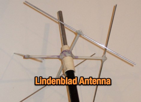 A Lindenblad Antenna for 145 MHz and 435 MHz with an integrated 50 MHz J-pole
 -
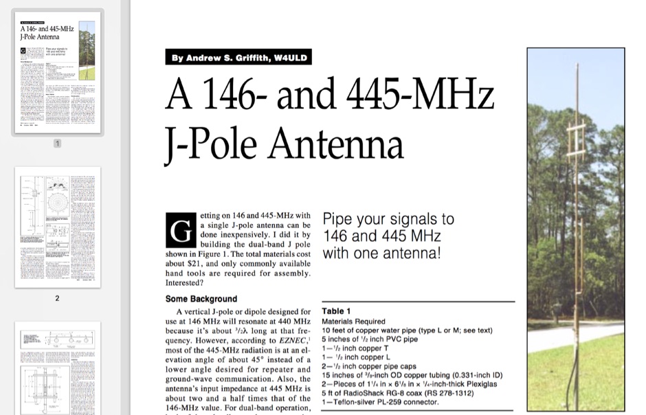 Pipe your signals to 146 and 445 MHz with one antenna!
 -
 The G5RV multiband HF antenna, designed by Louis Varney (G5RV) in 1946, is a popular compromise antenna offering good overall performance on most HF bands when paired with an external antenna tuner. The basic full-size G5RV measures 102 feet across the top for 80 through 10 meter operation and is fed at the center via a 34-foot low-loss feed-stub. This interaction between the radiating section and the feed-stub facilitates matching across 80-10 meters with a standard tuner, often eliminating the need for ladder line directly to the shack. The antenna's design center frequency is 14.150 MHz, configured as a 3/2-wave dipole on 20 meters, with its 102-foot length derived from long-wire antenna formulas. Construction details emphasize the matching section, which can be open wire, ladder line (window-type), or TV twin lead. Each type has a specific velocity factor (VF) affecting its physical length for an electrical half-wave on 14 MHz; for instance, open wire requires 33.7 feet (VF 0.97), ladder line 31.3 feet (VF 0.90), and TV twin lead 28.5 feet (VF 0.82). The article provides formulas for calculating these lengths and discusses the antenna's behavior on individual bands, from 3.5 MHz where it acts as a shortened dipole, to 28 MHz where it functions as two three-half-wave long-wire antennas fed in-phase. Practical construction notes include recommendations for vertical descent of the matching section, sealing the coax junction, providing strain relief, and winding a coaxial choke coil to mitigate common mode current. The resource also presents dimensions for double-size (204 ft) and half-size (51 ft) G5RV versions, along with their corresponding matching section lengths for various line types, making it a versatile reference for hams considering this classic wire antenna.
 -
 An home made vertical dipole antenna made with simple material. The antenna has a total length of aproximately 16 feet. In this article appeared on June QST 2019, the author explain how he reached the optimal confirugation changing and adjusting the lower part of the antenna, trimming and spacing correctly the copper wire. PDF File to downloas
 -
-
 The _Italian VHF Beacons_ resource provides a detailed listing of active and QRT amateur radio beacons operating across VHF, UHF, and SHF bands within Italy. Each entry specifies the beacon's callsign (e.g., IQ1SP/B), operating frequency (e.g., 144.411 MHz), QTH locator (e.g., JN44VC), effective radiated power (ERP) in watts, and antenna configuration (e.g., Big Wheel, 4x Dipole, Yagi). This data is crucial for radio amateurs involved in propagation studies, equipment testing, and long-distance (DX) communication on these higher frequency bands, offering fixed signal sources for monitoring. This compilation, last updated in October 2005, serves as a historical snapshot of Italian beacon activity. For instance, it lists several 144 MHz beacons with ERPs ranging from **0.1W** to **10W**, and higher frequency beacons such as I8EMG/B on 1296.880 MHz and I3EME/B on 24192.132 MHz. The inclusion of QRT (Quiet Radio Teletype) status for many entries indicates the dynamic nature of beacon operations over time. Users can utilize this information to identify potential signal sources for band openings or to calibrate their receiving equipment against known transmissions.
 -
 The resource details the construction of a multiband trap-style Inverted-V antenna designed for operation on 3.5 MHz, 7 MHz, 14 MHz, 21 MHz, and 28 MHz. It presents specific winding data for the traps, including the number of turns, wire gauge, and coil former dimensions, crucial for achieving resonance on the target bands. The document provides a parts list and a diagram illustrating the antenna's physical layout and trap placement. It outlines the process for building the traps using PVC pipe formers and specifies the required capacitor values for each trap. The design emphasizes a practical approach to achieving multiband operation with a single feedline, a common goal for HF operators with limited space. The document includes a table with antenna segment lengths for each band, allowing for precise replication of the design. It also offers insights into tuning and adjustment, ensuring the antenna performs optimally across the designated amateur radio bands.
 -
 An easy to build dipole for 21 and 14 MHz with traps made by two T50-6 toroids cores mounted on a simple PCB foil
 -
 A simple drawing schematic of a portable field dipole for 14 MHz with dimensions in meters and instruction for setting up the antenna and to store the radial for easy transportation
 -
 A moxon antenna for the 50 MHz build with 19 feet of 14 AWG copper wire, and based on a set of PVC pipes. This is an easy to build project that will give you an efficient directional antenna on 6 meters band with low SWR on more than 1 MHz bandwidth.
 -
 A multiband Fan Dipole that works on 40 20 15 meters band, making a folded dipole for 7 MHz band and additional element for the 21 MHz and 14 MHz
 -
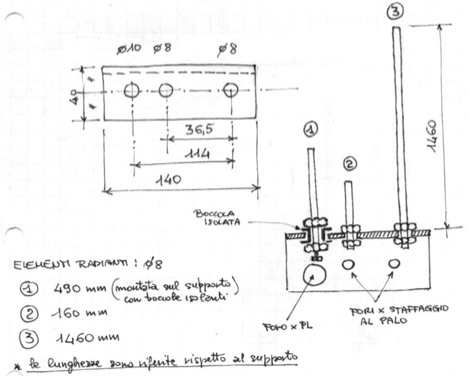 A multiband J-Pole antenna project that cover 144,220 and 430 MHz. The articles includes several pictures of this multi-band antenna, including handmade schematics and diagrams, project is mainly in Italian
 -
 Constructing a high-performance RF spectrum analyzer up to 1000 MHz requires careful attention to component selection, shielding, and circuit isolation. This resource details a project that improves upon the _Spectrum Analyzer for the Radio Amateur_ design by Wes Hayward (W7ZOI) and Terry White (K7TAU), incorporating ideas from Scotty Sprowls' project, particularly his 1013.3 MHz IF bandpass cavity filter. The analyzer utilizes a Mini-Circuits SRA-11 mixer with a sweeping local oscillator from 1013 to 2013 MHz, feeding into a 4-pole copper pipe cavity filter. The design employs a second SRA-11 mixer with a fixed 1024 MHz LO to produce a 10.7 MHz final IF. This signal then passes through narrowband resolution filters and is processed by Analog Devices AD603 and AD8307 ICs for IF amplification and logarithmic detection, driving an oscilloscope in X/Y mode. The project emphasizes modular construction, using salvaged components and double-sided FR4 material for PCBs, with critical notes on minimizing spurious images through effective shielding and proper voltage regulation for each module. Key components include a Z-Communications V585ME48 VCO for the first LO and a Z-Comm V583ME01 VCO controlled by a Motorola MC145151 PLL for the second LO. An optional Hittite HMC307 step attenuator and K&L 5L121-1000/T5000-O/O low-pass filter manage RF input. Tuning procedures for the 10.7 MHz IF resolution filter are also detailed, showing before-and-after spectrum views.
 -
 This DIY vertical multi-band Windom antenna offers a practical and effective solution for amateur radio enthusiasts seeking a versatile and compact antenna for HF communications. Its simplicity of construction, multi-band capability, and favorable performance make it a valuable addition to any radio shack. The article provides detailed instructions on constructing the antenna and balun, along with diagrams and component specifications. Field tests demonstrated successful contacts with stations across Europe and North America on 14, 18, and 28 MHz. The antenna exhibited comparable performance to a W3DZZ dipole and outperformed a Cobweb antenna on 18 MHz. Low noise levels were observed, effectively suppressing background noise.
 -
 A fand dipole antenna home made for the 7,14,50 MHz. This article descbribes how to homebrew the antenna, hot to setup and some SWR measurements.
 -
 This antenna is a classical antenna working on 7,10,14,18,50 MHz is implemented with three traps for 30, 17 and 6 meters
 -
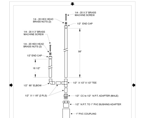 Complete plan for making a 2-meter J-Pole antenna. This drawing in PDF File includes a detailed list of the parts needed to assemble the Jpole antenna for 144 MHz.
 -
 The CobWebb antenna project is a compact, multiband HF solution ideal for amateur radio operators. Covering 14-28 MHz, it features a square dipole array with near-omnidirectional coverage and unity gain. This guide details a DIY approach, using a 1:4 current balun for impedance matching. Construction involves aluminum and fiberglass tubing, with optimized element tuning for SWR performance. Weather resistance improvements and resonance shift considerations are also discussed. Build your own CobWebb antenna for an efficient, space-saving HF experience.
 -
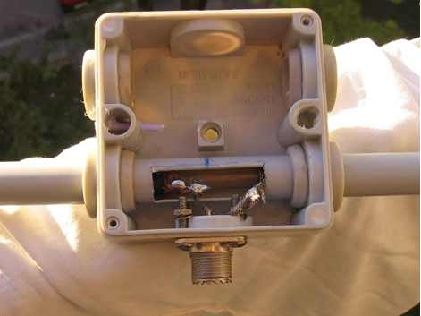
 A very essential j-pole antenna for 144 MHz. To adjust the SWR you will have to play with the 40mm distance between the coax feed and the braid inner conductor connection
 -
 A coaxial cable trap is a fundamental component in multiband antenna design, enabling a single radiator to resonate efficiently on multiple frequencies by electrically shortening or lengthening the antenna element. This project focuses on constructing such a trap for a vertical antenna operating on the 10 MHz (30m) and 14 MHz (20m) amateur bands, providing practical insights into its fabrication and integration. The article outlines the specific dimensions and winding techniques for the coaxial trap, emphasizing the use of readily available materials. It details the physical construction of the vertical element, including the mast and radiating sections, to achieve optimal performance across both target bands. The author shares personal experiences with similar trap designs, noting their effectiveness in previous horizontal dipole configurations. Key construction steps are illustrated with _original photos_, showing the assembly of the trap and its incorporation into the overall antenna structure. The design aims for a compact footprint, making it suitable for limited space installations while still delivering effective DX capabilities on the **30-meter** and **20-meter** bands.
 -
 This document provides a detailed guide on constructing and mounting a folded dipol for the 146 MHz frequency in a vertical configuration to be used in Yagi antennas. The step-by-step instructions and diagrams included make it easy for hams to build and set up this type of antenna. Understanding and implementing this design can enhance the performance of radio communication for Amateurs operating in the 2-meter band. Whether you are looking to improve your signal strength or experiment with antenna designs, this resource offers valuable insights and practical information.