Search results
Query: 40 meter
Links: 506 | Categories: 9
Categories
- Antennas > 40M > 40 meter Dipole Antennas
- Antennas > 40M > 40 meter Loop Antennas
- Antennas > 40M > 40 meter Magnetic Loop Antennas
- Antennas > 40M > 40 meter Vertical Antennas
- Antennas > 40M > 40 meter Delta Loop Antennas
- Antennas > 40M > 40 meter Yagi Antennas
- Antennas > 40M
- Radio Equipment > HF Vertical Antenna > Cushcraft R8
- Antennas > Morgain
-
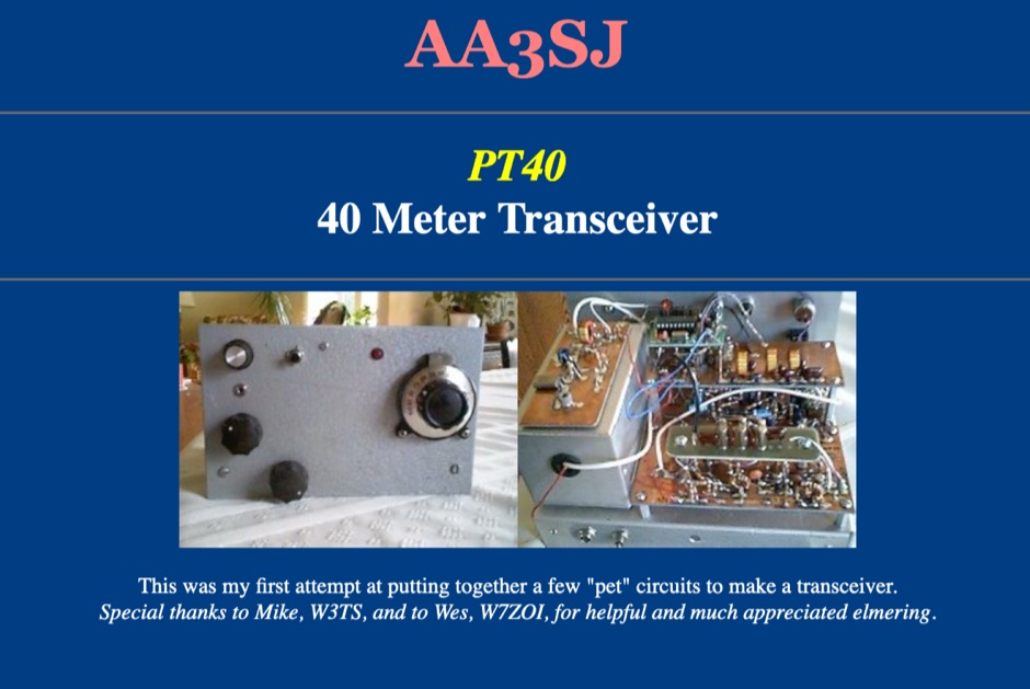 Home made 40 meter transceiver project. The receiver is a Progressive Receiver with a few modifications. The Transmitter is a modified MFJ Cub circuit. Includes schematic and circuit diagrams for Receive Input Filter, 3-Pole 500 Hz Cohn Filter and 7 MHz Double Tuned Bandpass Filter
 -
 A small magnetic loop antenna, often employed by hams facing antenna restrictions or high local RFI, offers a compact solution for HF operation. This resource details the construction of a foldable magnetic loop designed for the 40m through 17m bands, emphasizing its high-Q factor and _Faraday coupling_ for effective noise rejection and narrow-band filtering. The guide outlines material selection, advocating for copper over aluminum to maximize efficiency, and provides insights into the physics governing its operation, including impedance matching and resonance principles. Practical application of this antenna design is particularly beneficial for QRP enthusiasts and portable operators seeking a stealthy, high-performance antenna. The construction process includes specific details for a 1-meter diameter loop, a 140pF variable capacitor, and a _gamma match_ for impedance transformation. Performance comparisons suggest that while a full-size dipole might offer slightly better gain, the magnetic loop's ability to mitigate local noise often results in a superior signal-to-noise ratio, making it a viable option for challenging RF environments.
 -
 World Wide Digi DX Contest 2019 The contest will occur over 24 hours on August 31 and September 1, 2019 using the FT4 and FT8 modes on the 160, 80, 40, 20, 15, and 10-meter bands.
 -
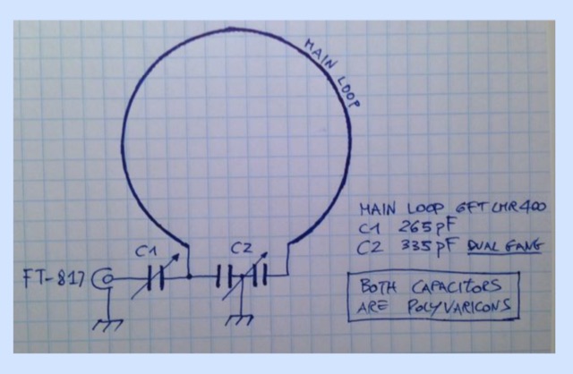 Original HF magnetic loop antenna designed by the author to work in conjunction with QRP transceivers like the FT-817 in portable operations. In this configuration the loop can operate from 30 to 10 meters. Using a two spires radiator of the same diameter it also covers 40 meters.
 -
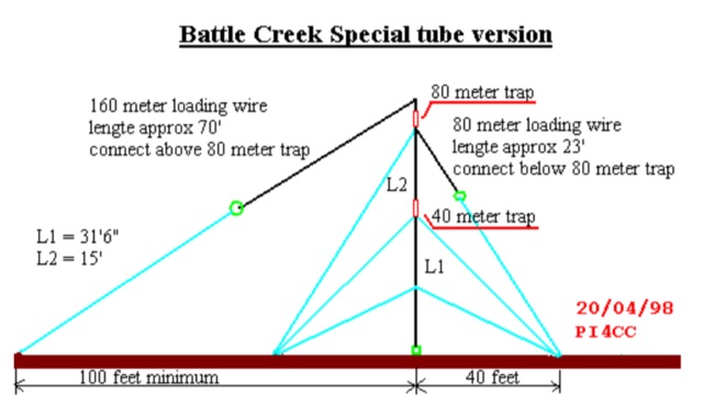 This antenna is designed for 40, 80 and 160 meters to complement a tri-band beam normally taken on DX peditions for 10, 15 and 20 meters, so six bands can be worked with only two antennas.
 -
 A rotatable 40-meter dipole antenna designed and constructed to fit within backyard constraints. The project utilized two fishing poles attached to a fiberglass center pole, resulting in an easy-to-build, lightweight, and cost-effective antenna. Essential materials included fishing rods, a center support pole, mast support, and basic tools. Linear loading was implemented to achieve the necessary length for optimal performance. The antenna, which proved effective during the contest, is ideal for field days and additional contest bands. Assembly and installation were straightforward, showcasing the antenna's practicality and efficiency.
 -
 A CW contest running every Monday, from 1630 UTC to 1729 UTC on 40 and 80 meters band
 -
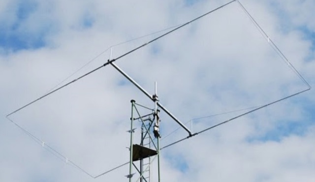 The author presents initial NEC model results for a reversible 40-meter Moxon antenna, comparing three distinct designs: a standard rectangle, a _W6NL short-tipped_ variant, and a T-hat configuration. All three models exhibit similar electrical performance, with gain figures around **5.5 dBi** and front-to-back ratios exceeding 20 dB. The primary differentiation among the designs lies in their mechanical construction and physical dimensions, which are critical for a 40-meter antenna. The rectangular Moxon requires robust support due to its element lengths, while the T-hat design offers enhanced structural integrity with slightly longer elements. The T-hat model is provisionally selected for further development, emphasizing the importance of mechanical considerations over minor electrical performance differences. Future work will focus on detailed mechanical design and construction aspects of the chosen T-hat configuration.
 -
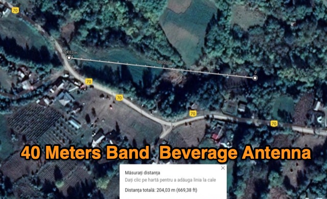 The author describes his experience building and using a Beverage antenna for the 40-meter band. Despite encountering some challenges, the antenna offered some improvements in receiving stations compared to a 3-element inverted Vee antenna. The Beverage antenna showed a significant daytime signal-to-noise ratio improvement and received signals better than the Vee antenna. However, the front-to-back ratio was not ideal, and the transmit power seemed to affect the Beverage antenna. Overall, the author concludes that the Beverage antenna might be more suitable for locations with higher noise levels. The total cost of the antenna was around 30 Euros.
 -
 The Portable EFHW antenna for the 40, 20, 15, and 10-meter bands utilizes a broadband transformer with a 1:49 ratio, designed on a PCB by either Jan or DL2MAN. The design incorporates an **FT114 core**, offering an alternative to the FT82 core. The antenna requires precisely 20.5 meters of DX Wire Ultralight for optimal performance. Additional components include DX Wires "Dyneema" 1mm rope and 1mm bricklayers string for structural support. The SWR plot indicates performance at two elevation heights: 5.5 meters (blue line) and 4 meters (yellow line), demonstrating optimization for low-elevation portable use without poles. The antenna's components, including spool and rope tensioners, are available for 3D printing, with spool dimensions scaled to 130% for a length of approximately 110mm. The design emphasizes simplicity and portability, suitable for field deployment.
 -
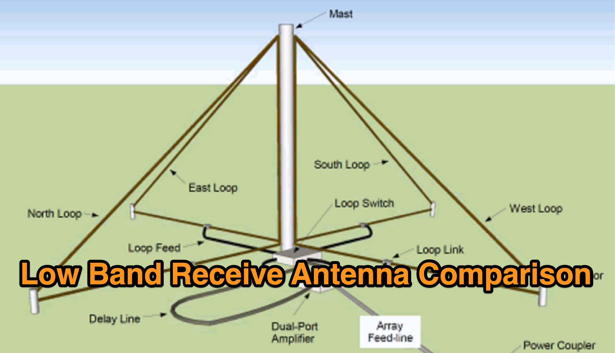 Discover the best low band receive antennas for hams with limited space. Learn about the K9AY loop antenna and Shared Apex Loop Array, two alternatives to the traditional Beverage antenna. Understand the concept of Relative Directivity Factor (RDF) and compare the performance of different receive antennas. See how the Shared Apex Loop, patented by Mark Bauman (KB7GF), offers an RDF between 8 and 10dB. Find out how to optimize antenna performance and enhance your receive capabilities on 160, 80, and 40 meters. Explore the world of low band receive antennas with insights from WB5NHL Ham Radio.
 -
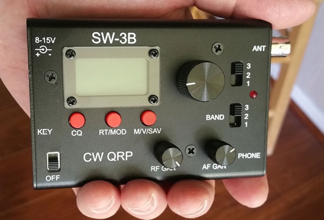 The SW-3B is a Three-band CW QRP transceiver, Weight 180g, output power 5W at 12v, 2W at 9v, works on 40 30 and 20 meters band
 -
 Demonstrates the construction and portable deployment of a 40-meter horizontal loop antenna, often referred to as a "Sky Loop" or "DX-Buster." The design adapts a full-wavelength horizontal loop for field use, eliminating the need for traditional insulators by employing four 5-meter heavy-duty _squid poles_ and metal post bases for support. This setup facilitates rapid assembly, crucial for portable operations, with the antenna wire length specified at approximately 43-45 meters for optimal 40-meter band performance. The resource details the specific construction methodology, including winding the antenna wire around rubber caps on the squid poles and securing it with electrical tape. It provides a parts list and assembly techniques, focusing on minimizing components for ease of transport and quick setup. The article, originally published in the February 2013 edition of the Central Coast ARC "Smoke Signals" magazine, reflects practical experience. This documentation offers a field-deployable 40-meter loop antenna solution, utilizing readily available components like fiberglass squid poles. It presents a practical approach for operators seeking a robust, portable antenna for the 40-meter band, emphasizing simplicity and efficiency in its design and deployment.
 -
 This article details a ham radio operator’s experience setting up HF antennas in an antenna-restricted community. Initially using an AEA Isoloop magnetic loop for QRP PSK, the author later built an attic antenna system, including dipoles for multiple HF bands and a slinky dipole for 40 meters. The setup allowed for operation on six bands with acceptable VSWR. Despite space constraints and some compromises, performance was effective. The article highlights practical strategies, emphasizing experimentation and antenna modeling for optimizing performance in limited-space environments. A valuable guide for ham radio operators facing similar restrictions.
 -
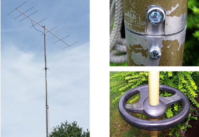 Initially planned as an article on the R-407 station mast, this project evolved into creating a custom mast kit. Utilizing original materials, the design was modified for cost-effectiveness and practicality in home assembly. The new mast extends to 10 meters, featuring secure connections, a leather-lined base to prevent metal-on-metal friction, and sturdy military-grade anchors. Modifications include lengthened connecting tubes, improved anti-rotation features, and a convenient base design for solo assembly. Ideal for amateur radio operators, this mast provides stability, ease of construction, and versatility, proving more economical than professional products without compromising on performance or reliability. Article in Czeck.
 -
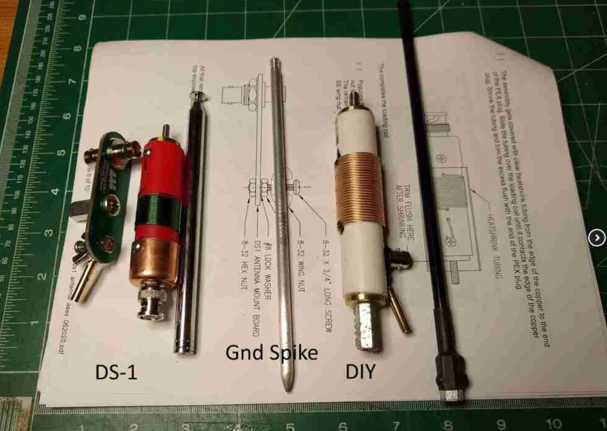 Learn how to build your own QRPGuys DS-1 40-10m short vertical antenna for ham radio operators. This page provides detailed instructions on constructing this antenna, which covers the 40 to 10-meter bands. Whether you're a beginner looking to get started with antenna building or an experienced ham radio operator looking for a new project, this resource is useful for anyone interested in DIY antennas for portable or QRP operations.
 -
 A vertical antenna project for POTA operations. This shortened antenna is aimed to work from 20 to 40 meter band implementing a loading coil, with an additional wire lenght, determined by on field testing and tuning.
 -
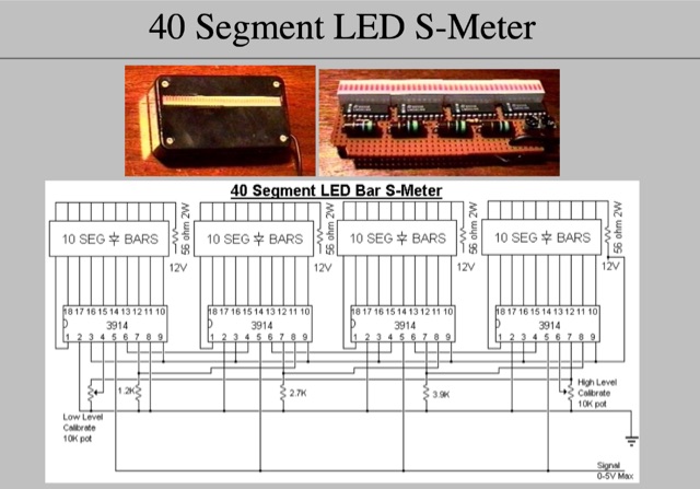 Provide your radio with a very string signal, then adjust the HIGH LEVEL pot to the threshold of illuminating the last LED (all LEDs on).
 -
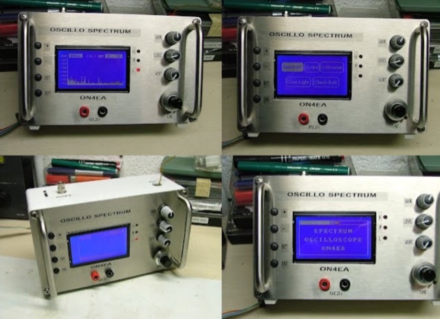 Spectrum and oscillo with tuner TV 40 MHz to 860 MHzh ome made project. This projects foreseen a multi function device providing a spectrum analyzer, scope and a voltmeter.
 -
 Addresses the common challenge of constructing effective dual-band antennas for VHF/UHF operations, specifically detailing a J-pole design. It covers the theoretical underpinnings, including calculations for quarter-wavelength radiator and stub sections, accounting for velocity factor and design frequency. The resource provides practical construction guidance using readily available materials like TV twin lead and coaxial cable, culminating in an antenna with a total length of approximately 52 inches. Performance metrics are presented, showing a measured SWR of 1.7:1 or better across most of the 2-meter band and less than 2:1 across the 70-cm band. These SWR measurements, referenced to 50-ohm impedance, were taken at the transmitter end of the feed line. The article also touches upon the necessity of a balun for proper impedance matching between the balanced J-pole and unbalanced coaxial feed line, suggesting a split-core cylindrical ferrite for this purpose.
 -
 The tri-band trapped delta loop antenna design operates on 80 meters (3.5–4 MHz), 40 meters (7–7.3 MHz), and 30 meters (10.1–10.15 MHz) using a single triangular wire loop. This configuration eliminates the need for an external antenna tuner or band-switching relays. The antenna's physical perimeter, approximately 270 feet, establishes 80M as the fundamental band, with specific trap placements enabling resonance on 40M and 30M. Trap design and placement are critical, with 30M traps positioned inboard of 40M traps within the horizontal element. Each slant leg measures approximately 80 feet. The resource references foundational information from the _ARRL Antenna Handbook_ and _ON4UN’s Low Band DXing_ regarding full-wave loop behavior and feedpoint impedances. The project aims to provide multi-band HF operation from a single, fixed antenna structure.
 -
 Optimizing directional gain on the 40-meter band often involves complex antenna designs; this resource details the construction and performance of a reversible _Moxon_ array. The design provides directional coverage from southeast to west, with a switching mechanism to reverse the pattern towards east to northwest. Key design considerations include precise element spacing, the critical role of coil inductance for proper resonance, and the use of _NEC5_ for accurate electromagnetic modeling, ensuring the antenna performs as predicted across the desired frequency range. The antenna's performance is evaluated through on-air contacts, demonstrating effective signal propagation to regions like the Caribbean, South/Central America, the US, and Europe. The article presents measured SWR plots and gain patterns, comparing them against the _NEC_ model predictions to validate the design's efficacy. Practical application notes cover mounting considerations and the benefits of its reversible pattern for targeted DXing on 40 meters, offering a robust solution for operators seeking enhanced directional capabilities without a full-sized rotating Yagi.
 -
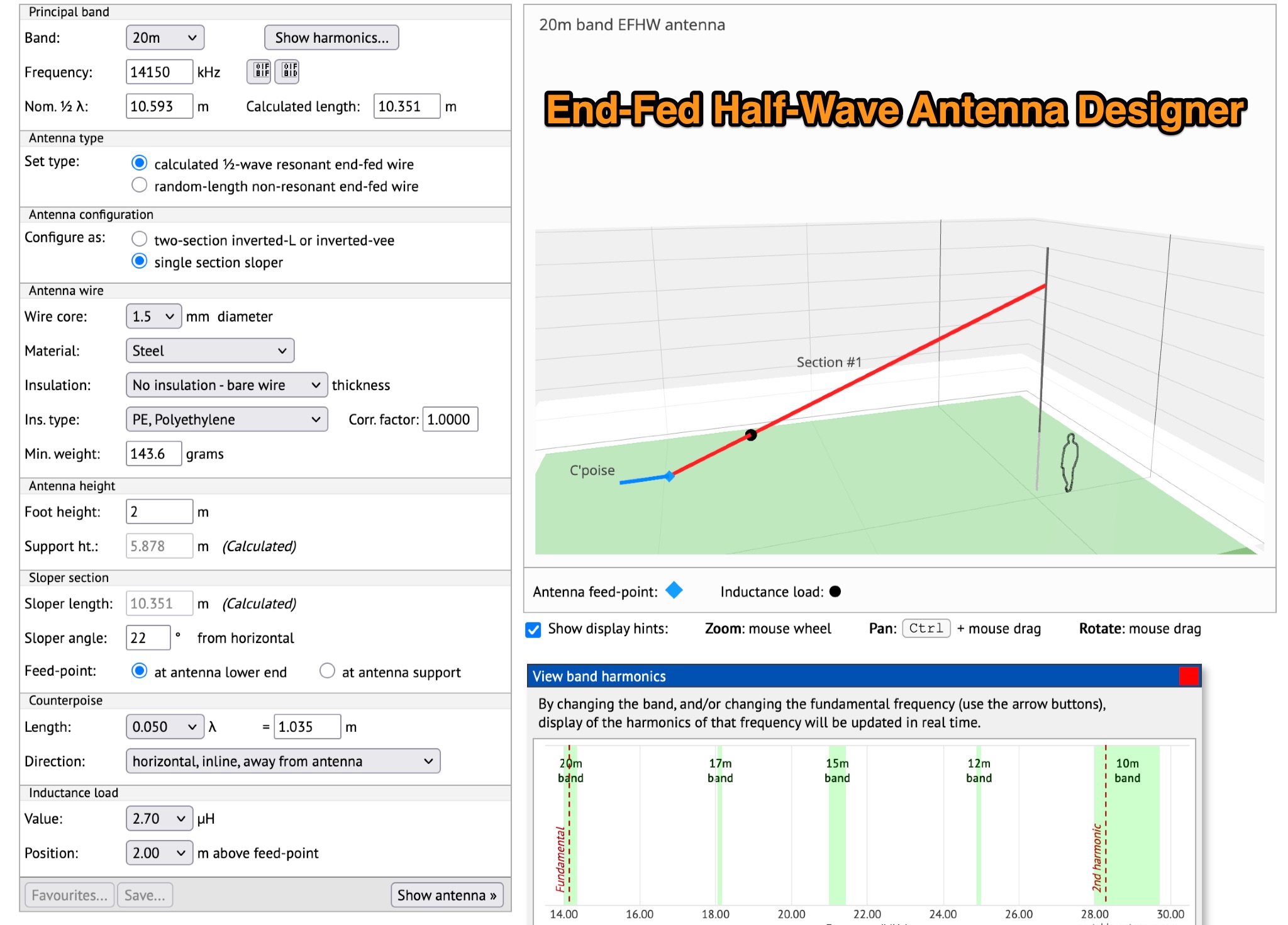 This page provides guidance on designing an End-Fed Half-Wave (EFHW) or Random-Length antenna for amateur HF bands, such as 80 or 40 meters. The content explains how to optimize the antenna for multi-band use and match it to a 50-ohm system using an unun. Hams can generate radiation patterns, VSWR charts, and antenna current diagrams for their customized antenna designs. Understanding how antenna dimensions affect performance is essential for successful field operations. The page caters to ham radio operators looking to build efficient and effective HF antennas for their stations.
 -
 The Dipole Bazooka Antenna for 40 meters is a popular choice among amateur radio operators. Its design allows for easy construction using materials like RG58 coaxial cable and PVC. Measurements are calculated using specific formulas; for instance, at a frequency of 7,100 MHz, the total length is approximately 19.74 meters. This antenna offers a performance range of 97% to 99%, with an impedance of 49 to 52 ohms. Additionally, it can handle up to 1 kW of power and requires no modifications for connection.
 -
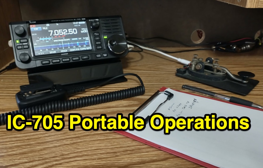 The ICOM IC-705, a popular QRP transceiver for portable operations, often presents unique challenges for field deployment. This resource details practical solutions for common portable setup issues, particularly for _Parks on the Air_ (POTA) activations. It describes a custom bracket for connecting antennas to the IC-705 through a backpack's antenna flap, utilizing a BNC female-to-female chassis mount connector to mitigate cable tangles. The author shares experiences with a DIY magnetic loop antenna, noting its ease of tuning with the IC-705 and successful CW contacts on 40 and 20 meters over distances exceeding **1000 miles**. Another modification presented is a strain relief solution for the microphone cord, replacing the standard spring clip with an easier-to-attach method. The page also mentions using a _Wolf River Parks antenna_ for POTA activations and references the QRPGuys DS-1 antenna as another portable option. Firmware updates and integration with an LDG Z11-Pro II auto-tuner are also discussed.
 -
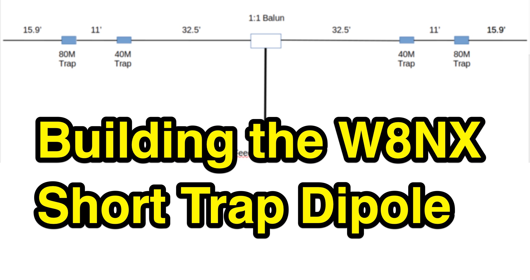 Learn how an experienced ham radio operator rebuilt his trap dipole antenna for 30, 40, and 80 meters after a storm damage. Discover the process of upgrading to a short trap dipole for 40, 80, and 160 meters using double-wound traps made from RG-58 coax. Follow along for construction details and tips on building this unique classi.
 -
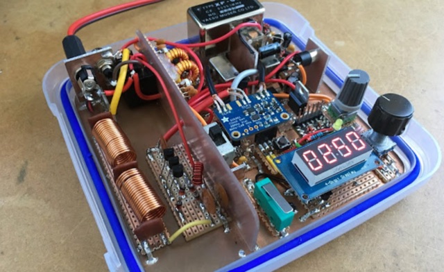 Homemade portable transceiver for the 40 meters band.
 -
 A multi-band trapped dipole antenna working on 20, 40, 75 and 160 meters band. This project implement a 20 meter trap unadilla reyco KW-20, 40 meter trap Unadilla Reyco KW-40 and a HI-Q 1:1 balun feed.
 -
 This page discusses the construction and design of a shortened 2-element Yagi antenna for the 40-meter band, focusing on the driven element. The author shares insights on adding hats to the coil to reduce losses and improve performance. The article also mentions the use of EZNEC modeling software and an AIM4170 analyzer for tuning. Amateur radio operators interested in such antenna design and optimization for the 40-meter band can find useful information and practical tips on this page.
 -
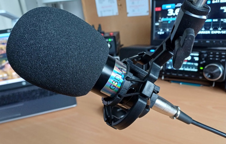 A dual insert microphone design for the Icom IC-7300 transceiver utilizes a **Besson BZ2400 M4 Rocking Armature** insert for frequencies from 500 Hz to 3 kHz, exhibiting a rising response of approximately 11 dB. A generic Electret Condenser insert, powered by the transceiver's microphone line, covers the low-frequency range from 100 Hz to 500 Hz. A Low Pass Filter is incorporated after the Electret insert to prevent frequency overlap, and a pre-set potentiometer (VR1) adjusts the low-frequency response, balancing the output of both inserts. The design emphasizes a "Close Talking" arrangement and addresses audio "colorization" by housing the Besson insert in a thick rubber holder with a foam boot, separate from the circuitry, with the Electret insert also wrapped in a foam boot. Critical importance is placed on using the correct BZ2400 M4 insert with 12 holes in its face plate. The frequency response table for the BZ2400 M4 insert shows 0 dB at 500 Hz, rising to +11 dB at 3000 Hz, while the Electret insert with the Low Pass Filter provides 0 dB at 100 Hz, rolling off to -9 dB at 500 Hz and -50 dB at 3000 Hz. This combination ensures a broad, balanced audio spectrum for SSB operation. The project includes a circuit diagram, a comprehensive parts list detailing components like a 1 Henry iron-cored inductor (L1) and various capacitors, and a board layout within the metal tube. The completed unit provides a tailored audio profile for the IC-7300, enhancing transmit audio quality.
 -
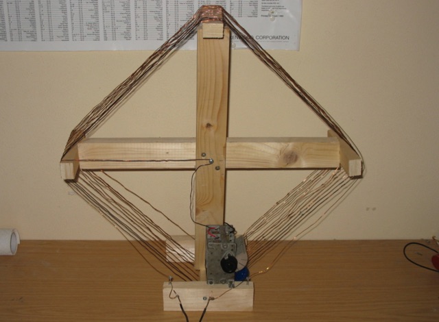 This loop antenna is intended to be connected as an antenna for receivers that do not have a built-in antenna such as an HF set or an old tube radio. This square barrel is wound on a wooden frame. It consists of two windings that are galvanically isolated from each other, a main and a coupling winding. The diameter is about 40 cm.
 -
 This page provides information on how to design an Off-Center-Fed Dipole (OCFD) antenna, suitable for amateur HF bands like 80 meters or 40 meters. The antenna design allows for VSWR minima on multiple bands, making it a good choice for multi-band use. Learn how to create an OCFD antenna in either flat-top or inverted-Vee form using a single support. The page also offers tools to generate radiation patterns, VSWR charts, and antenna current diagrams for your specific antenna design, helping hams understand performance factors. Ideal for ham radio operators looking to build their own effective antennas.
 -
 The Pikes Peak Radio Amateur Association (PPRAA) serves as an ARRL Special Service Club, providing a calendar of events and activities for its members and the wider amateur radio community. The resource details upcoming events such as the USS Pueblo Memorial Museum Ships Weekend activations, a Cubical Quad Antenna Workshop, LARCFest, and various hamfests including Dayton Hamvention and Duke City Hamfest. It also lists on-air activities like a FreeDV digital voice mode event on 10 meters, a Black Friday Simplex Event on 2M and 70cm, and a 10m event for Technician class operators, emphasizing SSB privileges from 28.300 to 28.500 MHz. The PPRAA's event schedule includes educational opportunities like a Technician Class and a Soldering Workshop, alongside social gatherings such as the PPRAA Picnic and Car Show. Past event summaries highlight successful activities like the 2024 Megafest Raffle, Winter Field Day, and multiple fox hunts utilizing frequencies like 147.420, 147.480, and 147.540 MHz. The club actively supports POTA activations, exemplified by their AF0S park activation at Cheyenne Mountain State Park, and participates in historical commemorations like the USS Pueblo Memorial operations, demonstrating a broad engagement across various amateur radio facets.
 -
 Understanding radio wave propagation is fundamental for effective HF communication, and this guide from the Galway Radio Club elucidates the principles behind _Near Vertical Incidence Skywave_ (NVIS) operation. It begins by contrasting NVIS with line-of-sight and surface wave propagation, highlighting its utility for reliable regional coverage, particularly in challenging terrains or within the skip zone. The document explains how NVIS leverages high-angle radiation, refracting signals from the ionosphere to return to Earth within a circular region, typically up to **650 km** (400 miles) from the transmitter. The guide delves into critical factors influencing NVIS, such as the _critical frequency_ (Fo) and the Maximum Usable Frequency (MUF), emphasizing their dependence on solar activity, time of day, and season. It provides practical advice on frequency selection, noting that 40 meters is often the highest daytime NVIS band, with 60 meters and 80 meters favored as darkness falls. The author, EI5DD, suggests using an ionogram for real-time propagation data, considering it more reliable than generic ham-clocks. Antenna considerations are also covered, recommending dipoles, inverted vees, or phased dipoles positioned 0.1 to 0.25 wavelengths above ground for optimal high-angle radiation. The document mentions mobile NVIS setups, including military configurations and commercial options like the Barrett Communications roof-rack antenna, which can cost around **£2000.00**. It concludes by reinforcing NVIS as an essential technique for national emergency communications, with 5 MHz (60m) and 80 meters being primary bands for daytime and nighttime operations, respectively.
 -
 Details the installation and operation of the DX Engineering TFS Series Transmit Four Square System Phasing Units, specifically models like the DXE-TFS4-160B, DXE-TFS4-80B, and DXE-TFS4-40B. It covers system components, required parts, and a discussion of vertical antenna selection, including a table of suitable DX Engineering Monoband Vertical Antennas. Installation procedures are outlined, encompassing site selection, four square layout, topographical considerations, and noise source mitigation. Specific instructions are provided for mounting the phasing unit, antenna feedline connections using 1/4-wave 75-ohm coaxial cables, and control wire routing. The document also includes details on radial system implementation, with a table of radial wire lengths for 160, 80, 75, and 40 meters, and procedures for tuning the vertical antennas for optimal performance. Operational aspects of the Four Square Control Console are described, including front and rear panel functions, control logic (Table 4), and typical transceiver/amplifier interconnections. The system enables directional control with approximately 5 dB gain over a single vertical element in four directions or an omni-directional pattern, achieving typical front-to-back ratios exceeding 20 dB. Lightning protection and initial system testing are also addressed, along with a 5 kW CW and 10 kW PEP SSB power rating and hot switching lockout feature.
 -
 VE1ZAC's analysis details the performance of **MFJ927** and **SGC239** autotuners with portable HF vertical antennas, specifically comparing 31 ft and 43 ft configurations. The resource originated from challenges encountered during a Maritime QSO Party roving operation, necessitating a lightweight and easily deployable antenna system. Target bands for the contest included 80, 40, 20, 15, and 10 meters, with a maximum power handling of 100 W CW. The author utilized a 30-foot carbon fiber push-up pole to support a vertical wire element, noting its 2 lb weight and reliability. EZNEC modeling was employed to predict performance, showing favorable results for a 30-foot vertical with elevated radials, particularly on 40 and 20 meters. Feedpoint impedance measurements, taken with an AIM4170C, are presented for various HF bands, both with and without a 41-foot RG6 stub designed to reduce reactance on 80 and 20 meters. The stub significantly improved matching on these bands, easing the tuner's workload. Operational tests revealed issues with the MFJ927's reliability during contest setup, leading to reliance on the K3's internal tuner. The SGC239, tested post-contest, performed flawlessly. A detailed side-by-side comparison covers mechanical aspects, connection options, power bias, impedance range, board quality, and documentation. Modifications to the MFJ927, including a new aluminum case, white paint for heat reduction, and upgraded impedance-measuring resistors, are also described.
 -
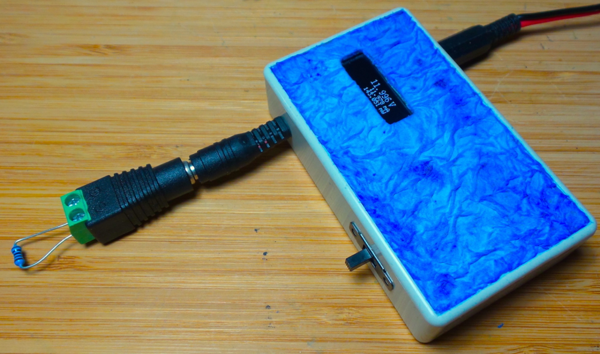 The DIY Power Meter project utilizes the _INA226_ high-side power monitoring chip, paired with an ATtiny85 microcontroller, to measure voltage, current, and power, displaying the results on a 128x32 OLED screen. The INA226 communicates via an I2C interface and is programmed with a calibration factor based on the shunt resistance and current register LSB. The project is designed to handle a maximum current of 500mA using a 0.16ohm shunt resistor, which can be adjusted to a 0.2ohm resistor, reducing the full-scale current range to 409mA with a resolution of **12.5uA**. The shunt resistor dissipates only 33mW at maximum current, making 1/4 watt resistors suitable for the setup. The PowerMeter.ino sketch configures the shunt resistance and maximum design current, automatically calculating the calibration factor. The project can be prototyped on a breadboard using an Arduino Uno, employing the Wire library for INA226 and OLED communication, and the u8g2lib library for the OLED display. For the ATtiny85 version, the Adafruit-TinyWireM and Tiny4kOLED libraries are used. The power meter is independently powered by a 3V CR2032 cell, with power switching options including manual switches or DC switched jacks. The low-side n-channel MOSFET switch configuration is tested but introduces voltage drop issues, making manual switching a more reliable option until a suitable DC switched jack is found. DXZone Technical Profile: INA226 | ATtiny85 | OLED Display | Power Meter
 -
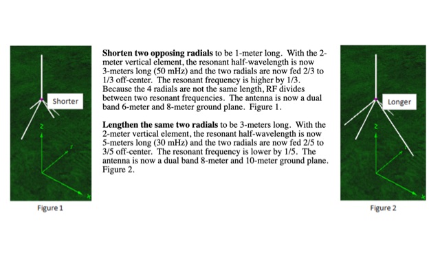 This article explains the trick of how to shorten and lengthen pairs of radials to make a 2-band ground plane antenna. Included is a "Table of Multi-Band Possibilities" covering the range of 6 to 40 meters.
 -
 A full-wave delta loop antenna, approximately 141 feet in total wire length for the 40-meter band, offers a low angle of radiation, which is highly advantageous for DX operations. This design, optimized for both 30m and 40m, leverages a specific circumference calculation of 1005/F, ensuring resonance on both bands through a simple switching mechanism. The antenna's configuration enhances long-distance communication, making it a practical choice for hams with limited space. The resource details the construction process, including the use of a _Ceramic Knife Switch_ for band selection and an _RG-11_ matching section to achieve optimal impedance. It outlines the precise loop lengths required for each band, along with tuning secrets to ensure efficient operation. Requiring a minimum height of 12 feet, this antenna can be supported by a single mast or tree limb, making it suitable for suburban installations where stealth or space constraints are a factor.
 -
 Presents DJ5IL's personal amateur radio station, detailing his journey as a licensed operator since 1973. The resource covers his **shack setup**, including an Elecraft K4D, Icom IC-7610, and various vintage transceivers like the Drake 2-B, along with a SPE Expert 1K-FA amplifier. Antenna systems include a PRO.SIS.TEL RD1524T rotary dipole for 40/20/15/10m at 15m height, an 18m vertical dipole with an SGC SG-230 tuner for 3.5-30 MHz, and an inverted-V dipole for 80m. The site features a **QSL gallery** showcasing his custom card designs and outlines his QSL policy, emphasizing the exchange of unique, personalized cards over generic confirmations. It also includes a detailed operator's biography, tracing his early fascination with radio, obtaining his license at 16, and memorable QSOs, such as a contact with his blood-relative W3NZ. The resource also delves into the historical significance of amateur radio's role in pioneering shortwave communication following the 1912 International Radiotelegraph Convention, which initially relegated amateurs to wavelengths of 200 meters and shorter. DJ5IL's philosophy on "ham spirit" is discussed, stressing the unpolitical nature of amateur radio as a global fraternity.
 -
 The RI1FJL DXpedition to Franz Josef Land, planned for August 2026, will deploy at least five high-power stations operating 24/7 across all **HF bands** for 15 days. The team of six operators, including R7AL and UA3QLC, will depart Murmansk on August 7, 2026, aboard a 20-meter sailing yacht, aiming for Heiss Island (IOTA: EU-019, QTH Loc.: LR80tn, CQ zone: 40, ITU zone: 75). Operating modes will encompass CW, SSB, and FT8, with specific FT8 frequencies like 1836.0 kHz and 14095.0 kHz designated for MSHV software. Equipment includes EE SUNSDR2 DX and Elecraft K3 transceivers, paired with Expert 1.3K-FA power amplifiers, and a variety of antennas such as Spiderbeams and phased GPs for 40m, 80m, and 160m. The expedition emphasizes working distant regions and low-power stations, acknowledging the challenging Arctic conditions with average temperatures around 1-3°C below zero. The logistical planning includes securing accommodation at the Geophysical Polar Observatory on Heiss Island and navigating potential ice conditions for zodiac landings. QSL information specifies ClubLog uploads at least daily, with OQRS available for direct and bureau QSLs. Donors contributing $10 or more receive fast LoTW confirmation and direct QSL cards, while Platinum Donors of $100+ will have their callsigns featured on the QSL card. A special plaque is offered for two QSOs with RI1FJL on different bands or modes.
 -
 Designing a collapsible 6-meter beam antenna involves careful consideration of element geometry and feedline matching, as demonstrated by VE3SMA's project. The construction draws inspiration from foldable dipole concepts and established wire beam designs like the Penn. State 40m beam and the DJ4SA Spiderbeam. Utilizing **4NEC2 modeling**, the author optimized element lengths for gain and bandwidth, observing the impact of end loops on resonant frequency and the need for compensation. Feeding the approximately 25-ohm balanced antenna with 50-ohm unbalanced cable required a specialized network. This setup incorporates a choke **balun** and a matching section built from two series quarter-wave transformers using readily available 75-ohm cable. On-the-air results validate the design, including a successful 1st double hop Es QSO with 10 Watts and satisfactory performance in the CW WW VHF Contest from FN05, where 41 grids were worked with 100 Watts, showing improved performance over a simple dipole.
 -
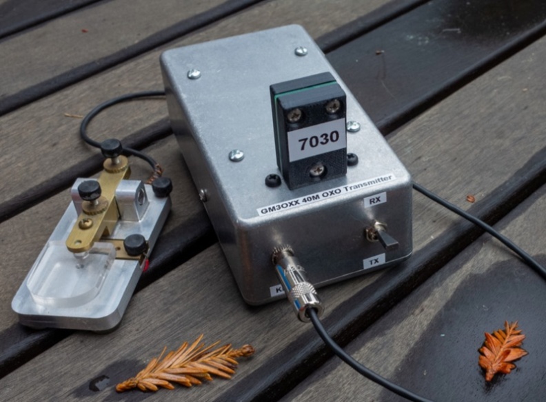 The project details the construction of a GM3OXX OXO transmitter, designed to accommodate **FT-243 crystals** using 3D-printed FX-243 holders from John KC9ON. It presents specific frequency adjustments, noting a 7030 KHz HC-49/s crystal could be tuned from 7029.8 KHz to 7031.7 KHz with an internal 45pF trimmer capacitor. The build incorporates a modified keying circuit to prevent oscillator run-on key-up and includes a TX/RX switch for sidetone via a connected receiver, with the transmitter output routed to a dummy load on receive. Practical construction aspects are thoroughly covered, including the process of cutting a rectangular opening in a diecast enclosure for the FT-243 socket and the selection of a **low-pass filter** (LPF) based on the QRP Labs kit, derived from the W3NQN design. The author achieved approximately 800mW output power from a 14.75V supply, measured with an NM0S QRPoMeter, using a 16.5-ohm emitter resistor in the 2N3866 final stage. The article also touches upon the potential for frequency agility across the 40M band using multiple FX-243 units with various crystals. The narrative includes a brief diversion into Bob W3BBO's recent homebrew projects, such as his Ugly Weekender MK II transceiver, highlighting the enduring appeal of classic QRP designs. The author reflects on the personal satisfaction derived from building RF-generating equipment, irrespective of DX achievements, and shares experiences of making local contacts with the 800mW OXO transmitter on 40 meters.
 -
 This project features a compact, 5-LED general-purpose S-Meter, designed for use with various radio circuits. It utilizes the LB1403 IC, with alternatives like LB1413, LB1423, and others. The circuit's design allows flexibility, with one version featuring a trimpot for calibration and another without it for more compact setups. The LB1423 is preferred for its low current draw and dB-calibrated scale. This S-Meter offers an efficient, customizable solution for measuring signal strength in amateur radio applications. In Portuguese.
 -
 A versatile digital VFO design utilizing the Silicon Labs Si5351a oscillator chip and Nokia 5110/3310 graphics LCD display, operating from 1-160MHz with dual VFO capability. This microcontroller-based system, powered by an ATmega328 processor, features rotary encoder tuning, selectable step sizes, RIT control, and comprehensive band memory functions. Drawing less than 40mA at 3.3V, it significantly improves upon previous DDS designs' power consumption while offering advanced features like S-meter display, VFO lock, and programmable BFO/CIO offsets. The design achieves flexible functionality through simple hardware implementation and efficient software architecture, making it particularly suitable for QRP and portable amateur radio applications.
 -
 This project outlines a simple, cost-effective 40m band HF dipole antenna design, ideal for beginners. Constructed with insulated copper wire and a 1:1 balun, it offers a 50-ohm impedance, suitable for both 40m and 15m bands due to the harmonic relationship. Calculations account for a K factor, ensuring optimal length and performance. Antenna modeling with 4NEC2 confirms practical access to both bands, though real-world results may vary. Lightweight materials and straightforward assembly make it an accessible and versatile amateur radio solution.
 -
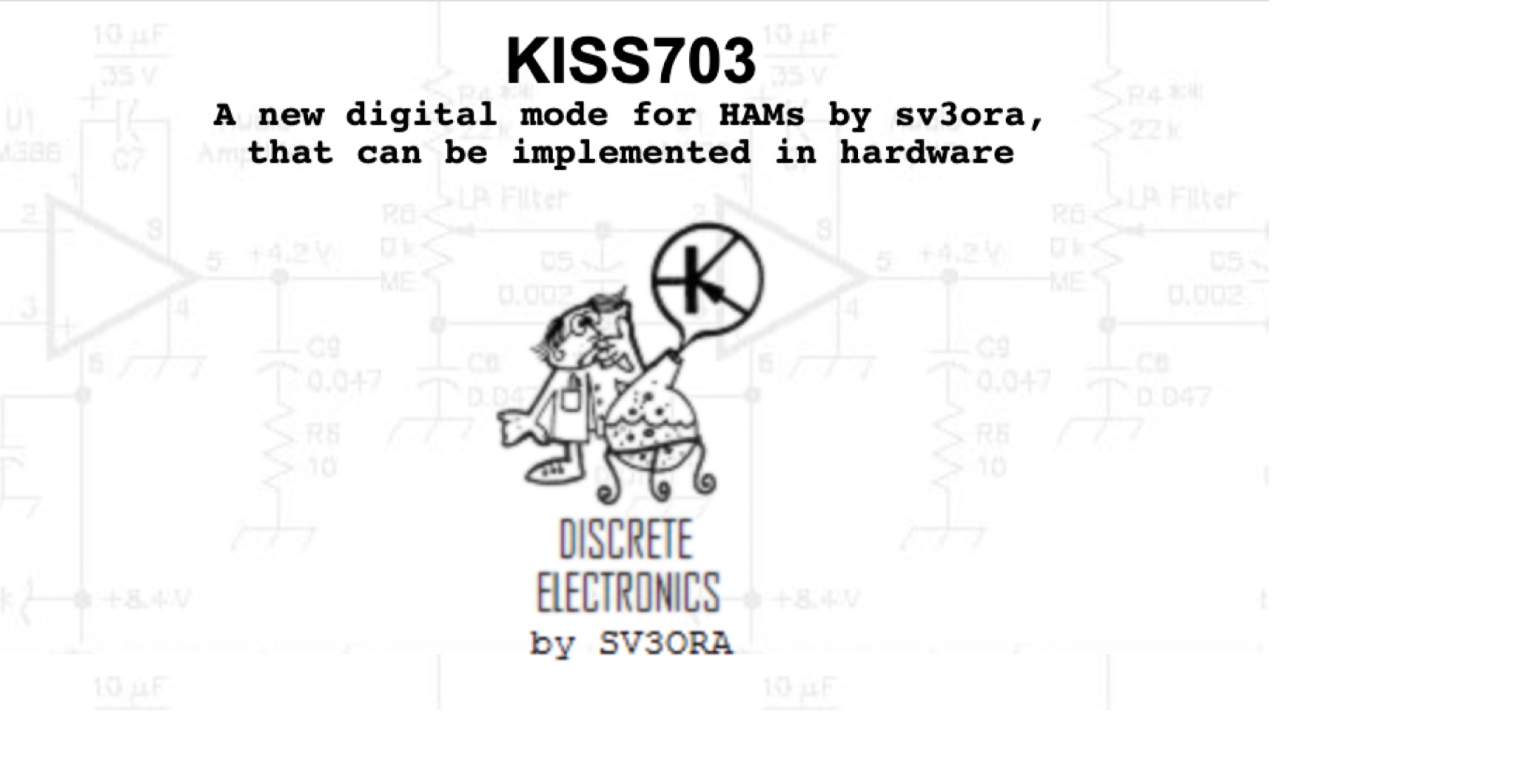 KISS703 is a 703 Hz narrowband digital mode for amateur radio, designed for simple, low-power operation without computers. A 500 Hz pilot tone ensures frequency alignment, replaced by unique tones for 37 symbols (letters, numbers, space). Built from common discrete components, it draws about 40 mA at 12 V, ideal for SOTA/IOTA use. The receiver uses amplification, wave shaping, and a pulse-counting frequency meter for manual decoding via a calibrated meter. Transmitter and receiver calibration involves marking meter positions for each tone, enabling fully self-contained messaging with minimal hardware in portable or fixed operations.
 -
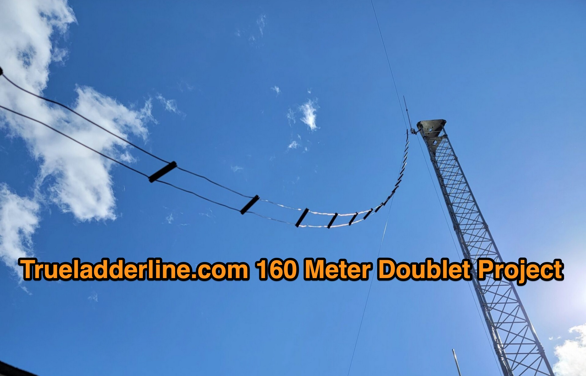 This page describes N6AQ's experience with a 160-meter doublet antenna from True Ladder Line. The operator initially attempted to install the antenna in a tree but later changed to a Rohn 45 tower for support. The antenna was upgraded to use 14ga wire instead of 16ga, and the performance was tested using an IC7300 transceiver with a 4:1 balun. Despite less than ideal setup conditions, the operator received positive signal reports on 40, 80, and 160 meters, thanks to advice from Gary at True Ladder Line.
 -
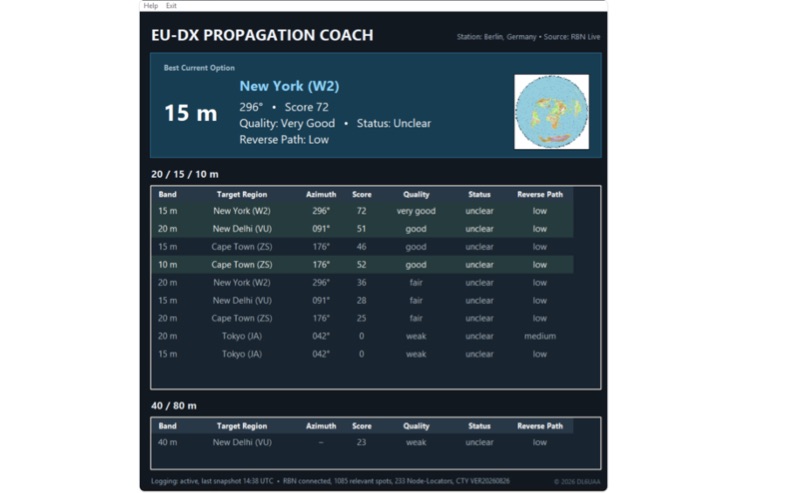 EU-DX Propagation Coach v0.9.3 processes live _Reverse Beacon Network_ (RBN) spot data, providing practical DX propagation guidance for European radio amateurs. The software offers a real-time RBN-based propagation overview, including directional guidance, enabling users to optimize band usage based on current conditions. It features five selectable European station locations and ten global DX reference centers, delivering propagation scoring for the 10, 15, and 20-meter bands, alongside a 40/80-meter overview. Dynamic azimuth and reverse-path information are calculated for each DX direction, assisting operators in precise antenna aiming. The application is distributed as a Windows ZIP archive, requiring full extraction before execution. A SHA-256 hash is provided for download integrity verification, ensuring the downloaded file matches the original. Users should note the software is provided "AS IS," and DL6UAA disclaims liability for any resulting damage or data loss. The tool is designed to run on Windows platforms, offering a dedicated utility for real-time propagation analysis.
 -
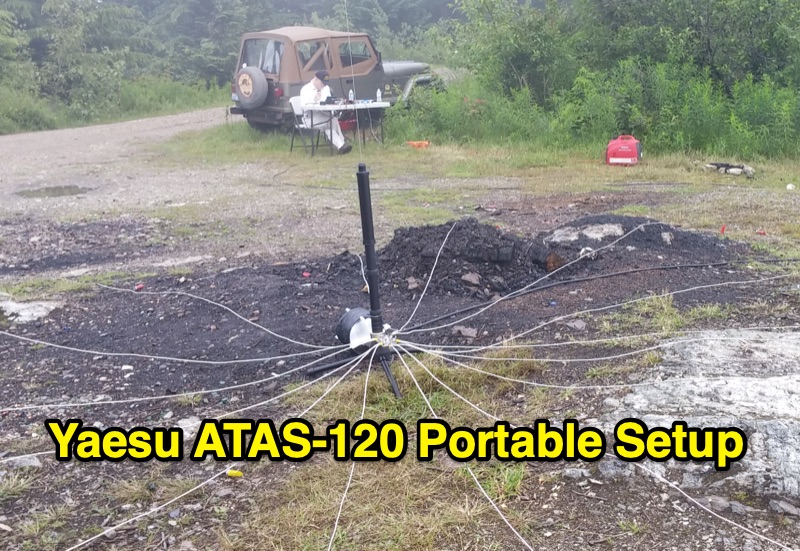 This page details a portable setup for the Yaesu ATAS-120 antenna, designed for Field Day and similar portable operations. The setup utilizes a modified music instrument stand as a base, providing a stable, low-to-the-ground platform. An antenna mounting plate secures the ATAS-120, with a PVC tube adapter fitting into the stand. The radial system consists of fifteen 0.1 wavelength radials for 40 meters (4m/13'), grouped into five sets of three wires, each attached to a ground lug. These lugs connect to bolts on the mounting plate with wingnuts, allowing the radials to spread out at 24-degree angles. The author successfully used this setup with a Yaesu FT-897D on 40m, 20m, and 15m SSB during Field Days in Western Washington, achieving East Coast contacts during daylight hours. The design emphasizes stability without the need for guy wires.