Search results
Query: di pole
Links: 724 | Categories: 17
Categories
- Antennas > 20M > 20 meter Dipole Antennas
- Antennas > 40M > 40 meter Dipole Antennas
- Radio Equipment > HF Portable Antenna > Buddipole
- Antennas > Dipole
- Manufacturers > Antennas > HF > Dipole Antenna
- Antennas > Fan Dipole
- Antennas > Folded Dipole
- Antennas > Resonant Feedline Dipole
- Antennas > 6M > 6 meter J-Pole Antenna
- Antennas > 15M
- Antennas > 30M
- Shopping and Services > Antennas
- Manufacturers > Antenna Parts > Fiberglass tubing
- Manufacturers > Antennas > HF
- Antennas > T2FD
- Antennas > W3DZZ
- Antennas > Wire
-
 A moxon antenna for the 50 MHz build with 19 feet of 14 AWG copper wire, and based on a set of PVC pipes. This is an easy to build project that will give you an efficient directional antenna on 6 meters band with low SWR on more than 1 MHz bandwidth.
 -
 This web article details the construction of a 4-meter band coaxial dipole antenna, designed for operation between **70.000 MHz and 70.500 MHz**. The resource provides a bill of materials and step-by-step assembly instructions for a half-wave dipole constructed from _RG-58_ coaxial cable. The design specifies a direct 50 ohm feedpoint impedance, eliminating the need for an external matching network. Construction photographs illustrate the stripping and soldering processes for the coaxial cable elements, ensuring proper electrical connection and physical integrity. The article includes specific dimensions for the radiating elements, derived from calculations for the 70 MHz band. The project outlines the physical dimensions required for resonance at 70 MHz, with the outer braid forming one half and the inner conductor forming the other. The feedline connection is directly to the coaxial dipole's center, maintaining a 50 ohm characteristic impedance. While the article does not present SWR plots or VNA sweeps, it focuses on the mechanical construction and dimensional accuracy for achieving a functional 4-meter dipole. The design is intended for fixed station use, with no specific mention of polarization or height above ground, but implies a standard horizontal orientation for dipole operation. DXZone Focus: Web Article | 4m Coaxial Dipole | Construction Guide | 50 ohm Feed
 -
 This design has the following advantages low-cost components, Easy to set-up - nothing to adjust, no metalwork required, and only four soldered joints!
 -
-
 Documents the construction of a **VHF/UHF** antenna addition for the Buddipole HF antenna system, leveraging the existing Versa-Tee component. The project details the fabrication of a custom antenna mount from angle aluminum, including specific drilling and tapping for 3/16"-24 bolts, and the creation of radials from Simpson Strong Tie Insulation Supports. It specifies radial lengths for 70 centimeters (6 inches from the center stud) and 2 meters (19 1/4 inches), noting the use of wire nuts for safety. The resource outlines the construction of a mast from 1/2" ID PVC conduit, connected with 3/8"-24 connecting nuts and bolts, mirroring the Buddipole's modular design. It describes the integration of a mobile dual-band antenna with a 3/8"-24 mounting stud and the custom coax setup with BNC and **PL-259** connectors. Field testing with an FT-817ND and a separate dual-band SWR meter confirmed good SWR on both 2 meters and the 440-450 MHz section of 70 centimeters, with positive reception reports during Field Day activities. Further, the article describes the creation of a custom carrying solution, including a 22-inch tripod bag and a fabric roll-up, to emulate the portability of the original Buddipole system.
 -
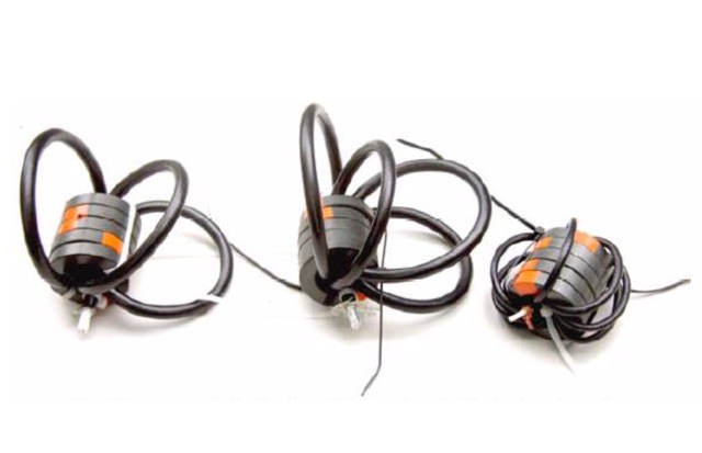
 The collinear antenna, or Marconi-Franklin antenna, is an omnidirectional, high-gain antenna composed of in-phase half-wave dipoles aligned vertically. By using quarter-wave transmission line segments, it maximizes gain at a low horizon angle, outperforming a half-wave dipole. Adding segments increases gain but narrows bandwidth. A popular DIY version, the CoCo antenna, uses half-wave coaxial cable segments connected by non-radiating transmission lines. Built with stable velocity factor cables, a matching quarter-wave sleeve balun, and ferrite rings for attenuation, the antenna achieves performance comparable to commercial models.
 -
 The antenna in this project is a modification of the techniques used to design a multiband fan type dipole with little or no tuning involved having a total space of 105 feet
 -
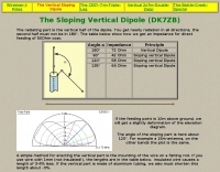 The radiating part is the vertical half of the dipole. You get nearly radiation in all directions, the second half must not be in 180°. The table below show how we get an impedance for direct feeding of 50Ohm coax. by DK7ZB
 -
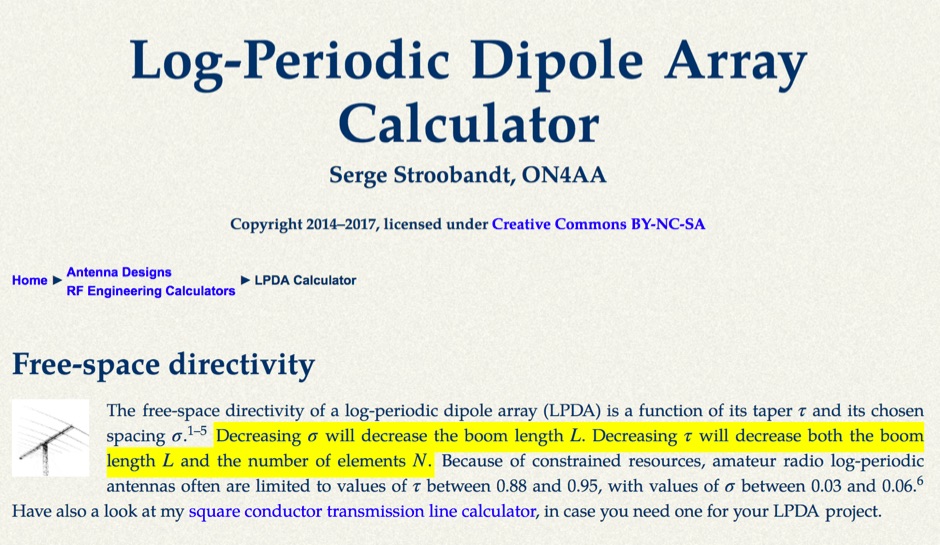 This LPDA calculator is based on the design procedure as described by L. B. Cebik, W4RNL (SK) in the 21st edition of The ARRL Antenna Handbook.
 -
 Anderson Powerpole connectors are becoming the standard for Raynet ARES and RACES groups as well as many Ham radio shacks round the world. This recourses page will give you a guide to Anderson Powerpole connectors in the radio shack.
 -
 A very popular method of making a short dipoles resonate at a given frequency. This type of antenna is suitable for single band, narrow bandwidth use.
 -
 A simple dipole for 40m band feeded with 450-Ohm openwire feedline includes MMANA Gal files to download
 -
 A simple portable antenna for SOTA VHF is described in this article dedicated to portable operations
 -
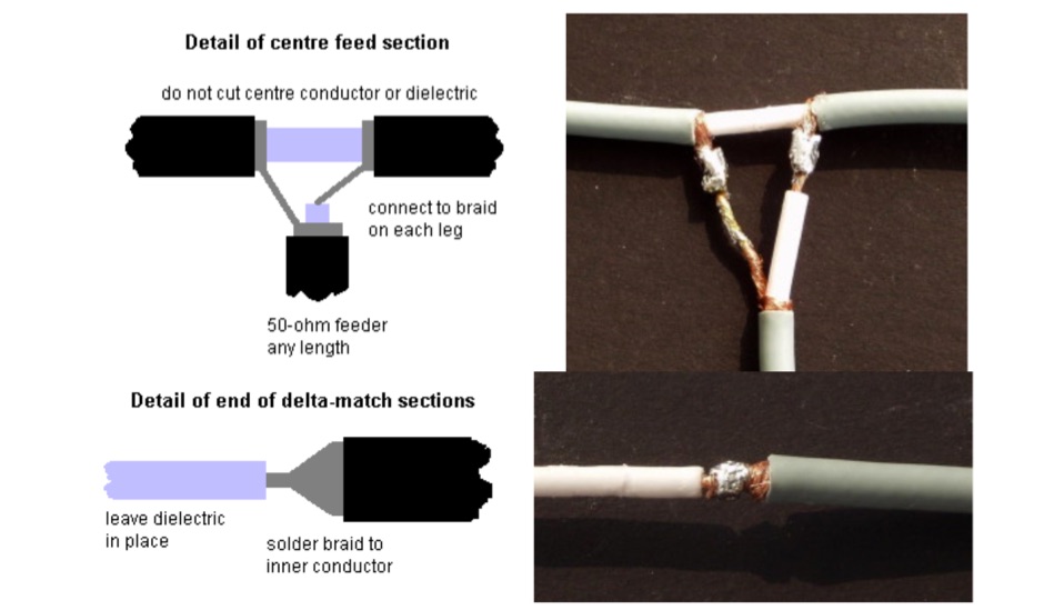
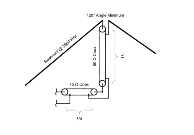 A dipole can be broadbanded by a number of techniques including by matching with resonant sections of transmission feed lines.
 -
 A monoband delta loop antenna for the 7 MHz. This vertically polarized DX Antenna is a full wavelength sngle side antenna and has a total length of 42.3 meters (137,1 inch) Can be easily setup with a flag pole or fishing pole as center top mast. For optimal performance lower side should be at 2 meter above the ground. This antenna offers a low radiation angle and 1 DB Gain.
 -
 Jose B Rivera, N2LRB, shares his initial experiences with the Icom IC-7300, recounting a shift from skepticism to appreciation for the transceiver. He details how the radio's impressive Sherwood Engineering test results, ranking it #12, significantly influenced his decision, especially considering its competitive price point against higher-end options like the Elecraft K3s. The review highlights the IC-7300's strong receive capabilities, a key factor in N2LRB's purchasing decision, and notes the advantages of its SDR architecture for future updates. He describes the straightforward setup process, from unboxing and connecting PowerPole connectors to making a first contact with N0HQ, a special event station. N2LRB expresses satisfaction with the radio's clear audio and ease of tuning, even if the pan-adapter's utility for his operating style remains to be fully explored. He concludes that the IC-7300 offers exceptional value, providing SDR features and receive performance comparable to more expensive rigs at half the cost.
 -
 Complete collection of the four main parts of this excellet research on modelling and designing half wave dipole antennas for 40 meters band, covering all aspects beginning from full wave length antennas, to shortened, loaded and reshaped dipoles
 -
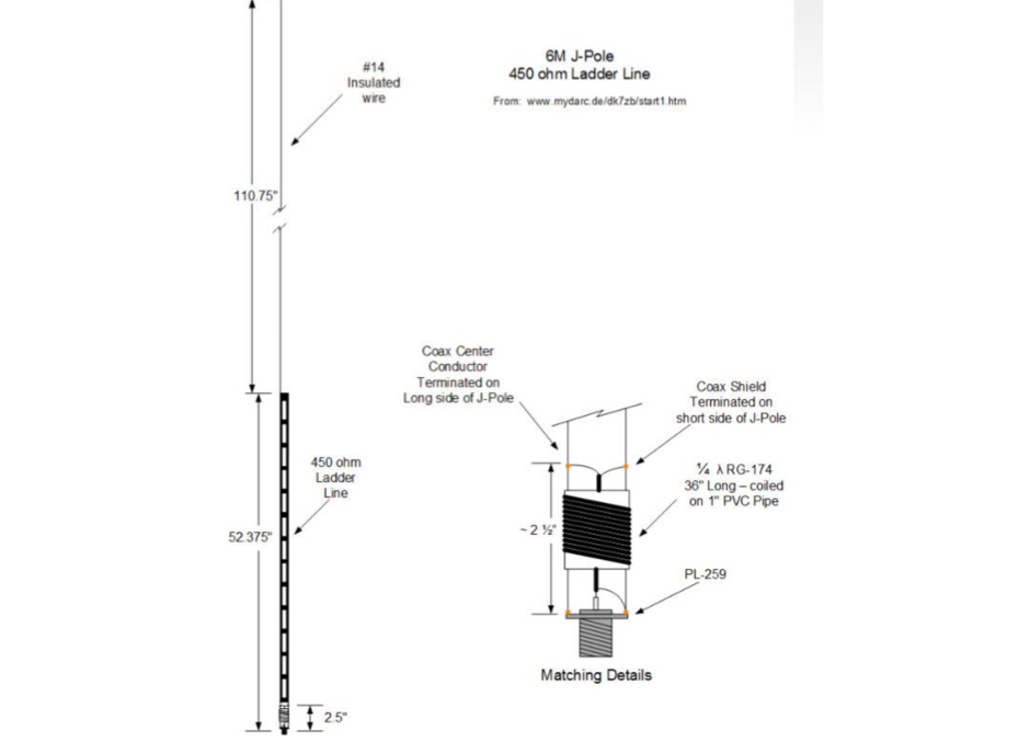 A J-pole antenna plan for 50 MHz based on the DK7ZB design
 -
 Multiband Trap Dipole, portable short antennas, accessories and kits by DG1DBM
 -
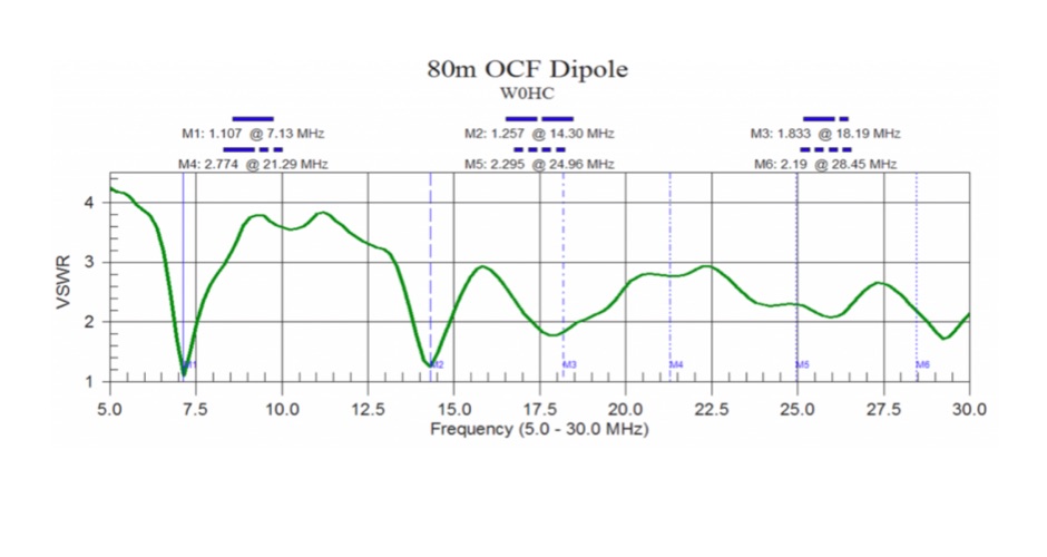
 Experimenting OCF and dipole wire antennas over house roof. Effects of roofs on wire antennas
 -
 A dual band dipole antenna for 40 and 80 meters band. Total lenght of 26 meters, foreseen two coils at aprox 11 meters distance from center feed.
 -
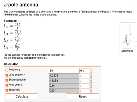 Online calculator for J-Pole antennas. The J-pole antenna consists of a short and a long vertical pole with a feed point near the bottom. The antenna looks like the letter J, hence the name J-pole antenna.
 -
-
 If you like building good antennas, this one is for you. The J-pole is a slim, omnidirectional, half-wave antenna fed at the end through a quarter-wave shorted transmission line. Its predecessor is the famous Zepp antenna developed for the Zeppelin airship.
 -
 A Six-element Yagi Beam for 6 Meter by W1JR proiddes a power gain of 10.2 dB over a dipole it is built on a 24 foot long boom
 -
 A multiband Fan Dipole that works on 40 20 15 meters band, making a folded dipole for 7 MHz band and additional element for the 21 MHz and 14 MHz
 -
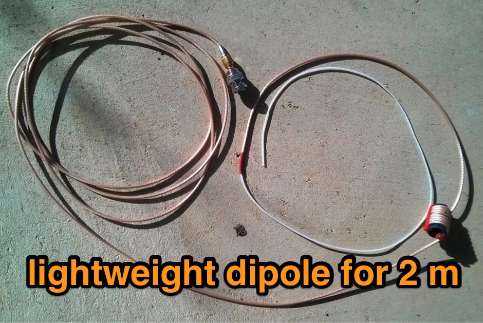
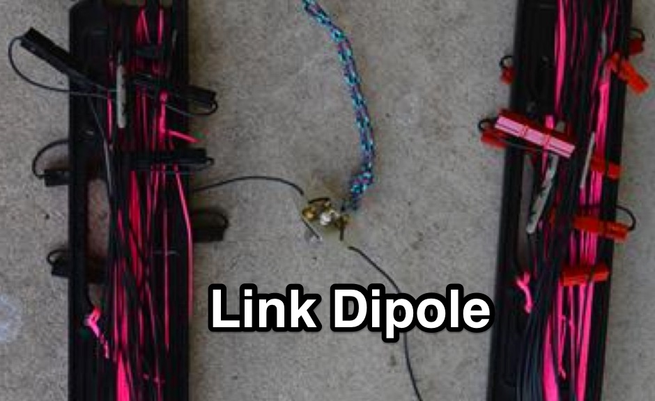 Homebrewing a Lightweight linked dipole HF antenna for portable SOTA operations
 -
 Documents the OC1I and OC6I IOTA DXpeditions to Peru, specifically highlighting operations from SA-098 (Isla La Leona) and SA-076 (Isla Lobos de Afuera). The OC1I team logged over **8000 QSOs** from SA-076, while OC6I made 1400 QSOs from SA-098, despite challenging propagation conditions. The resource details the equipment used, including an _IC-7000_, an IC-706mkIIG, and a TS-440SAT, along with various antennas such as a 160m dipole, FD4, G5RV, and a multi-band vertical for 17m, 20m, 30m, and 40m. The DXpedition dates are specified: OC6I operated from SA-098 between December 28 and December 30, while OC1I was active from SA-076 from January 2 to January 7. Both operations are confirmed as valid for IOTA credit. The page also includes a video link for the OC6I operation and a photo gallery from the DXpedition. Feedback is welcomed, and the webmaster is identified as Bodo Fritsche, DL3OCH.
 -
 In this article, author examine stresses placed on common-mode chokes (aka baluns) as hams use/abuse them, examine the efficiency of simple dipole multi- band antennas and their feed systems. Stressing a Balun.
 -
 Full article on how to build a home-made wire dipole antenna for 40 and 80 meters band. Article is fully in italian, as it was published on ARI RadioRivista, but is plenty of self explaining pictures that will guide you on homebrewing this trapped dipole antenna for the lower amateur radio bands.
 -
 An antenna for 80 meters band for those who does not have enough space to setup a halwave wire dipole that is aprox 130ft or 40 meters. The antenna is an open-wire-fed shortened dipole
 -
 An inverted V Dipole antenna for HF bands, working on 10 20 40 and 80 meters band. PDF Presentation
 -
 Roach pole vertical antenna for 40 and 30 meters band featuring good performance on short skips contacts compared to wire dipole
 -
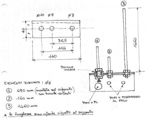 A multiband J-Pole antenna project that cover 144,220 and 430 MHz. The articles includes several pictures of this multi-band antenna, including handmade schematics and diagrams, project is mainly in Italian
 -
 Experimenting a 20 40 meter short coil loaded dipole antenna with the goal to keep the total length under 40 feet so that the dipole can be mounted on two 20 foot fiberglass pole to make a 20/40 meter rotatable dipole.
 -
 Constructing a high-performance RF spectrum analyzer up to 1000 MHz requires careful attention to component selection, shielding, and circuit isolation. This resource details a project that improves upon the _Spectrum Analyzer for the Radio Amateur_ design by Wes Hayward (W7ZOI) and Terry White (K7TAU), incorporating ideas from Scotty Sprowls' project, particularly his 1013.3 MHz IF bandpass cavity filter. The analyzer utilizes a Mini-Circuits SRA-11 mixer with a sweeping local oscillator from 1013 to 2013 MHz, feeding into a 4-pole copper pipe cavity filter. The design employs a second SRA-11 mixer with a fixed 1024 MHz LO to produce a 10.7 MHz final IF. This signal then passes through narrowband resolution filters and is processed by Analog Devices AD603 and AD8307 ICs for IF amplification and logarithmic detection, driving an oscilloscope in X/Y mode. The project emphasizes modular construction, using salvaged components and double-sided FR4 material for PCBs, with critical notes on minimizing spurious images through effective shielding and proper voltage regulation for each module. Key components include a Z-Communications V585ME48 VCO for the first LO and a Z-Comm V583ME01 VCO controlled by a Motorola MC145151 PLL for the second LO. An optional Hittite HMC307 step attenuator and K&L 5L121-1000/T5000-O/O low-pass filter manage RF input. Tuning procedures for the 10.7 MHz IF resolution filter are also detailed, showing before-and-after spectrum views.
 -
 An experimental prototype of an asymmetrical hatted vertical dipole antenna that can work on HF bands 20 to 10 meters band. The AHVD Vertical dipole is an upside-down T design
 -
-
 STAR-H Corporation specializes in extremely wideband dipoles and compact low-profile antenna systems for military, emergency management, commercial operations and consumer wireless applications.
 -
 Amateur radio antennas manufacturer based in Italy. Produces HF end-fed, dipoles, and other wire antenna types, mono band and multi band antennas.
 -
 The IK7IMP personal page provides details on the _Ham Portal_ software, an Italian-language application designed for managing amateur radio websites, including an online logbook feature. The resource also mentions the development of a J-pole antenna project, indicating a focus on practical radio construction and design. Content on the site covers general amateur radio topics, with specific mentions of equipment from manufacturers like Yaesu, Icom, and Kenwood, alongside antenna brands such as KLM and Tonna. The page serves as a hub for Icilio Carlino's amateur radio activities, offering insights into his interests in DXing, contesting (CW), and general radio operation. It also includes information relevant to the local amateur radio community in Lecce and Salento, Italy, referencing the Associazione Italiana Radioamatori (ARI) and the IQ7AF project.
 -
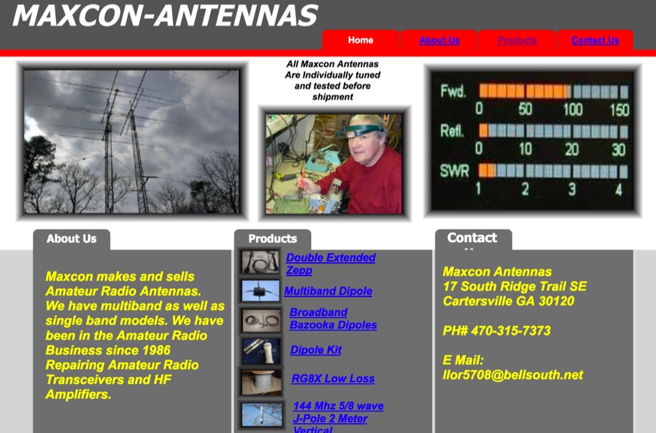 Maxcon makes and sells Amateur Radio Antennas. Double extended Zepp antenna, multiband dipoles, bazooka antennas, and VHF Jpole, made in USA
 -
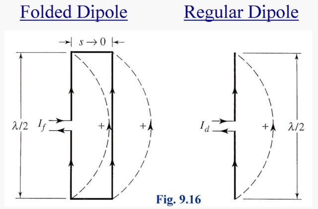 A folded dipole is an antenna, with two conductors connected on both sides, and folded to form a cylindrical closed shape, to which feed is given at the center.
 -
 A trap antenna dipole covering two differen bands made reusing an old 160/80m inverted vee antenna.
 -
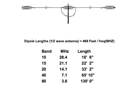
 RSGB article for beginners. How to build a dipole antenna, construction tips and correct setup of inverted-ve dipole antennas
 -

-
 This DIY vertical multi-band Windom antenna offers a practical and effective solution for amateur radio enthusiasts seeking a versatile and compact antenna for HF communications. Its simplicity of construction, multi-band capability, and favorable performance make it a valuable addition to any radio shack. The article provides detailed instructions on constructing the antenna and balun, along with diagrams and component specifications. Field tests demonstrated successful contacts with stations across Europe and North America on 14, 18, and 28 MHz. The antenna exhibited comparable performance to a W3DZZ dipole and outperformed a Cobweb antenna on 18 MHz. Low noise levels were observed, effectively suppressing background noise.
 -
 Antenna may be made practically from any wire (strand, solid) having a reasonable diameter 0.5 2.0 mm (24- 12 AWG). Antenna may be installed at any balcony of 3 to 6 meter length.
 -

-
 Sort of similar to the one of the 6m omni. Instead of using twin-lead, this design makes use of a more or less regular double bazooka antenna (coaxial dipole). Your attention shall be drawn to the available standart literature, such as Rothammel. In order to "compute" the dimension, Karl Rothammel mentioned that the total length of the dipole shall be 95% of the free-space wavelength. The short-circuit bridges (closing the folded dipole) are to be placed at a distance-fraction being equal to the velocity factor of the coax cable used, which will be 66% using RG-58 or RG174.