Search results
Query: 6 meters band
Links: 610 | Categories: 5
-
 This antenna is designed for 40, 80 and 160 meters to complement a tri-band beam normally taken on DX peditions for 10, 15 and 20 meters, so six bands can be worked with only two antennas.
 -
 A 14.12 dBi gain three elements cubical quad antenna for the six meters band. This Quad Antenna design page include a MMA model available to download and dimensions for each element.
 -
 WB8LZR details the construction and initial field results of a multi-band vertical wire antenna, designed to complement his existing horizontal loop for improved DX on 80 meters. The antenna utilizes a 67-foot vertical wire, configured as a quarter-wave radiator on 80m, and employs a 1:1 current balun for RF isolation on 80m, 30m, and 17m. For bands like 40m, 20m, and 10m, where the wire acts as a half-wave or full-wave radiator, an additional impedance transforming _unun_ is integrated to manage the significantly higher feedpoint impedance and voltage. The author notes the vertical's performance as a receiving antenna, observing reduced noise compared to his main horizontal loop, particularly on 80m, and even hearing some long-path signals the loop missed. Initial QRP contacts, including a **1-watt** QSO with a _VP2 station_ on 30m, demonstrate its transmit capability. While the radial system is currently rudimentary, the project outlines practical considerations for multi-band vertical deployment and impedance matching.
 -
 Four distinct amateur radio bands, specifically 40, 30, 20, and 15 meters, are addressed by a portable dipole antenna design. This antenna utilizes a manual switching mechanism, employing "fast-on" or flying connectors to change bands. The design is presented with an animated plan, illustrating how operators can adjust the operating frequency by opening and closing specific connections on the antenna elements. The resource describes a _4 savos dipol_ (4-band dipole) that can be shortened for specific band operation. It provides practical information for hams seeking to construct a versatile, multi-band wire antenna for portable operations or fixed station use. This design offers a straightforward approach to achieving multi-band HF capability without complex tuning units, making it suitable for field deployments like SOTA or POTA activations where rapid band changes are beneficial.
 -
 A CW contest running every Monday, from 1630 UTC to 1729 UTC on 40 and 80 meters band
 -
 Documents the A35EU DXpedition to Tonga, specifically targeting the _IOTA OC-049_ Tongatapu group during 2018. The resource outlines the operational bands from 10 to 160 meters and the primary modes utilized, including _CW_, _SSB_, RTTY, and FT8. It provides essential information for DXers interested in confirming contacts with this rare entity, detailing the logistical aspects of the operation and the specific island group activated. This page serves as an archive for the A35EU operation, offering QSL update information and confirming that all log queries were processed and a fresh log uploaded to _Clublog_. Such details are crucial for operators seeking to verify their contacts and apply for awards like DXCC or IOTA, providing a definitive record of the expedition's activity and post-operation administrative status.
 -
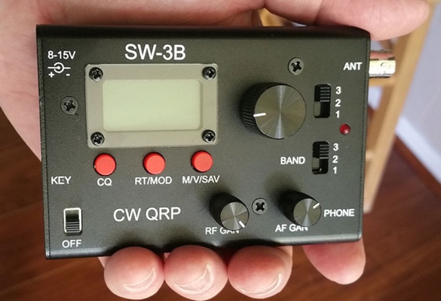 The SW-3B is a Three-band CW QRP transceiver, Weight 180g, output power 5W at 12v, 2W at 9v, works on 40 30 and 20 meters band
 -
 Presents a detailed construction guide for a 9 dB, 70cm collinear antenna, utilizing readily available _RG58/U_ coaxial cable and PVC pipe for housing. The resource outlines the critical calculations for ½ wavelength sections at 444 MHz, incorporating the coaxial cable's velocity factor of 0.66, which yields a section length of 223 millimeters. It specifies the preparation and soldering of eight such half-wavelength sections, each cut to 231mm to allow for trimming, forming the core of the array. Further instructions detail the integration of a ¼ wave element (169mm #16 solid wire) at the top and a ¼ wave aluminum tube (160mm, 5/16 inch) at the bottom, crimped to the feed point's braid. The guide also addresses RF common mode current suppression by suggesting the use of _FT50-43_ toroids on the feedline. Final assembly steps cover mounting the antenna within ¾" PVC pipe using a wooden dowel, waterproofing connections, and initial SWR checks. The article also discusses scaling the design for different element counts and other VHF/UHF bands.
 -
 Discover the best low band receive antennas for hams with limited space. Learn about the K9AY loop antenna and Shared Apex Loop Array, two alternatives to the traditional Beverage antenna. Understand the concept of Relative Directivity Factor (RDF) and compare the performance of different receive antennas. See how the Shared Apex Loop, patented by Mark Bauman (KB7GF), offers an RDF between 8 and 10dB. Find out how to optimize antenna performance and enhance your receive capabilities on 160, 80, and 40 meters. Explore the world of low band receive antennas with insights from WB5NHL Ham Radio.
 -
 A homemade quarter wave ground plane anntenna for 4 meters band.
 -
 The quarter-wave Marconi working against ground is a popular and inexpensive antenna for 160 meters. A lot of newcomers to the band favor this simple antenna because it's easy to put up, it isn't too big, and it works.
 -
 DX Pedition to Galapagos will be active from October 26th to November 7th, from 6 to 160 meters (including Warc bands) on CW, SSB and Digi modes with at least 4 stations on the air at the same time.
 -
 The article details the design and construction of a four-band Moxon beam by a radio amateur. The beam, mounted atop a rooftop tower, aimed for gain over a dipole on 20 meters, cost under $500, and included additional bands. The design features fiberglass spreaders, four bands (20/15/10/6 meters), and a single feedpoint. The construction involved computer modeling, NEC source code, and specific dimensions. The article outlines the assembly, materials, and tuning process, including in-situ adjustments for optimal performance. Despite initial challenges, the beam improved signal strength and facilitated contacts on multiple bands, marking it as the best HF antenna the author has owned.
 -
 The resource details active HF radio networks maintained by foreign ministries for diplomatic communications, specifically listing operational schedules and frequencies. It currently covers networks for Bulgaria, Czechia, Egypt, North Korea, Russia, Tunisia, and the United States. The content provides specific operational parameters for these government-run shortwave stations. Information includes details on _legacy modes_ of operation and specific transmission times. The site also includes schedules for various _number stations_ which often utilize similar HF spectrum allocations. The data presented aids in identifying and monitoring these unique, non-amateur radio signals across the shortwave bands. Specific sections are dedicated to the networks of North Korea and the United States, offering granular data for each.
 -
 A 4 element Yagi Antenna for six meters band
 -
 This article details a ham radio operator’s experience setting up HF antennas in an antenna-restricted community. Initially using an AEA Isoloop magnetic loop for QRP PSK, the author later built an attic antenna system, including dipoles for multiple HF bands and a slinky dipole for 40 meters. The setup allowed for operation on six bands with acceptable VSWR. Despite space constraints and some compromises, performance was effective. The article highlights practical strategies, emphasizing experimentation and antenna modeling for optimizing performance in limited-space environments. A valuable guide for ham radio operators facing similar restrictions.
 -
 The Portable EFHW antenna for the 40, 20, 15, and 10-meter bands utilizes a broadband transformer with a 1:49 ratio, designed on a PCB by either Jan or DL2MAN. The design incorporates an **FT114 core**, offering an alternative to the FT82 core. The antenna requires precisely 20.5 meters of DX Wire Ultralight for optimal performance. Additional components include DX Wires "Dyneema" 1mm rope and 1mm bricklayers string for structural support. The SWR plot indicates performance at two elevation heights: 5.5 meters (blue line) and 4 meters (yellow line), demonstrating optimization for low-elevation portable use without poles. The antenna's components, including spool and rope tensioners, are available for 3D printing, with spool dimensions scaled to 130% for a length of approximately 110mm. The design emphasizes simplicity and portability, suitable for field deployment.
 -
 A home made project for a 7 element yagi antenna for the two meters band based on the DK7ZB original desing.
 -
 The author describes his experience building and using a Beverage antenna for the 40-meter band. Despite encountering some challenges, the antenna offered some improvements in receiving stations compared to a 3-element inverted Vee antenna. The Beverage antenna showed a significant daytime signal-to-noise ratio improvement and received signals better than the Vee antenna. However, the front-to-back ratio was not ideal, and the transmit power seemed to affect the Beverage antenna. Overall, the author concludes that the Beverage antenna might be more suitable for locations with higher noise levels. The total cost of the antenna was around 30 Euros.
 -
 The article describes a high-gain, compact beam antenna design for the 2-meter band (144-146 MHz). The NSH 4x4 Boomer is a 4-element antenna that is mounted on a 4-foot boom with an 8.2 dB gain, 1.2:1 SWR, and a front-to-back ratio of 18 db. It is designed for mobile operations and little area, making it perfect for field usage such as disaster management. The design employs regularly spaced parts with a straightforward gamma match for tuning, and the construction materials include a square boom and polished aluminum tubes. In local and portable tests, the antenna worked regularly, achieving contact distances of up to 15 kilometers.
 -
 Explore the design and testing of a cage dipole antenna for 6 meters. Through innovative construction, witness a remarkable 77% increase in bandwidth and improved impedance characteristics.
 -
 This is a 50 MHz WebSDR receiver, located in Ashford, CT, USA FN31VU using a deltaloop turnstile horizontally polarized omnidirectional antenna.
 -
 This page provides guidance on designing an End-Fed Half-Wave (EFHW) or Random-Length antenna for amateur HF bands, such as 80 or 40 meters. The content explains how to optimize the antenna for multi-band use and match it to a 50-ohm system using an unun. Hams can generate radiation patterns, VSWR charts, and antenna current diagrams for their customized antenna designs. Understanding how antenna dimensions affect performance is essential for successful field operations. The page caters to ham radio operators looking to build efficient and effective HF antennas for their stations.
 -
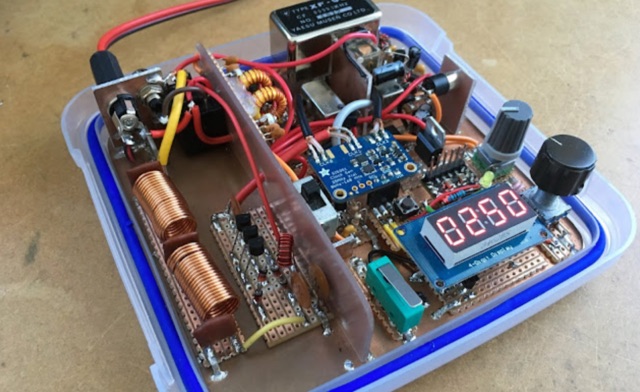 Homemade portable transceiver for the 40 meters band.
 -
 A multi-band trapped dipole antenna working on 20, 40, 75 and 160 meters band. This project implement a 20 meter trap unadilla reyco KW-20, 40 meter trap Unadilla Reyco KW-40 and a HI-Q 1:1 balun feed.
 -
 Demonstrates the construction and portable deployment of a 40-meter horizontal loop antenna, often referred to as a "Sky Loop" or "DX-Buster." The design adapts a full-wavelength horizontal loop for field use, eliminating the need for traditional insulators by employing four 5-meter heavy-duty _squid poles_ and metal post bases for support. This setup facilitates rapid assembly, crucial for portable operations, with the antenna wire length specified at approximately 43-45 meters for optimal 40-meter band performance. The resource details the specific construction methodology, including winding the antenna wire around rubber caps on the squid poles and securing it with electrical tape. It provides a parts list and assembly techniques, focusing on minimizing components for ease of transport and quick setup. The article, originally published in the February 2013 edition of the Central Coast ARC "Smoke Signals" magazine, reflects practical experience. This documentation offers a field-deployable 40-meter loop antenna solution, utilizing readily available components like fiberglass squid poles. It presents a practical approach for operators seeking a robust, portable antenna for the 40-meter band, emphasizing simplicity and efficiency in its design and deployment.
 -
 The 1/4 wavelength vertical antenna project, initially designed for 20 meters, has evolved into a versatile portable solution covering 10 through 60 meters. K0BXB details its construction, emphasizing a bottom-loaded design with a tapped loading coil and four 10-foot counterpoise wires. The author shares personal experiences and field results, including **18 QSOs** during a park activation on 17m and 30m with 10 watts, and a **2,435-mile** contact with a contest station in Bonaire on 20m using 5 watts. Comparisons are drawn to commercial offerings like the _Wolf River Coils TIA_ and _QRPGuys Triband Vertical_, highlighting the DIY antenna's small footprint, light weight, and ease of tuning for POTA activations. The resource includes insights into using test equipment such as the _NanoVNA_ for SWR optimization and discusses various radiator lengths, from 17-foot wire to a 102-inch whip, demonstrating adaptability for different portable setups. Construction tips cover coil winding, tap placement, and connecting feedlines and radials using common components.
 -
 Chavdar Levkov, LZ1AQ, presents an experimental comparison of small wideband magnetic loops, building on his previous work on wideband active small magnetic loop antennas. His research focuses on increasing loop sensitivity by maximizing the short-circuit current, which is directly tied to the "loop factor" M = A/L, where A is the equivalent loop area and L is its inductance. Levkov's methodology involves reducing inductance and increasing area through parallel or coplanar crossed (CC) configurations, comparing these designs against a reference single quad loop of 1 m2 area. Experimental verification included testing three distinct loop types: a simple quad loop, two coplanar crossed (CC) loops, and eight parallel loops, all designed to have a total geometric area of 1 m2. Measurements were conducted at 1.8, 3.5, 7, and 10 MHz using a small transmitter 270 meters away, with a Perseus direct sampling receiver for precise signal level assessment. The results consistently showed that CC loops, particularly Loop 5 (two CC circular loops with 1.44 m2 total area), yielded significantly higher currents, up to 9.1 dB over the reference loop at 3.5 MHz, validating M as a reliable predictor of loop sensitivity. Numerical simulations using MMANA further corroborated the experimental findings, demonstrating an almost perfect correlation between the calculated M factor and the induced loop current for 15 different loop models. Levkov concludes that CC loops offer superior sensitivity for a given loop area, while parallel loops are advantageous for minimizing physical volume. Practical recommendations suggest using loops with an M factor greater than 0.5 uA/pT for quiet rural environments, and he provides a spreadsheet tool, WLoop_calc.xls, to aid in optimizing loop configurations for specific operational needs.
 -
 Discover how to easily listen to amateur radio bands with insights from Frank SWL, an experienced radio enthusiast. This guide covers essential tips for tuning into frequencies between 10 meters and 160 meters using modern tools like Web SDR and Kiwi SDR. Learn about identifying callsigns, understanding Q codes, and optimizing your antenna setup for better reception. Whether you're a beginner or an experienced listener, this article provides practical advice for enhancing your radio listening experience in 2025.
 -
 The Beverage on Ground (BOG) antenna offers ham radio operators a compact alternative to traditional Beverage antennas, requiring less space and fewer support structures. This implementation, optimized for 1.8-7 MHz bands, describes ideal parameters: lengths of 60-90 meters, height of 2-10 cm above ground, and specific load resistances based on configuration. The article details experimental methods for determining optimal load resistance and presents matching systems to convert BOG impedance to 50 ohms. While less effective than classic 200-300 meter Beverages, the BOG provides directional reception in limited space, though performance varies with ground conditions and weather changes.
 -
 Discover the secrets of Six Meters with this comprehensive eBook by Jim Wilson, K5ND. Learn about the magic of 6-meter DXing, including propagation, antennas, equipment, operating software, and more. Whether you're a beginner or an experienced ham radio operator, this book covers everything you need to know. With over 8,000 downloads, this updated version includes new chapters on FT8/FT4, MSK144, and Q65 modes, as well as contesting, rover operation, and awards. Get your hands on this valuable resource and enhance your 6-meter DXing experience today.
 -
 The article by Guy Olinger, K2AV, published in the May/June 2012 National Contest Journal, introduces the Folded Counterpoise (FCP), a compact 516-foot single-wire counterpoise elevated at 8 feet, designed for 160-meter operations on small lots like 100x150-foot backyards. Originating from efforts to revive Top Band for W0UCE on a postage-stamp property, the FCP uses strategic folds to cancel ground fields within 33 feet of center, minimizing losses to 0.13-0.53 dB—outperforming sparse or on-ground radials by up to 15 dB in poor soil—while mimicking opposed radials for efficient feedpoint impedance. Paired with a critical 1:1 or 4:1 isolation transformer (e.g., trifilar on T300-2 toroid) to block common-mode currents on coax feeds, it delivers proven results: K2AV's #8 North America low-power contest score, 7+ dB gains at W4KAZ and K5AF, and over 10,000 global web hits for DIY instructions using bare 12 AWG wire and weatherproof enclosures. Ideal for acreage-challenged hams, the FCP also excels on 80 meters with scaled dimensions, offering a low-loss alternative where full radials are impractical
 -
 Come learn why it is very difficult to predict propagation on the top band. Ionospheric Variability, Time Variations of Ionospheric Parameters, Atmospheric Gravity Waves, Ionospheric Absorption and The Role of Negative Ions.
 -
 Amateur radio website dedicated to six meters band with dedicated pages on 50MHz propagation and DXing
 -
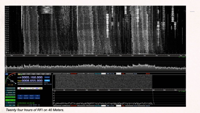 Demonstrates the application of Software-Defined Radios (SDRs) as effective tools for conducting Radio Frequency Interference (RFI) site surveys. The resource details the methodology for capturing and analyzing RFI, specifically focusing on the 80-meter band over a 24-hour period. It outlines the setup of an SDR-based survey tool, utilizing software like _S-Meter Lite_ and _Spectrum Lab_ to visualize and quantify noise sources. The article emphasizes the SDR's wideband capabilities, which allow for comprehensive identification and documentation of RFI across broad frequency ranges, crucial for effective mitigation strategies. The analysis presents practical results, illustrating how continuous monitoring can reveal intermittent RFI sources that might otherwise go undetected. For instance, the survey identified noise peaks exceeding **S9+20dB** on 80 meters during specific hours, correlating with local appliance usage. The methodology provides a repeatable process for hams to characterize their local noise floor, enabling targeted RFI suppression efforts and improving weak-signal reception, particularly for DXing and contesting.
 -
 The tri-band trapped delta loop antenna design operates on 80 meters (3.5–4 MHz), 40 meters (7–7.3 MHz), and 30 meters (10.1–10.15 MHz) using a single triangular wire loop. This configuration eliminates the need for an external antenna tuner or band-switching relays. The antenna's physical perimeter, approximately 270 feet, establishes 80M as the fundamental band, with specific trap placements enabling resonance on 40M and 30M. Trap design and placement are critical, with 30M traps positioned inboard of 40M traps within the horizontal element. Each slant leg measures approximately 80 feet. The resource references foundational information from the _ARRL Antenna Handbook_ and _ON4UN’s Low Band DXing_ regarding full-wave loop behavior and feedpoint impedances. The project aims to provide multi-band HF operation from a single, fixed antenna structure.
 -
 This page provides information on how to design an Off-Center-Fed Dipole (OCFD) antenna, suitable for amateur HF bands like 80 meters or 40 meters. The antenna design allows for VSWR minima on multiple bands, making it a good choice for multi-band use. Learn how to create an OCFD antenna in either flat-top or inverted-Vee form using a single support. The page also offers tools to generate radiation patterns, VSWR charts, and antenna current diagrams for your specific antenna design, helping hams understand performance factors. Ideal for ham radio operators looking to build their own effective antennas.
 -
 This article explains the trick of how to shorten and lengthen pairs of radials to make a 2-band ground plane antenna. Included is a "Table of Multi-Band Possibilities" covering the range of 6 to 40 meters.
 -
 The K5USS 6 Meter Hentenna Project page on Hamuniverse provides detailed instructions on how to build a 6 meter directional antenna with 3.5 dBd gain. The project is presented with permission from K5USS, Charlie of Richardson, Texas. This directional antenna is a full wave loop on 6 meters, horizontally polarized but mounted vertically, with a 50 ohm impedance, ideal for 6 meter SSB operations. The page is useful for hams looking to construct their own directional antenna for improved performance on the 6 meter band.
 -
 This page discusses the construction and design of a shortened 2-element Yagi antenna for the 40-meter band, focusing on the driven element. The author shares insights on adding hats to the coil to reduce losses and improve performance. The article also mentions the use of EZNEC modeling software and an AIM4170 analyzer for tuning. Amateur radio operators interested in such antenna design and optimization for the 40-meter band can find useful information and practical tips on this page.
 -
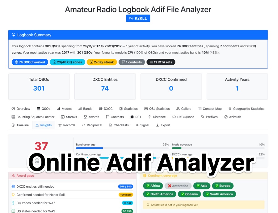 The _Amateur Radio Logbook ADIF File Analyzer_ processes ADIF files locally within the user's browser, ensuring no QSO data is uploaded to a server. It generates a visual map of contacts and detailed statistics across various parameters, including band, mode, time, grid squares, and DXCC entities. The tool offers insights into operating patterns and station performance without requiring any software installation. Users upload their ADIF log files directly, and the analysis is performed client-side, providing immediate results. The output includes charts and graphs that visualize QSO distribution and activity. This approach prioritizes user privacy and data security, as logbook information remains on the user's computer throughout the analysis process. The analyzer supports standard ADIF formats, enabling hams to quickly review their log data for trends and achievements. It is a free, open-source utility designed for general amateur radio log analysis.
 -
 This page provides a detailed review and installation experience of a new 6 and 2 meter dual band Yagi antenna. The author shares insights on the purchase process, shipping, assembly, and performance of the antenna in their backyard setup. The content is useful for hams looking for information on dual band Yagi antennas, especially those interested in improving their contest operations or backyard installations. The author's personal experience and challenges with mounting the antenna on a small push-up mast are also discussed.
 -
 This resource details the construction and performance of a compact broadband magnetic loop antenna designed for portable receiving applications with devices like the _ATS MiniRadio_. The antenna utilizes approximately 3 meters of 0.5–1 mm copper wire wound in two turns on a rhomboidal wooden frame, measuring 50 cm by 70 cm. It connects via a modified 9:1 unun, where the primary center tap is isolated from ground to improve common-mode noise rejection. The design provides untuned operation across a frequency range from the longwave band up to approximately 25 MHz. Performance characteristics include observable directivity for noise suppression and the ability to connect directly to a radio or via a 50 coaxial cable for remote operation. The article specifies the unun's 3:1 turns ratio and its SMA output for connectivity. The methodology focuses on practical construction and observed reception quality.
 -
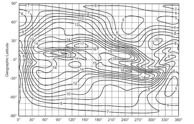
 This is a theoretical look at propagation on 630-Meters and 2200-Meters using ray tracing software. It expands on the brief discussion in the ARRL Handbooks. The Earth's magnetic field affects 630-Meter and 2200-Meter band propagation. Lower ionization reduces absorption, aiding low-frequency propagation. Differences exist between bands, limited daytime sky-wave propagation. Sunrise/sunset show promise, yet mechanisms are unclear. Ducting possible at night in specific conditions. Negative ions enhance propagation. Inefficient antennas and high man-made noise are anticipated. Groundwave propagation is significant on 2200-Meters.
 -
 This project outlines a simple, cost-effective 40m band HF dipole antenna design, ideal for beginners. Constructed with insulated copper wire and a 1:1 balun, it offers a 50-ohm impedance, suitable for both 40m and 15m bands due to the harmonic relationship. Calculations account for a K factor, ensuring optimal length and performance. Antenna modeling with 4NEC2 confirms practical access to both bands, though real-world results may vary. Lightweight materials and straightforward assembly make it an accessible and versatile amateur radio solution.
 -
 The project details the construction of a GM3OXX OXO transmitter, designed to accommodate **FT-243 crystals** using 3D-printed FX-243 holders from John KC9ON. It presents specific frequency adjustments, noting a 7030 KHz HC-49/s crystal could be tuned from 7029.8 KHz to 7031.7 KHz with an internal 45pF trimmer capacitor. The build incorporates a modified keying circuit to prevent oscillator run-on key-up and includes a TX/RX switch for sidetone via a connected receiver, with the transmitter output routed to a dummy load on receive. Practical construction aspects are thoroughly covered, including the process of cutting a rectangular opening in a diecast enclosure for the FT-243 socket and the selection of a **low-pass filter** (LPF) based on the QRP Labs kit, derived from the W3NQN design. The author achieved approximately 800mW output power from a 14.75V supply, measured with an NM0S QRPoMeter, using a 16.5-ohm emitter resistor in the 2N3866 final stage. The article also touches upon the potential for frequency agility across the 40M band using multiple FX-243 units with various crystals. The narrative includes a brief diversion into Bob W3BBO's recent homebrew projects, such as his Ugly Weekender MK II transceiver, highlighting the enduring appeal of classic QRP designs. The author reflects on the personal satisfaction derived from building RF-generating equipment, irrespective of DX achievements, and shares experiences of making local contacts with the 800mW OXO transmitter on 40 meters.
 -
 VE1ZAC's analysis details the performance of **MFJ927** and **SGC239** autotuners with portable HF vertical antennas, specifically comparing 31 ft and 43 ft configurations. The resource originated from challenges encountered during a Maritime QSO Party roving operation, necessitating a lightweight and easily deployable antenna system. Target bands for the contest included 80, 40, 20, 15, and 10 meters, with a maximum power handling of 100 W CW. The author utilized a 30-foot carbon fiber push-up pole to support a vertical wire element, noting its 2 lb weight and reliability. EZNEC modeling was employed to predict performance, showing favorable results for a 30-foot vertical with elevated radials, particularly on 40 and 20 meters. Feedpoint impedance measurements, taken with an AIM4170C, are presented for various HF bands, both with and without a 41-foot RG6 stub designed to reduce reactance on 80 and 20 meters. The stub significantly improved matching on these bands, easing the tuner's workload. Operational tests revealed issues with the MFJ927's reliability during contest setup, leading to reliance on the K3's internal tuner. The SGC239, tested post-contest, performed flawlessly. A detailed side-by-side comparison covers mechanical aspects, connection options, power bias, impedance range, board quality, and documentation. Modifications to the MFJ927, including a new aluminum case, white paint for heat reduction, and upgraded impedance-measuring resistors, are also described.
 -
 The St Paul Island CY9C DXpedition is scheduled for August 26, September 5, 2024. All bands from 160-6 meters are planned.
 -
 Assessing the ICOM IC-R9000 communications receiver, this review details its operational parameters and user experience for radio enthusiasts. Introduced in 1985, the IC-R9000 covers a broad frequency spectrum from 0.1 MHz to 1999.8 MHz, making it suitable for a wide array of listening activities from medium wave (MW) to VHF/UHF. Key performance metrics include a dynamic range of **102 dB** with the narrow SSB filter, crucial for discerning weak signals in crowded bands, and its substantial physical dimensions of 424 x 150 x 365 mm and 20 kg weight. The receiver's architecture supports various modes, though it notably lacks synchronous detection, a feature often desired for improved AM reception under fading conditions. It incorporates 1000 memory channels and robust scanning capabilities, facilitating efficient monitoring across its extensive frequency range. This analysis provides insights into the IC-R9000's capabilities and limitations, offering a historical perspective on a significant piece of amateur radio and shortwave listening hardware.
 -
 This resource presents a non-rigorous evaluation of the front-to-back (F/B) ratio of short Beverage antennas, specifically designed for low-band operation on frequencies such as 160, 80, 40, and 30 meters. The author, VE1ZAC, details the methodology used to measure the F/B ratio, which involves using a Millen Grid Dip Oscillator as a portable signal source. Measurements were taken by switching the antenna direction and recording S Meter and preamp readings to derive gain numbers. The document discusses the challenges faced in achieving accurate measurements and the assumptions made during the process, such as the calibration of S Meter units at 6 dB. This evaluation is particularly relevant for amateur radio operators interested in antenna performance on low bands.