Search results
Query: antenna cal.
Links: 1264 | Categories: 63
Categories
- Antennas > 20M > 20 meter Vertical Antennas
- Antennas > 40M > 40 meter Vertical Antennas
- Antennas > Antenna Calculators
- Radio Equipment > HF Vertical Antenna
- Manufacturers > Antennas > VHF UHF Microwave > Vertical Antennas
- Manufacturers > Antennas > HF > Vertical Antennas
- Antennas > 6M > 6 meter J-Pole Antenna
- Antennas > 6M > 6 meter Yagi Antennas
- Software > Antenna analysis
- Antennas > Theory > Antenna Gain
- Shopping and Services > Antennas
- Antennas > Vertical
- Technical Reference
- Antennas > 160M
- Antennas > 17M
- Antennas > 20M
- Antennas > 30M
- Antennas > 40M
- Antennas > 70cm
- Operating Modes > Satellites > AO-51
- Technical Reference > Arduino
- Radio Equipment > Antenna Analyzers > Array Solutions AIM 4170D
- Antennas > Bazooka
- Operating Aids > Beginner's Guides
- Shortwave Radio > Beginner's guides
- Ham Radio > Regional > Brazil
- Radio Equipment > HF Vertical Antenna > Butternut HF2V
- Antennas > C-Pole
- Shopping and Services > CB Radio Stores
- Radio Equipment > HF Vertical Antenna > Cushcraft R5
-
 Operating the _Icom IC-746_ HF/VHF transceiver often presents specific technical questions, and this resource compiles a comprehensive Frequently Asked Questions (FAQ) document in an ASCII text format. It details common inquiries and solutions related to the rig's functionality, accessories, and potential modifications. The content is structured into distinct sections addressing general information, power supplies, antennas, microphones, keyers, amplifiers, TNC integration, and optional IF filters. The FAQ provides practical guidance on topics such as configuring the internal automatic antenna tuning unit (ATU), selecting appropriate power supplies, and understanding microphone pin-outs. It also delves into advanced subjects like computer control via CI-V, wiring for PSK31 operation, and troubleshooting common issues like low S-meter readings on 2m FM or loose tuning shafts. Specific questions cover the installation of optional IF filters, comparing Inrad versus Icom filters, and optimizing filter combinations for various modes. Furthermore, the document outlines various hardware and firmware modifications, including those for increasing monitor volume, replacing LCD driver transistors, and implementing a "poor man's TCXO." It even touches upon untested modifications, such as replacing PIN diodes in the demodulator. The FAQ also lists manual errata and discrepancies, offering a robust knowledge base for IC-746 owners seeking to optimize their station or resolve operational challenges.
 -
 The **TransWorld Antennas TW2010 Traveler HF Portable Vertical Antenna** assembly video provides a visual walkthrough for deploying this popular portable HF antenna. It details the step-by-step process, from unpacking components to final setup, which is crucial for operators preparing for field day operations or DXpeditions. The video focuses on practical aspects, showing how to connect the various elements and secure the antenna for optimal performance. Operators often seek clear assembly instructions for portable antennas like the TW2010 to ensure quick and correct deployment in diverse environments. This visual aid helps clarify potential ambiguities found in written manuals, illustrating the proper handling of the antenna's radial system and telescopic elements. The video serves as a valuable resource for those aiming to achieve efficient operation with the **TW2010 Traveler** in a portable setting. Understanding the assembly sequence can significantly reduce setup time and prevent common errors encountered during initial deployments.
 -

-
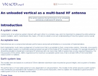 Performance of an unloaded ground mounted vertical as a multi-band HF antenna.
 -
 Demonstrates the swift setup process for a **Trans World Antenna**, showcasing its utility for portable amateur radio operations. The video highlights the antenna's design for quick deployment, a critical factor for activations like Summits On The Air (SOTA) or Parks On The Air (POTA), where efficiency in establishing a station is paramount. It illustrates the physical components and the sequence of assembly, emphasizing ease of use in varied field environments. The antenna system is presented as a multi-band solution, capable of operating across various HF frequencies. This adaptability makes it a versatile choice for hams engaging in outdoor activities or emergency communications. The visual demonstration provides practical insights into managing the antenna elements and feedline for optimal performance during temporary deployments. The focus remains on the practical aspects of field setup, rather than detailed technical specifications or performance metrics.
 -
 Ham radio HF antennas manufacturer, produce HF dynamic beam antennas, and vertical pole antenna. Offer kits and parts to build you own dynamic antennas, by IZ0AEG
 -
 HF Beam Calculator for Amateur Radio and CB Communications
 -
 The _Sci.Electronics FAQ: Repair: RFI/EMI Info_ document, authored by Daniel 9V1ZV, provides a detailed analysis of computer-generated RFI/EMI, focusing on its impact on radio reception. It identifies common RFI sources such as CPU clock rates (e.g., 4.77 MHz to 80 MHz), video card oscillators (e.g., 14.316 MHz), and even keyboard microprocessors, all of which generate square-wave harmonics across HF and L-VHF regions. The resource outlines a systematic procedure for pinpointing RFI origins, including disconnecting peripherals and using a portable AM/SW receiver with a ferrite rod antenna to localize strong interference sources. The document categorizes RFI mitigation into shielding, filtering, and design problems, offering practical solutions for each. It recommends applying conductive sprays like _EMI-LAC_ or _EMV-LACK_ to plastic casings of radios, monitors, and CPUs to create effective Faraday cages, emphasizing proper grounding and avoiding short circuits. For filtering, the guide suggests using line filters, ferrite beads, and toroids on power and data lines, and small value capacitors (e.g., 0.01 uF for serial/parallel, 100 pF for video) to shunt RFI to ground. It also discusses the use of bandpass, high-pass, low-pass, and notch filters on the receiver front-end or antenna feed to combat specific in-band noise.
 -
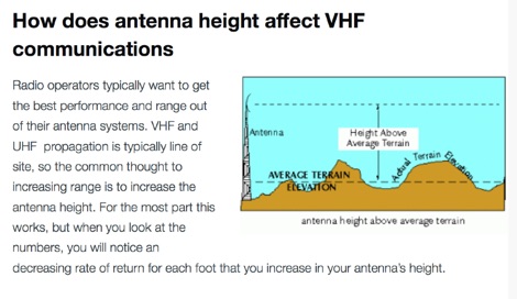 How to calculate range for a VHF antenna with a simple formula and how to increase VHF coverage.
 -
 An HF vertical antenna by N3OX with a flexible capacitance hat
 -
 An overview of coax cable often called coaxial feeder or RF cable, used to feed antennas and deliver radio frequency power from one point to another
 -
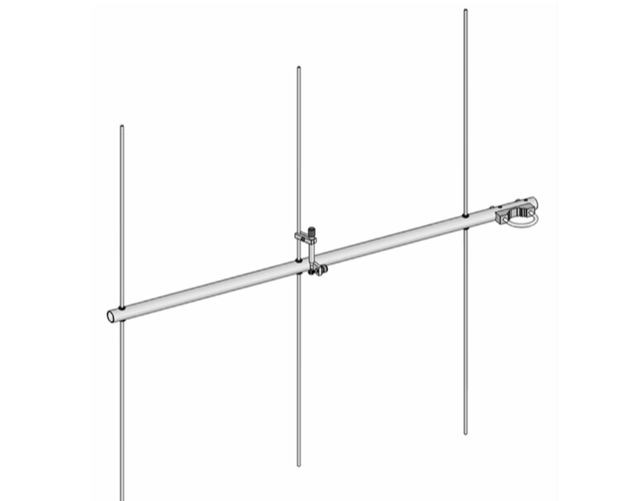
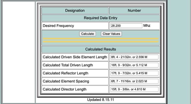 This calculator is designed to give the critical information of a particular beam antenna, in this case a three element Yagi, for the frequency chosen.
 -
 KB9AMG's Top WSPR Spots presents a focused online tool for monitoring **2-way WSPR reports**, specifically detailing propagation data from February 2026 through March 2026. This resource aggregates _WSPRnet_ data, allowing radio amateurs to observe weak signal propagation conditions across various bands. The interface is straightforward, presenting callsigns, frequencies, signal-to-noise ratios, and distances for each reported contact, which is crucial for understanding current band openings and signal paths. The utility of this WSPR spotter lies in its ability to quickly visualize global propagation. Users can identify active stations and assess signal viability over long distances, with reports often showing contacts spanning thousands of kilometers. For instance, a typical WSPR report might indicate a signal from Europe reaching North America with a _SNR_ of -25 dB, demonstrating effective low-power communication. This data is invaluable for planning DX operations or evaluating antenna performance under actual propagation conditions.
 -
 Operating a ham station often involves encountering radio frequency interference (RFI), RF feedback, or RF burns, which are frequently misattributed to poor equipment grounding. This resource meticulously dissects these assumptions, asserting that RF grounds on the operating desk often merely mask more significant system flaws. It identifies five primary causes for RF problems, including antenna system design flaws, proximity of the antenna to the operating position, DC power supply ground loops, equipment design defects, and poorly installed connectors or defective cables. The content emphasizes that issues like "hot cabinets" or changes in SWR when connecting a ground indicate substantial RF flowing over wiring or cabinets, a phenomenon known as common-mode current. The article provides detailed explanations of common-mode current generation, particularly from single-wire fed antennas like longwires, random wires, and OCF dipoles, which inherently present high levels of RF in the shack. It also illustrates how vertical antennas, lacking a perfect ground system, can excite feed lines with significant common-mode current. Through simulations, the author demonstrates how a dipole without a proper _balun_ can cause RF problems at the operating desk, showing current patterns and voltage distributions on feed line shields. The discussion extends to the proper application of _RF isolators_ and _ferrite beads_, clarifying their role in modifying common-mode impedance on cable shields and cautioning against their use as a band-aid for fundamental system defects. The resource advocates for correcting the actual source of RF problems, such as antenna system issues or poor connector mounting, rather than relying on internal shack grounding or isolators. It highlights that properly functioning two-conductor feed lines, like coaxial or open-wire lines, should result in minimal RF levels at the operating position, even without a desk RF ground. The author shares personal experience, noting that his stations since the late 1970s have operated without RF grounds at the desks, relying instead on proper antenna system design and feed line integrity.
 -
 The TransWorld Antennas TW4040 The Adventurer Monobander™ is a portable HF antenna designed for rapid deployment in field operations, including **SOTA** and **POTA** activations. This manual details the antenna's assembly, tuning procedures, and operational guidelines for optimal performance on the 40-meter band. It outlines the specific components, such as the telescoping whip and base unit, required for proper setup. Instructions cover mast erection, radial wire deployment, and impedance matching to achieve a low **VSWR** across the designated frequency segment. The document also provides guidance on antenna orientation and environmental considerations for portable use. It specifies the antenna's power handling capabilities and physical dimensions when fully deployed and collapsed for transport.
 -
 A presentation of the Yagi Antennas, and other interesting tid-bits by Brian Mileshosky. The document provides an in-depth exploration of the Yagi-Uda antenna, detailing its historical development, design principles, and performance characteristics. Originally described in the 1920s, the Yagi antenna features a driven element and parasitic elements, including reflectors and directors, which collectively determine its behavior. The document highlights how element lengths, diameters, and spacing influence gain, impedance, and directivity. It also discusses the antenna's reciprocal nature and presents data on typical gain values for various element configurations. Additionally, the text covers practical considerations, such as the construction of a "Tape Measure Yagi" for amateur use, and touches on related antenna types like dipoles and their application in Near Vertical Incident Skywave (NVIS) communication.
 -
 It is not always possible to tackle the sources of local QRM. What remains is trying to reduce the noise level by means of your antenna system. Learn how to reduce QRM and understand how cancell noises.
 -
 This article serves as a beginner-friendly guide to constructing a simple VHF dipole antenna for 2 meters, perfect for novices in the hobby. With an emphasis on affordability and simplicity, it explains the basics without overwhelming technical details. Recommendations for coaxial cable and mounting methods are provided, offering practical solutions for effective communication. By following these instructions, novices can build a functional antenna without breaking the bank.
 -
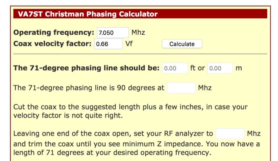 Calculate vertical array pahse antenna accorting to the Christman technique
 -
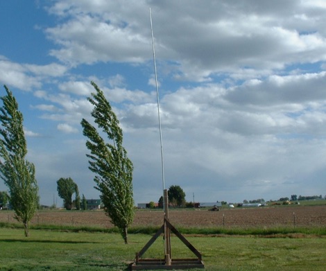 Homebrew 30 meter full quarter wave vertical antenna.
 -
 A multiband vertical antenna for HF bands with elevated ground radials slant down at 45 degrees and acting also as guy wires.
 -
 Operating the AO-51 amateur radio satellite with a handheld transceiver (HT) presents a practical entry point for newcomers to satellite communications. This resource details the necessary steps and considerations for making basic contacts, focusing on accessible equipment. It covers fundamental concepts such as _Keplerian elements_ for satellite tracking and the importance of understanding Doppler shift effects on both uplink and downlink frequencies. The tutorial outlines a straightforward approach to satellite passes, emphasizing the use of readily available gear. It provides insights into antenna orientation and timing for successful two-way communication. The content aims to demystify satellite operation, enabling operators to achieve their first **AO-51** contacts with minimal specialized equipment. Key aspects include frequency management and basic operational techniques.
 -
 Investigates the legal framework surrounding **pneumatic antenna launchers** in Victoria, Australia, specifically their classification under the Firearms Act 1996. The author, VK3KBC, details how these devices, designed to discharge a projectile by compressed air, are defined as 'firearms' and subsequently categorized as **Category E Longarms**. This classification carries significant penalties for unregistered possession or use, with the author noting the lack of provisions for amateur radio operators to legally possess and use such devices for antenna deployment. The author shares personal experiences needing such devices for portable HF radio operations, contrasting them with previously legal slingshots and current alternatives like kites or bow and arrow. VK3KBC outlines efforts to advocate for legislative change, including submissions to the Wireless Institute of Australia (WIA) and the Victorian Department of Justice, proposing an amendment to Section 3(i) of the Firearms Act 1996 to include amateur radio field operations as an exempted use. The resource also reviews the original intent of the Category E firearm classification, suggesting that pneumatic antenna launchers may have been assigned this category in the absence of a more suitable alternative.
 -
 The 160-meter amateur radio band, spanning 1.8 to 2 MHz, was historically the lowest frequency amateur allocation until the introduction of the 630-meter and 2200-meter bands. ITU Region 1 allocates 1.81–2 MHz, while other regions use 1.8–2 MHz. This band, often called "Top Band" or "Gentleman's Band," was established by the International Radiotelegraph Conference in Washington, D.C., on October 4, 1927, with an initial allocation of 1.715–2 MHz. Effective operation on 160 meters presents significant challenges due to the large antenna sizes required; a quarter-wavelength monopole is over 130 feet, and horizontal dipoles need similar heights. Propagation is typically local during the day, but long-distance contacts are common at night, especially around sunrise and sunset, and during solar minimums. The band experienced a resurgence after the LORAN-A system was phased out in North America in December 1980, leading to the removal of power restrictions.
 -
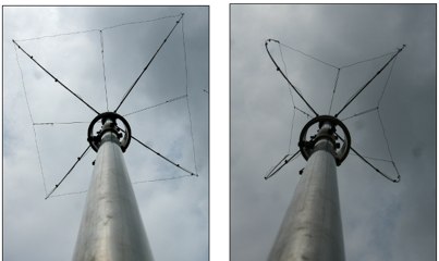
 Constructing a compact directional antenna for the 17-meter band, this resource details the build process for a Moxon rectangle, a two-element Yagi variant with folded-back elements. It covers the antenna's evolution from the _VK2ABQ beam_ and provides specific dimensions for a version built using fishing pole whips. The content includes a discussion of the antenna's radiation pattern, feedpoint impedance, and its inherent front-to-back ratio, which is often superior to a standard two-element Yagi. Practical considerations for element spacing and material choices are also addressed, alongside a visual representation of the antenna's physical layout. Performance data presented includes a comparison showing the Moxon rectangle's **2.5 dB gain** over a half-wave dipole and a front-to-back ratio of **20 dB**. The resource also touches upon the antenna's relatively wide bandwidth for a two-element beam and its suitability for portable operations due to its compact footprint. It offers insights into optimizing the design for specific operating conditions and discusses the advantages of its lower take-off angle compared to omnidirectional wire antennas, making it effective for DX contacts on the 17-meter band.
 -
 The Superantennas MP-1 portable HF antenna is analyzed for its design and field performance, particularly its high-Q loading coil and 3/8-inch mounting. The review details the antenna's construction, including an 8-inch vertical section, a large-diameter loading coil tuned by a sleeve, and a 4-foot whip that disassembles into six rods for transport. Initial testing with the supplied 10-foot ribbon cable "ground plane" yielded poor SWR and RF hot conditions, indicating an inadequate ground system. Further experimentation with longer radials and resonant counterpoises for each band improved matching and eliminated RF hot issues, but introduced significant operational complexity. The author notes the difficulty in optimizing both counterpoise length and coil setting without an antenna analyzer, and the sensitivity of the MP-1 to counterpoise deployment. The review also discusses the recommendation to tune for maximum received signals rather than minimum SWR, often necessitating an external ATU due to the antenna's typical low impedance. The **MP-1**'s critical dependence on resonant counterpoises for effective operation, especially when elevated, is highlighted as a major drawback for portable use. The author ultimately sold the antenna, concluding that despite its sound technical design, its fussy nature and the need for extensive counterpoise management or an ATU detract from its portability and convenience compared to simpler, less expensive dipole solutions. The **Superantennas MP-1** is deemed a flawed portable antenna, requiring considerable effort to achieve its claimed performance.
 -
 This article deal with various means to covertly operate radio systems while going unobserved.
 -
 Over 15 years of operational notes are documented on the AA6E Station Log, covering diverse amateur radio topics. The blog presents detailed accounts of station setup, antenna experiments, and digital mode operations, often featuring specific equipment like the _Ten-Tec Orion_ transceiver. It includes practical discussions on **station grounding techniques** and insights into PSK31 Morse code communication. The resource provides a chronological record of Martin Ewing's amateur radio activities, offering firsthand perspectives on equipment performance and operational challenges. Content often includes technical observations and solutions developed through practical experience, such as optimizing antenna systems for various bands. Specific entries detail contest participation and DX chasing, providing context for operational decisions and results.
 -
 137 kHz propagation analysis details ground wave and sky wave mechanisms, drawing heavily from **CCIR Rec. 368-6** for ground wave field strength predictions and **CCIR Rep. 265-7** for sky wave modeling. The resource presents field strength values for 1 W ERP at varying distances, considering ground conductivity and permittivity for ground wave, and ionospheric height (70km daytime, 90km nighttime) for sky wave. Key factors like ionospheric focusing (factor "D"), reflection coefficient ("RC"), and antenna ground pattern factors ("Ft", "Fr") are quantified for 137 kHz, enabling calculation of sky wave field strength. Practical coverage ranges are derived for 137 kHz, showing useful ground wave coverage up to 1600 km over seawater and 1100 km over average ground, assuming a -9 dBuV/m noise floor. Sky wave coverage extends beyond 2200 km during night-time and winter daytime, but is negligible during summer daytime at solar minimum. The document also compares ground wave and sky wave strengths, identifying crossover distances at 550 km (night-time), 750 km (winter daytime), and 1250 km (summer daytime), where interference fading can occur. Adjustments for solar maximum conditions are provided, indicating 2-11 dB higher sky wave values depending on distance and season.
 -
 A considerably shortened Magnetic Loop antenna with performance of a single conductor text book magnetic loop.
 -
 An easy to build and extremely high performance antenna, works perfectly on all HF bands 3.5-28 MHz with some compromises, it is basically an half wave dipole for 40-80 meters, an LC circuit or trap 40 meters allows you to use a single radiating element.
 -
 How manage and quantify ground loss in vertically-polarized antennas by VE3VN
 -
 A helically wound vertical antenna experiment. 14 meter of wire wounded on a 8 meter fishing pole with 4 elevated radials
 -
 A simple, cheap and easy to build 26 feet long vertical antenna that works DX on 20 - 10 meters including WARC Bands, it is designed for portability for field days, camping, or permanent installation, cost, and to achieve at least 1/2 wavelength on the WARC bands.
 -
 Announces the retirement of Brand Electronics, a manufacturer specializing in **power meters** and various ham radio accessories, effective 2025. The company has served the amateur radio community for over 35 years, providing equipment for station setup and operation. The product line historically included accessories compatible with major transceivers from Icom, Yaesu, and Kenwood, alongside components and technical references for homebrew projects. Their offerings supported accurate RF power measurement, crucial for optimizing antenna systems and ensuring legal limit compliance. This notice serves as a final update regarding the company's operational status, marking the cessation of manufacturing and sales activities. The site provides no further details on product support or inventory liquidation.
 -
 The article, "Using 75 Ohm CATV Coaxial Cable," details methods for employing readily available 75-ohm CATV hardline in standard 50-ohm amateur radio setups. It addresses the inherent impedance mismatch and practical considerations, such as connector compatibility, for hams seeking cost-effective, low-loss feedline solutions. The resource specifically contrasts common 50-ohm cables like RG-8, RG213, and _LMR-400_ with 75-ohm hardline, highlighting the latter's lower loss characteristics, particularly at VHF and UHF frequencies. It explores two primary approaches to manage the impedance difference: direct connection with an acceptable SWR compromise and precise impedance transformation. The direct connection method acknowledges that a perfect 1:1 SWR is not always critical, especially when using low-loss coax. For impedance transformation, the article explains the use of half-wavelength sections of coax to reflect the antenna's 50-ohm impedance back to the transmitter, noting its single-frequency effectiveness. It also briefly mentions transformer designs using toroid cores and a technique involving two 1/12 wavelength sections of feedline for broader bandwidth. The content further clarifies the concept of _velocity factor_ for calculating electrical versus physical cable lengths, providing a generic formula for precise length determination. It notes that while half-wave matching is practical for 10 meters and above, it can result in excessively long runs for lower bands like 160 meters, potentially adding **250 feet** of cable. The article also mentions achieving a usable bandwidth of 28.000 MHz up to at least **28.8 MHz** on 10 meters with specific transformation techniques.
 -
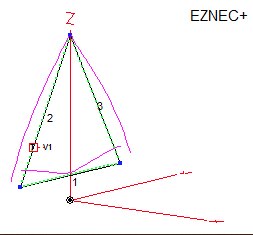
 Design for a quarter wave vertical antenna, for the top band in use at V31YN
 -
 A 7 dB directional gain is reported for this portable VHF Yagi antenna design, which utilizes cut metal tape measure sections for its elements. The resource details the construction process for a 2-meter band antenna, emphasizing its ease of build and portability. It specifically mentions the design's suitability for radio direction finding (RDF), fox hunting, and communication with satellites and the International Space Station (ISS), highlighting its practical applications for amateur radio operators. The construction cost is estimated at under $20, with potential for even lower expense if salvaged materials like old tape measures and PVC pipes are used. The article references _Joe Leggio's_ (WB2HOL) original design, noting specific alterations made by the author. It also compares this design to other DIY Yagi antennas, including _FN64's_ 2-meter band and _manuka's_ 70-cm band tape measure Yagis, underscoring its unique combination of simplicity, portability, and effective performance with a 1:1 SWR achievable on the 2-meter band.
 -
 1.5 dB of matched line loss can be calculated for a given transmission line using this online tool, which employs a model calibrated from empirical data. The calculator allows radio amateurs to input specific transmission line types, such as _RG-8_ or _RG-58_, and then determine the expected signal attenuation. This is crucial for optimizing antenna system efficiency and understanding power delivery to the radiating element, especially for HF and VHF operations where feedline losses can significantly impact performance. Beyond matched loss, the calculator also provides an estimate for mismatched loss if the Standing Wave Ratio (SWR) is specified. This feature helps operators quantify the additional power loss due to impedance discontinuities between the transceiver, feedline, and antenna, which is a common concern in amateur radio installations. Accurate loss calculations are vital for effective station design and for predicting actual radiated power. The tool's utility extends to various operating scenarios, from fixed station setups to portable deployments, aiding in the selection of appropriate feedline lengths and types to minimize signal degradation. Understanding these losses is a fundamental aspect of maximizing the effectiveness of any amateur radio antenna system.
 -
 A 102-inch vertical whip, commonly a CB antenna, forms the core of this low-profile 10-meter antenna design, optimized for the 28 MHz band. The construction details specify three 8-foot radials made from scrap wire, connected to a common point. This simple yet effective setup is designed for ease of construction and deployment, making it accessible for operators with limited space or materials. The design emphasizes using readily available components, including PVC pipe for the mast and a SO-239 connector for the feedline, ensuring a straightforward build process for a resonant quarter-wave vertical. Field results indicate that this antenna provides good performance for local and DX contacts on 10 meters, despite its compact footprint. The author, N8WRL, shares practical insights into its construction and tuning, highlighting its suitability for temporary or permanent installations where a full-sized antenna might be impractical. Comparisons to more complex designs suggest that this low-profile vertical offers a respectable signal-to-noise ratio and effective radiated power for its size, proving that simple designs can yield satisfying on-air results.
 -
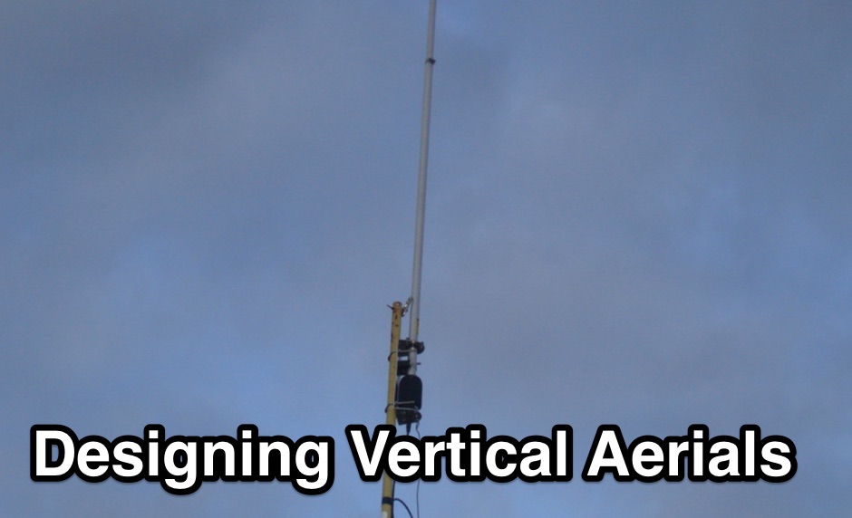 If you want to design vertical antennas you can find all theory and formulas used to model a vertical aerial calculating capacitance, reactance, building the inductor and calculating resistances. Includes an excel spreadsheet to calculate efficiency.
 -
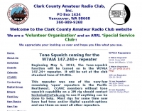 Clark county amateur radio club serving sw washington for 75 years! come find out how our local ham club offers programs that cover everything from the history of morse code and call signs to ham radio antennas
 -
 A page describing how to home made a custom 9:1 balun for a common portable wire antenna. The author suggest to use 4C65 or FT140-61 toroids instead of the common Amidon T200-2
 -
 Gold Line, a manufacturer, provides a range of professional audio test and analysis equipment, including specific products like the **ZM1 Impedance Meter**, which is relevant for amateur radio operators needing to characterize antenna systems. The site also lists various noise sources and microphones, such as the TEF04 Mic, indicating a focus on audio signal integrity and measurement. The resource details contact information for repairs, calibration, quotations for specific products like the ZM1 and ZM1P, and technical support, with distinct email addresses and phone numbers provided for each function. This structured contact approach facilitates direct engagement with the appropriate department for specific inquiries. Operational changes effective March 1, 2019, are noted, directing users to VLDESIGN for repair and calibration, and to Partha Chen for ZM1/ZM1P quotations. Louis Pittsley is designated for technical support, with a general inquiry phone number also available, outlining the company's support infrastructure.
 -
 This web article details the construction of a 4-meter band coaxial dipole antenna, designed for operation between **70.000 MHz and 70.500 MHz**. The resource provides a bill of materials and step-by-step assembly instructions for a half-wave dipole constructed from _RG-58_ coaxial cable. The design specifies a direct 50 ohm feedpoint impedance, eliminating the need for an external matching network. Construction photographs illustrate the stripping and soldering processes for the coaxial cable elements, ensuring proper electrical connection and physical integrity. The article includes specific dimensions for the radiating elements, derived from calculations for the 70 MHz band. The project outlines the physical dimensions required for resonance at 70 MHz, with the outer braid forming one half and the inner conductor forming the other. The feedline connection is directly to the coaxial dipole's center, maintaining a 50 ohm characteristic impedance. While the article does not present SWR plots or VNA sweeps, it focuses on the mechanical construction and dimensional accuracy for achieving a functional 4-meter dipole. The design is intended for fixed station use, with no specific mention of polarization or height above ground, but implies a standard horizontal orientation for dipole operation. DXZone Focus: Web Article | 4m Coaxial Dipole | Construction Guide | 50 ohm Feed
 -
 Aka Circular Waveguide Antenna. This online antenna calculator let you plan your cantenna for the desired frequency of operation, giving the Can diameter you have available.
 -
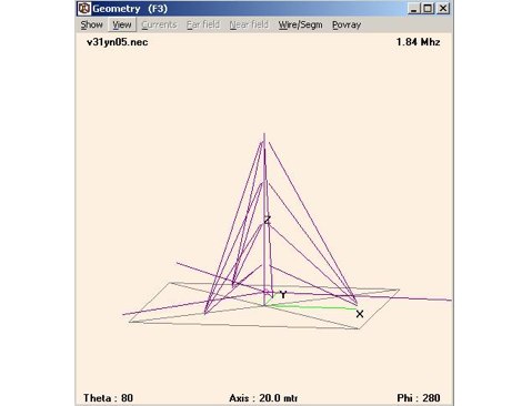
 Presentation about Practical Antenna Modeling Using the NEC Codes with examples of HF wire antennas and 4NEC2. How to define and edit the models, Running the simulations, Work some examples, Variables usage, Deal with Feed Lines and ground
 -
 On this page you will find information about previous, current and future operations of our contest team, different articles, links and info about contesting, DXing, contests calendar, propagation, antennas, equipment, awards, and much more.
 -
 The collinear antenna, or Marconi-Franklin antenna, is an omnidirectional, high-gain antenna composed of in-phase half-wave dipoles aligned vertically. By using quarter-wave transmission line segments, it maximizes gain at a low horizon angle, outperforming a half-wave dipole. Adding segments increases gain but narrows bandwidth. A popular DIY version, the CoCo antenna, uses half-wave coaxial cable segments connected by non-radiating transmission lines. Built with stable velocity factor cables, a matching quarter-wave sleeve balun, and ferrite rings for attenuation, the antenna achieves performance comparable to commercial models.
 -
 SPX Communication Technologies, operating under the TCI International brand, presents a range of radio frequency (RF) solutions primarily for government, defense, and commercial sectors. The offerings include advanced systems for spectrum monitoring, communications intelligence (COMINT), and high-frequency (HF) and medium-frequency (MF) broadcasting and communication antenna systems. Specific product lines encompass _Blackbird_ COMINT systems, _Scout_ spectrum monitoring receivers, and various antenna arrays designed for robust performance in challenging RF environments. The resource details the capabilities of these systems, such as wideband signal detection, direction finding (DF), and signal analysis, crucial for intelligence gathering and regulatory compliance. It also highlights the engineering behind their antenna designs, which are optimized for specific frequency ranges and operational requirements, including high-power broadcast applications and secure military communications. The information presented emphasizes the integration of hardware and software for comprehensive RF situational awareness. The company's focus on empowering partners to "Command the Spectrum" underscores its commitment to delivering critical tools for signal interception, analysis, and management across diverse operational landscapes.