Search results
Query: LC meter
Links: 125 | Categories: 1
Categories
-
 Welcome to the relay repeater club. we are a 2 meter/vhf amateur (ham) radio club in arcadia, california, operating on the ka6ncr repeater. we are looking for new members.
 -
 The Buddipole Deluxe, a portable HF/VHF antenna system, receives a practical assessment from IW5EDI after a month of field use. The author, constrained by antenna restrictions, highlights the system's crucial role in enabling portable operations, even managing sporadic digital activity from a balcony. Direct comparisons to a fixed 3-band dipole reveal surprisingly comparable signal reports on 15, 17, and 20 meters, underscoring the Buddipole's effectiveness in real-world scenarios. Tuning the Buddipole proves straightforward on bands down to 20 meters, though the review notes significant challenges with SWR on lower bands like 40 meters, where achieving better than 3:1 SWR was problematic. Observations also include SWR variations with dipole rotation and mast height, suggesting environmental factors play a role. The overall manufacturing quality of the antenna and its accessories, including the tripod and carry bag, is deemed good, despite a minor issue with a pole connector. Looking ahead, the author plans to construct a homemade Buddipole version, possibly optimized for the 30-meter band, specifically for PSK31 operations from an apartment. This personal project reflects a common amateur radio practice of adapting commercial designs for specific needs, further extending the utility of portable antenna concepts.
 -
 Operating the _Icom IC-746_ HF/VHF transceiver often presents specific technical questions, and this resource compiles a comprehensive Frequently Asked Questions (FAQ) document in an ASCII text format. It details common inquiries and solutions related to the rig's functionality, accessories, and potential modifications. The content is structured into distinct sections addressing general information, power supplies, antennas, microphones, keyers, amplifiers, TNC integration, and optional IF filters. The FAQ provides practical guidance on topics such as configuring the internal automatic antenna tuning unit (ATU), selecting appropriate power supplies, and understanding microphone pin-outs. It also delves into advanced subjects like computer control via CI-V, wiring for PSK31 operation, and troubleshooting common issues like low S-meter readings on 2m FM or loose tuning shafts. Specific questions cover the installation of optional IF filters, comparing Inrad versus Icom filters, and optimizing filter combinations for various modes. Furthermore, the document outlines various hardware and firmware modifications, including those for increasing monitor volume, replacing LCD driver transistors, and implementing a "poor man's TCXO." It even touches upon untested modifications, such as replacing PIN diodes in the demodulator. The FAQ also lists manual errata and discrepancies, offering a robust knowledge base for IC-746 owners seeking to optimize their station or resolve operational challenges.
 -
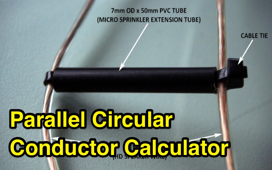 Design a parallel circular wire balanced transmission line with this online calculator. This calculator is a tool for designing balanced transmission lines with a specific desired characteristic impedance Zc and made of parallel circular conductors of a given diameter d.
 -
 An easy to build and extremely high performance antenna, works perfectly on all HF bands 3.5-28 MHz with some compromises, it is basically an half wave dipole for 40-80 meters, an LC circuit or trap 40 meters allows you to use a single radiating element.
 -
 BeaconSpot.uk provides an accurate, real-time picture of microwave and VHF/UHF beacons operating across Europe, alongside a worldwide listing of 6-meter beacons. The platform allows users to retrieve detailed data for individual beacons, facilitating in-depth analysis of signal characteristics and propagation paths. Interactive maps visualize beacon distribution by frequency band and display spot coverage for each station, offering a clear geographical overview of active beacons. The system integrates real-time DXCluster spots, sourced from contributors like Alain, ON4KST, and Pascal, F5LEN, and enables users to submit outgoing spots directly to the DXCluster. Beacon keepers can manage their beacon data, receive email alerts upon being spotted, and track their station's ODX (Outstanding DX) records. For every received spot, the distance to the beacon is automatically calculated and displayed, aiding propagation studies.
 -
 The article, "Using 75 Ohm CATV Coaxial Cable," details methods for employing readily available 75-ohm CATV hardline in standard 50-ohm amateur radio setups. It addresses the inherent impedance mismatch and practical considerations, such as connector compatibility, for hams seeking cost-effective, low-loss feedline solutions. The resource specifically contrasts common 50-ohm cables like RG-8, RG213, and _LMR-400_ with 75-ohm hardline, highlighting the latter's lower loss characteristics, particularly at VHF and UHF frequencies. It explores two primary approaches to manage the impedance difference: direct connection with an acceptable SWR compromise and precise impedance transformation. The direct connection method acknowledges that a perfect 1:1 SWR is not always critical, especially when using low-loss coax. For impedance transformation, the article explains the use of half-wavelength sections of coax to reflect the antenna's 50-ohm impedance back to the transmitter, noting its single-frequency effectiveness. It also briefly mentions transformer designs using toroid cores and a technique involving two 1/12 wavelength sections of feedline for broader bandwidth. The content further clarifies the concept of _velocity factor_ for calculating electrical versus physical cable lengths, providing a generic formula for precise length determination. It notes that while half-wave matching is practical for 10 meters and above, it can result in excessively long runs for lower bands like 160 meters, potentially adding **250 feet** of cable. The article also mentions achieving a usable bandwidth of 28.000 MHz up to at least **28.8 MHz** on 10 meters with specific transformation techniques.
 -
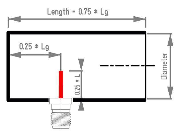 Aka Circular Waveguide Antenna. This online antenna calculator let you plan your cantenna for the desired frequency of operation, giving the Can diameter you have available.
 -
 This web article details the construction of a 4-meter band coaxial dipole antenna, designed for operation between **70.000 MHz and 70.500 MHz**. The resource provides a bill of materials and step-by-step assembly instructions for a half-wave dipole constructed from _RG-58_ coaxial cable. The design specifies a direct 50 ohm feedpoint impedance, eliminating the need for an external matching network. Construction photographs illustrate the stripping and soldering processes for the coaxial cable elements, ensuring proper electrical connection and physical integrity. The article includes specific dimensions for the radiating elements, derived from calculations for the 70 MHz band. The project outlines the physical dimensions required for resonance at 70 MHz, with the outer braid forming one half and the inner conductor forming the other. The feedline connection is directly to the coaxial dipole's center, maintaining a 50 ohm characteristic impedance. While the article does not present SWR plots or VNA sweeps, it focuses on the mechanical construction and dimensional accuracy for achieving a functional 4-meter dipole. The design is intended for fixed station use, with no specific mention of polarization or height above ground, but implies a standard horizontal orientation for dipole operation. DXZone Focus: Web Article | 4m Coaxial Dipole | Construction Guide | 50 ohm Feed
 -
 Inches and meters Javascript Wavelength Calculator allow to input a frequency in MHz and calculate wavelenght in several units considering also fractions of wavelenght and the velocity factor. Includes an usefull inch to meter converter
 -
 The program consists of tabbed pages for various antenna and transmission line calculation. You can compute the values for an inverted L network that will allow you to match the 50 ohm output of the radio, or you can compute the necessary length in the units of choice for a 5/8 wave vertical for 10 meter band.
 -
 On March 27, 2017, the FCC adopted final rules for the USA 630-meter band, detailed in Report and Order FCC 17-33, which required PLC coordination with the Utilities Telecom Council before amateur operations could commence. This resource documents the WD2XSH experimental group's activities, including authorized stations, band plans, and frequency assignments within the 465-515 KHz range, with many stations operating between 495-499 KHz and 501-510 KHz. The site also highlights the WRC-12 decision on February 14, 2012, which granted a new **7-kilohertz-wide** secondary allocation between _472-479 kHz_ for the Amateur Radio Service worldwide. The group's efforts included operating with a maximum ERP of **20 Watts** across 45 stations in the continental USA, Alaska, and Hawaii, using emission modes such as CW, PSK-31, FSK-31, and MSK-31. The site provides links to download FCC 17-33 in PDF and DOCx formats, and offers a station location map, a list of stations by callsign and frequency, and an archive of news updates. Reception reports for any 600-meter station are encouraged to help the amateur radio community understand propagation and repeatability on this challenging band.
 -
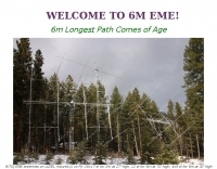 Making EME contacts on six meter band. An US Experience using a pair of 8 yagi arrays for the 50 Mhz.
 -
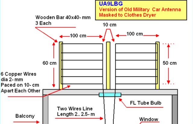 The antenna almost repeat the design of the Car Antenna however instead of aluminum tubes it was used copper wire in plastic insulation in diameter of 2- mm (12 AWG).
 -
 Constructing a multi-band fan dipole for HF operation presents unique challenges, as VE2XIP demonstrates through his 2012 project to replace an existing commercial antenna. He details the process of calculating wire lengths using the 468/frequency formula, emphasizing the critical importance of equal leg lengths for each dipole element. The author shares practical insights gained from building at ground level, noting how elevation impacts resonant frequency and SWR, particularly for lower and higher bands. VE2XIP's experience highlights the iterative nature of antenna tuning, starting with the lowest frequency band (80m) and working upwards. He provides a specific example of trimming calculations and offers a clever tip for accurate wire removal. The article also touches on the mechanical aspects, such as dowel spacing for wire support and the benefits of a pulley system for repeated raising and lowering during the tuning process. Field results showed significant performance gains over the previous Alpha-Delta DX LB Plus, with **20 dB over 9** signal reports on 80m compared to 57. The project cost around **$100** for hardware, proving a cost-effective alternative. The author also discovered a bonus 6m capability and achieved an inverted-V _obtuse angle_ of approximately 115 degrees, contributing to a surprisingly stealthy installation.
 -
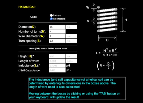 This online calculator will give as output the Inductance L of a coil, including the total lenght of the wire needed to wound the coil. As input, requires the Diameter, number of turns, wire diameter and turn spacing
 -
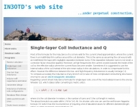 This calculator ask as input diameter, lenght turn and frequencu and will return L and Q
 -
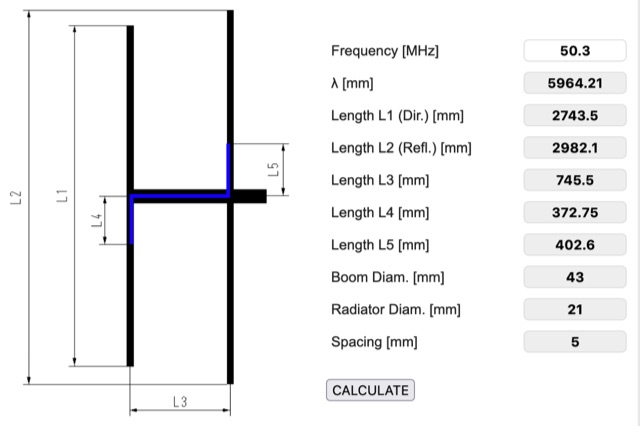 Online HB9CV antenna calculator, accept as input the desired resonating frequency and provides dimensions for spacing and length of each element, including boom and radiator diameter.
 -
 Sixty-meter repeaters typically use a 1 MHz frequency separation between input and output, while 2-meter repeaters commonly employ a **600 kHz** split and 70-centimeter repeaters use a **5 MHz** offset. This article details the fundamental technical principles of amateur voice repeaters, explaining how they extend VHF/UHF communication range by receiving on one frequency and simultaneously retransmitting on another. It covers essential components such as receivers, transmitters, filters, and antennas, often situated on elevated locations for optimal coverage. The resource delves into the critical challenge of _desensing_—where the repeater's strong transmit signal overpowers its own receiver—and the engineering solutions employed, including antenna separation and the use of high-Q cavity filters. It also explores various control and timing systems, from basic squelch activation to more sophisticated microcontroller-based boards that manage functions like voice identification, time-out timers, and fault protection. Different access methods are discussed, including open access, toneburst, CTCSS subtone, and DTMF, each offering distinct advantages for managing repeater usage and mitigating interference. Furthermore, the article examines repeater linking, both conventional RF methods and modern internet-based solutions, highlighting how linking expands coverage and promotes activity across multiple repeaters or bands. It introduces less common repeater types such as 'parrot' repeaters, which use a single frequency and digital voice recording, and linear translators, capable of relaying multiple signals and modes simultaneously across different bands, often found in amateur satellites.
 -
 A home made portable vertical antenna, that with a single 1/4 wave counterpoise wire is possible to achieve less than 1.5:1 SWR on 40, 30, and 20 meter bands. It is basically a center load, shortened ground plain vertical antenna.
 -
 Antenna may be made practically from any wire (strand, solid) having a reasonable diameter 0.5 2.0 mm (24- 12 AWG). Antenna may be installed at any balcony of 3 to 6 meter length.
 -
 Constructing a basic multimeter involves integrating a 0-1mA meter movement with various shunts and multipliers, selected via a switch, to create a versatile instrument capable of measuring DC volts, current, and resistance. The design outlines two main units: a primary unit handling six DC current ranges up to 1 amp and eight DC voltage ranges up to 1000 volts, alongside an internal battery for an ohms range up to 200,000 ohms. This approach allows for a practical, hands-on understanding of meter operation. An add-on unit further extends the multimeter's capabilities, incorporating a meter rectifier and switched series resistors to provide four AC voltage ranges up to 100 volts. Additional shunt and series resistors, designated Ra and Rb, are included to expand the instrument's range to 10A and 5kV, demonstrating how modular design can enhance functionality. When this add-on is in use, the main instrument is set to measure 1mA FSD, connecting via specific lugs. Component selection emphasizes precision, with 1% tolerance high stability resistors for series elements and Eureka resistance wire for shunts. The design specifies values calculated for a meter with 60 ohms internal resistance, noting that these would require modification for different meter characteristics. Experimental adjustment of shunt values is recommended to ensure accurate readings against a calibrated reference meter, reinforcing practical calibration techniques.
 -

-
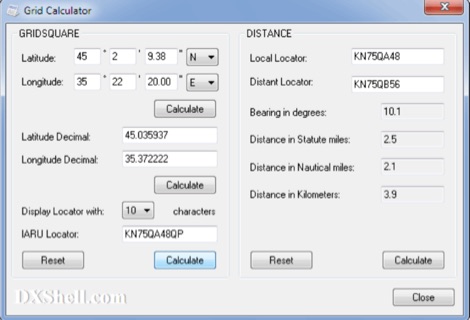 Grid Calculator allows you to calculate either a grid square locator or the latitude and longitude of a location. Grid Calculator can be used to calculate a Great Circle bearing and distance between two stations in statute miles, nautical miles, and kilometers.
 -
 Manufacturer of RF generators, attenuators, counters and LCR meters
 -
 A 0-30 MHz step attenuator, constructed from switchable Pi attenuation pads, provides a practical tool for evaluating receiver sensitivity and calibrating S-meters. The design utilizes readily available 5% tolerance resistors, with values derived from paralleled components to achieve specific attenuation steps. A schematic (Fig 1) illustrates the circuit, including PCB pad shielding, while a table details required and actual resistor values, along with percentage differences. Measurements of voltage input versus output at various frequencies are used to calculate dB attenuation, presented in a graph (Fig 4). The resource includes formulas for determining output voltage from a known input and a comprehensive 0-40 dB voltage multiplier table, which is crucial for precise signal level management. The project also references external attenuator calculators and equations for further study. Photos (1-3) provide visual guidance for the assembled unit, showing bottom, top, and front views. The project emphasizes the use of **Pi attenuation pads** and **receiver sensitivity** evaluation, offering a hands-on approach to RF signal management.
 -
 The Boone Area Radio Klub (BARK) serves Boone County, Iowa, as its local amateur radio club, actively welcoming visitors to its meetings and weekly ARES nets. The club maintains a 2-meter repeater on 146.850/250 MHz with a 114.8 Hz tone and a 440 MHz repeater on 443.9+ MHz, both situated at the Boone County Hospital, with a simplex fallback on 146.550 MHz for the 2-meter net. Additionally, BARK supports the Iowa 160-meter ARES net at 1.972.5 MHz, which operates at 9:30 PM on Sundays, featuring a rotating schedule of net controls including KNØR, KBØMPL, NØISU, KEØQEU, and KBØLPI. BARK conducts bimonthly license testing sessions on the second Saturday of even-numbered months, with specific dates like October 19, 2024, at the Hamboree, requiring a $15 fee and prior FCC Registration Number (FRN) acquisition. The club's activities are well-documented through numerous photo galleries from past Field Days (1998, 1999, 2008, 2010, 2013, 2017, 2018, 2019), JOTA events (2013), and special event stations (2010 B&SVRR&M). Members like KBØMPL (Margot Conard) have contributed educational PowerPoint presentations on topics such as "Fun with Handie Talkies," "HF Propagation," and "Digital Mode - FLDIGI - OLIVIA 8/500 - JT65 HF - BAND PLANS." The club's officers, as of May 2018, include WØFS (Clay Conard) as President, NØISU (Mitch Carroll) as Vice-President, and KBØLPI (Eric Sloan) as Treasurer/Secretary, guiding the club's operations and community engagement.
 -
 The Buddistick antenna, as demonstrated by KP4MD, effectively handles up to **250 watts** and provides coverage from 40 through 10 meters, with an optional coil extending operation to 80 and 60 meters. KP4MD's video presentation meticulously describes the antenna setup, emphasizing the critical role of the _shunting coil_ for achieving resonance on lower bands like 40 and 80 meters. This practical approach highlights how a compact antenna can deliver solid performance from a constrained location. SWR curve diagrams are included, clearly illustrating the impact of the shunting coil on the antenna's resonating frequency. These visual aids provide concrete evidence of the adjustments needed for optimal operation across different bands, particularly when space is at a premium. KP4MD's insights are particularly valuable for hams operating from apartments or other limited spaces, showcasing real-world results from a balcony installation.
 -
 The Baofeng UV-5R handheld transceiver, introduced around 2012, operates across the 2-meter (144-148 MHz) and 70-centimeter (420-450 MHz) amateur bands, offering dual-band receive and transmit capabilities. This review provides an early assessment of the radio's form factor, user interface, and general performance, noting its compact size and the inclusion of a **VFO/Memory mode** button for frequency management. The device supports both FM and narrow FM modes, with a reported power output of 4 watts on VHF and 3 watts on UHF, making it suitable for local simplex and repeater operations. Key features discussed include its 128-channel memory capacity, a built-in VOX function, and a **DTMF keypad** for tone dialing and repeater access. The review highlights the radio's ability to scan frequencies and memories, along with a dual-watch function allowing simultaneous monitoring of two frequencies. Battery life is addressed, with the standard 1800 mAh Li-ion pack providing several hours of operation depending on transmit usage. Initial impressions cover the radio's construction and the clarity of its LCD display, which shows both A and B band frequencies.
 -
 Basic magnetic loop antenna examples and loop aerials theory explained. This article inclued some interesting tricks on building magnetic loop antennas and an usefull excell sheet to help compute magneti loop antennas calculating power efficiency from 10 to 40 meters band
 -
 The Tri-pole antenna, a clever modification of a standard dipole, allows for dual-band operation by integrating a third element. This design effectively shortens the overall dipole length by 10 to 20 percent, simplifying antenna rotation and offering a compact footprint. KK4OBI's article delves into the operational principles, using a 6 and 10-meter Tri-pole as a primary example, and provides comprehensive instructions for constructing any Tri-pole antenna within the 6 to 15-meter range. Key to the Tri-pole's performance is its off-center feed, necessitating a common mode choke at the feed point for optimal tuning and reduced noise. The author outlines a methodical approach to determining element dimensions, starting with a vertical element frequency calculated as 0.47 times the sum of the desired upper and lower band frequencies. This calculation, along with K-values derived from trend lines, guides the initial lengths for the horizontal arms, demonstrating how a 10m-6m Tri-pole can achieve a total horizontal length 78% shorter than a conventional 10-meter dipole. Tuning and balancing are critical, with the article detailing adjustments to arm lengths and the vertical element to achieve balanced SWR values, as validated through 4NEC2 simulations. Radiation patterns are analyzed at various elevations, showing gains around 5.7 dBi and favorable take-off angles for DX contacts. Construction details specify aluminum tubing dimensions, U-bolts, and an SO-239 connector, emphasizing the importance of a ferrite-based choke for wideband operation.
 -
 A basic YAGI UDA online antenna calculator, accept as input frequency, number of elements, diameter of parasitic element and boom diameter. This online calculator will generate a basic design data including each element length and spacing.
 -
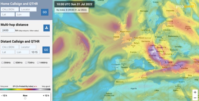 The map display allows you to select by locator, or clicking on the map, where you want to calculate the probability of Sporadic-E by building a combination EPI, Es Probability Index, based on factors using many of the known parameters which can effect Es. T
 -
 The simple balcony vertical HF antenna made with plastic fishing pole. Just along the pole I install copper wire in 7 meter length. Then was installed ATU. It was used home brew tuner. For each band was used one counterpoise in length 0.8 x lambda/4
 -
 DF0WD/DL4YHF's Longwave Overview details amateur radio operations on the 135.7 to 137.8 kHz segment in Germany. The author outlines the "inofficial" European band plan, specifying segments for QRSS, TX tests, beacons, conventional CW, and data modes. Early LF activities at DF0WD began with a 20-watt CW transmitter, later upgraded to a homemade linear transverter capable of 100 watts, driven by an Icom IC706 on 10.137 MHz. The station's antenna system includes a 200-meter wire, approximately 10 meters above ground, supported by football field light-masts. Despite its length, the antenna's efficiency is noted as very low due to the immense wavelength of about 2.2 km. The author's experience highlights the significant challenge of achieving effective radiated power (EIRP) on LF, estimating DF0WD's EIRP at around 80 milliwatts based on field strength measurements from PA0SE. DF0WD/DL4YHF has successfully worked numerous countries on 136 kHz CW, including DL, F, G, GI, GM, GU, GW, HB9, HB0, LX, OE, OH, OK, OM, ON, OZ, PA, and SM. The author also mentions ongoing efforts to log contacts with CT, EI, LA/LG, and to complete a two-way QSO with Italy, demonstrating persistent activity on this challenging band.
 -
 Enables Android users to operate various _miniVNA_ antenna analyzers via Bluetooth, USB, or Wi-Fi, providing a portable solution for RF measurements. The application supports full control over data acquisition, offering features like custom frequency range selection from 1 KHz to the VNA's full range, and automatic screen adaptation for diverse Android device resolutions. It facilitates intuitive, wizard-based calibration for both reflection and transmission modes, saving calibration data for different VNA types (Standard, Pro, Pro with Extender) to avoid repeated procedures. The software displays critical parameters such as SWR, |Z|, Return Loss, Phase, Rs, and |Xs| on 2-axis graphs or Smith charts, with multi-touch gestures for zoom and frequency shift. It includes a frequency generator mode with independent channels and attenuator control for the miniVNA Pro, along with a sweeper function. The cable data mode automatically calculates phase and loss, measures cable length from less than 1 meter to hundreds of meters, and includes a table of common coax cable velocity factors. An experimental X-tal mode measures resonance frequency, Rs, and Q. Data export options include CSV, ZPLOT, and S1P formats, with CSV import capability. The application also features an SM6ENG Audio mode for SWR tuning without visual reference and provides a miniVNA battery voltage indicator. It supports a wide frequency range, with the miniVNA Extender extending coverage up to **1500 MHz**. The application is compatible with Android version 2.2 and later, tested on devices like the _Galaxy TAB 7.7 P6800_.
 -
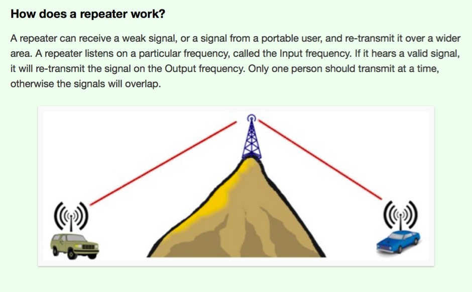 Amateur radio repeaters, often designated by an "R" number like _R6_ or _R5_, serve as crucial infrastructure for extending VHF/UHF communications range. This resource from Essex Ham explains the fundamental concept of a repeater, detailing how it receives on one frequency and simultaneously retransmits on another, typically with a 600 kHz offset for 2-meter repeaters. Understanding the input and output frequencies, along with the required CTCSS tone, is essential for successful access, ensuring your signal is processed and relayed across a wider service area. The article clarifies the importance of using the correct _CTCSS_ (Continuous Tone-Coded Squelch System) tone, often referred to as a sub-audible tone, to activate a specific repeater. It also touches upon the concept of _simplex_ operation versus repeater use, highlighting the benefits of repeaters for mobile and handheld transceivers. Proper operating procedures, such as listening before transmitting and keeping transmissions concise, are emphasized to maintain good amateur practice on shared repeater assets.
 -
 Determining the characteristic impedance (Z) of an unknown coaxial cable, a common challenge for many radio amateurs, can be resolved with a straightforward method. The impedance of a coaxial cable is derived from its inductance and capacitance, and importantly, these values are independent of the cable's length or the operating frequency. This means that measuring a random length of cable, such as 20 meters, provides sufficient data for calculation. The core of this technique involves an LC-meter to obtain the inductance (L) in microHenries (uH) and capacitance (C) in microFarads (uF). The impedance is then calculated using the formula Z = L/C. For instance, a measurement yielding L=1.2uH and C=450pF (0.00045 uF) results in an impedance of 51.6 Ohms, closely matching **RG-58** specifications. Similarly, a TV coaxial cable with L=1.8uH and C=320pF (0.00032 uF) calculates to 75 Ohms. While the accuracy of this method, depending on the LC-meter's tolerance, is approximately 10%, it proves sufficiently precise for practical determination of unknown coaxial cable impedance, as noted by Makis, SV1BSX, who credits Cliff, K7RR, for the formula's dissemination.
 -
 An inductance and capacitance meter, measuring range is from 0 to >0.1uF for capacitance and 0 to >10mH for inductance. A project by Phil Rice, VK3BHR
 -
 A 60-foot available space, for example, might necessitate a shortened multiband dipole array to cover 80, 40, and 15 meters effectively. This resource details the construction of such an antenna, combining full-size and coil-loaded dipoles on a single feedline. It addresses the common challenge of fitting multiple HF bands into restricted physical footprints, providing practical guidance for hams with smaller backyards or portable operations. The core of the offering is an interactive calculator that determines required loading coil inductance and dipole lengths for various amateur bands from 160m to 10m. Users input their available space, and the tool provides dimensions, coil turns, and an efficiency rating (Good or Fair) based on the antenna's electrical length relative to a quarter-wavelength. It also suggests suitable _PVC_ pipe diameters for coil forms. The article further illustrates a center feed-point assembly using an 18-inch section of 2-inch _PVC_ pipe, detailing eye-bolt spacing and coaxial connector installation. It emphasizes the importance of adequate spacing between parallel dipoles and offers customization options for the feed-point, including the addition of a _Balun_ for improved feedline isolation.
 -
 Microwaves101 provides an extensive repository of information covering fundamental principles of microwave design, targeting engineers and radio amateurs interested in the higher frequency spectrum. The site features a detailed _encyclopedia_ of microwave terms and concepts, alongside practical design considerations for various components and systems. It serves as a foundational reference for understanding RF propagation, transmission lines, and active/passive microwave circuits. The resource includes numerous calculators for impedance matching, filter design, and other critical RF parameters, facilitating hands-on project development. Discussions on **10 GHz** equipment and **24 GHz** projects highlight practical amateur radio applications, extending to operations up to 134 GHz. Content spans from basic theory to advanced topics like MMIC design and antenna characteristics, supporting both educational and practical endeavors in microwave technology.
 -
 Presents Wayne Kerr Electronics, a manufacturer specializing in precision component measurement products. The company offers a range of LCR meters, impedance analyzers, and transformer test systems designed for various applications in electronics manufacturing and research. Specific product lines include the 3260B Precision Magnetics Analyzer, which measures inductance, capacitance, and resistance with high accuracy, and the 6500B series of LCR meters, capable of testing components across a broad frequency range up to 120 MHz. The 3255B and 3265B series provide solutions for transformer and inductor testing, including turns ratio, leakage inductance, and inter-winding capacitance measurements. These instruments are utilized in quality control, component characterization, and production line testing, ensuring performance and reliability in electronic circuits. Wayne Kerr's offerings support engineers and technicians in verifying component specifications.
 -
 The Intercontinental Amateur Traffic Net (Intercon) operates daily on 14.300 MHz, providing a platform for emergency communications and facilitating third-party traffic among amateur radio operators. Established in 1960, the net aims to foster goodwill and friendly relations within the ham community. It operates from 0700 to 1200 Eastern Time, with a focus on monitoring emergency traffic while encouraging operators to maintain a distance of at least 5 kHz to avoid interference. All licensed General Class operators and above are welcome to check in, using standard phonetics for clarity. The net features rotating Net Control Station (NCS) operators every hour, ensuring a diverse range of voices and experiences. Operators are encouraged to provide relays and assist with emergency traffic when necessary. While there is currently no membership for non-NCS operators, opportunities exist for those interested in becoming NCS operators. The net emphasizes professionalism and courtesy, making it a valuable resource for both emergency communications and casual check-ins.
 -
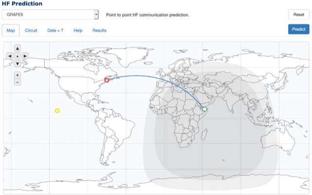 Online HF Communication prediction system provided by the Australian Governament Buerau of Metereology allow to predict usable frequency rage for radiocommunications between two stations allowing to specify frequency and date range. This tool allow calculation with different methods and algorithms
 -
 This air-core solenoid style RF inductor calculator calculates the inductance, wire size, number of turns, and other parameters for an air-core solenoid inductor used in radio frequency (RF) circuits, based on user input of frequency, desired inductance value, and physical dimensions.
 -
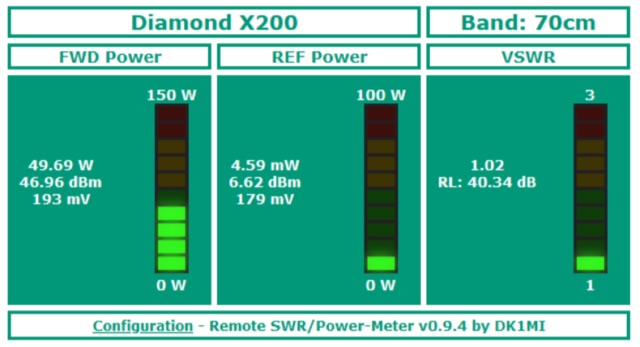 Remotely monitor the output power and SWR of your station via a web browser. WT32/ESP32 based project, combined with a directional coupler setup. It reads two voltages which are supplied by the directional couplers. From these, the respective power is calculated with the help of a calibration data table to be created by the user.
 -
 The antenna I built was inspired by a portable delta loop designed by Doug DeMaw, W1FB. Given that I constrained myself to a 50-foot roll of speak wire, I scaled my antenna for the 20M band. Using the formula, 1005 divided by the frequency in megahertz, I calculated a total length of 71 feet (21.6 meters) for the center of the 20M band.
 -
 Learn how to design and analyze a folded trifilar antenna for the 80-meter band. Based on a description from RAF antennas between 1940 and 1970, this article provides step-by-step guidance on modeling the antenna, calculating resonance frequency, adjusting dimensions, and verifying performance. Perfect for hams looking to improve their antenna setup for better transmission and reception on the 80M band.
 -
 Presents a detailed construction guide for a 9 dB, 70cm collinear antenna, utilizing readily available _RG58/U_ coaxial cable and PVC pipe for housing. The resource outlines the critical calculations for ½ wavelength sections at 444 MHz, incorporating the coaxial cable's velocity factor of 0.66, which yields a section length of 223 millimeters. It specifies the preparation and soldering of eight such half-wavelength sections, each cut to 231mm to allow for trimming, forming the core of the array. Further instructions detail the integration of a ¼ wave element (169mm #16 solid wire) at the top and a ¼ wave aluminum tube (160mm, 5/16 inch) at the bottom, crimped to the feed point's braid. The guide also addresses RF common mode current suppression by suggesting the use of _FT50-43_ toroids on the feedline. Final assembly steps cover mounting the antenna within ¾" PVC pipe using a wooden dowel, waterproofing connections, and initial SWR checks. The article also discusses scaling the design for different element counts and other VHF/UHF bands.
 -
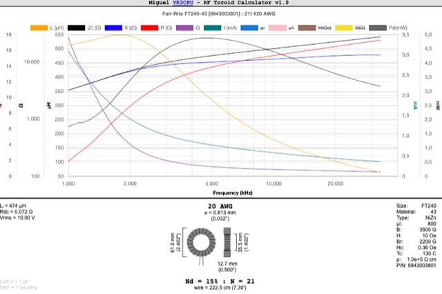 This RF Toroid Calculator provides graphical calculator used to determine the inductance and other parameters of ferrite and powdered-iron toroids. It simplifies the process of selecting the appropriate toroid for use in radio frequency (RF) circuits