Search results
Query: antenna rope
Links: 137 | Categories: 2
-
 Construct a compact, 20 meter rotatable dipole antenna of durable weather worthy components supported at a single point obviating the need for multiple supports and multiple support ropes crossing the yard.
 -
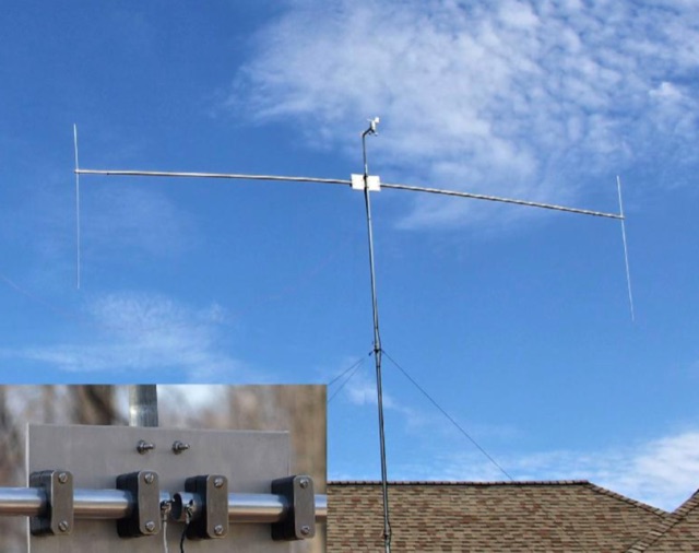
 A new, simple way to build the Eggbeater Antenna. This document introduces a new, simpler way to build the Eggbeater antenna. It also introduces a technically proper way to construct the Eggbeater antenna in order to achieve the best result.
 -
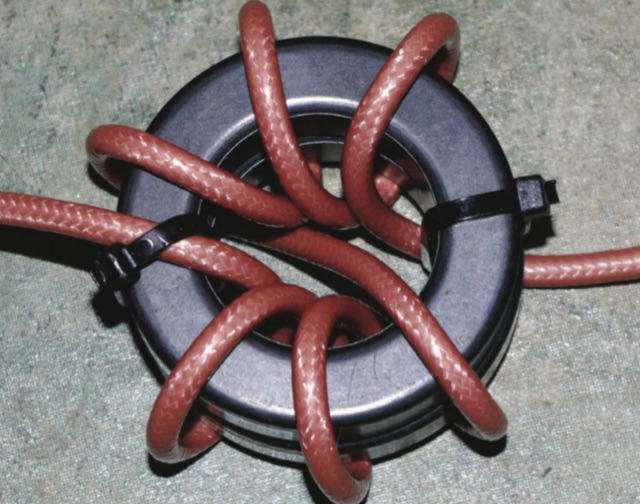 May 2015 Radcom Article on common-mode chokes that can be used for control cables, phone lines, but mostly on typical HF antenna systems. This article explain what common mode chokes does, why you meay need one, properties common mode chokes should have, how to build and measure performances.
 -
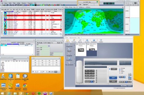 Operating a modern amateur radio station often involves integrating various software tools, and LogHX aims to provide a unified environment for Windows users. The software facilitates comprehensive QSO accounting, allowing operators to track contacts and manage both e-QSL and traditional paper QSL exchanges, including via QSL managers or direct methods. It also offers real-time QSO preview and integrates with popular callbook data for quick lookups. LogHX supports various logbook database searches and maintains statistics for numerous awards, a critical feature for serious DXers and contesters. The program handles logbook import and export in widely used formats such as _ADIF_ and _Cabrillo_, ensuring compatibility with other logging applications. Furthermore, it interoperates with Telnet clusters and third-party ham radio software, enhancing its utility in a networked shack environment. Key functionalities include antenna rotator control, editable macros for PSK, RTTY, CW, and SSB operations, and CAT control via _OmniRig_ or direct interfaces. Embedded modules like MMVari, MMTTY, and CWServer streamline digital mode operations, while its multi-window structure allows users to customize their screen layout, preserving valuable monitor space.
 -
 The NB6Zep Antenna, an electrically shortened 80-meter end-fed wire, addresses space constraints for low-band operation by integrating two loading coils into a 37-foot wire. This design, modeled with _EZNEC_, explores configurations like the quarter-wave sloper and inverted-L, with the latter providing a more vertical radiation pattern and practical backyard deployment. The resource details specific coil construction, recommending 21 uH coils made from _BW coil stock #3026_ or similar, and outlines wire segment lengths for optimal tuning. Performance analysis indicates a radiating efficiency of approximately 27% with good ground conductivity, resulting in a signal typically 3-4 dB down compared to a full-size quarter-wave vertical. The antenna exhibits a narrow bandwidth, around 50 kHz, due to its high Q, necessitating a tuner for broader band operation. Feedpoint impedance is low, with ground resistance playing a critical role in achieving a usable SWR. The article emphasizes the importance of an effective ground rod at the feedpoint for proper operation and tuning, suggesting an antenna analyzer for precise adjustments. It confirms the antenna's suitability for DX, citing successful contacts from Oregon to the East Coast and Hawaii on a 160-meter variant, making it a viable option for urban operators seeking low-angle radiation on 80 meters.
 -
 This is about Small Antenna types and their properties which can help choosing proper antenna for high-frequency wireless communications as: two-way radio, microwave short links, repeaters, radio beacons or wireless telemetry
 -
 A frame antenna for the 80 meters band, built to be folded and to be easy to be mounted and dismounted. This antenna is suitable for indoor and QRP use, bandwidth is just 10kHz and should be observed a proper distance while transmitting due to high voltage.
 -
 Frequencies and location of every meteo radiosonde launching centres in Europe. Equipments, antennas, history, SondeMonitor and BalloonTrack tutorials
 -
 Basic guidelines for proper placement of an amateur radio mobile antenna
 -
 The **TransWorld Antennas TW2010 Traveler HF Portable Vertical Antenna** assembly video provides a visual walkthrough for deploying this popular portable HF antenna. It details the step-by-step process, from unpacking components to final setup, which is crucial for operators preparing for field day operations or DXpeditions. The video focuses on practical aspects, showing how to connect the various elements and secure the antenna for optimal performance. Operators often seek clear assembly instructions for portable antennas like the TW2010 to ensure quick and correct deployment in diverse environments. This visual aid helps clarify potential ambiguities found in written manuals, illustrating the proper handling of the antenna's radial system and telescopic elements. The video serves as a valuable resource for those aiming to achieve efficient operation with the **TW2010 Traveler** in a portable setting. Understanding the assembly sequence can significantly reduce setup time and prevent common errors encountered during initial deployments.
 -
 The _Sci.Electronics FAQ: Repair: RFI/EMI Info_ document, authored by Daniel 9V1ZV, provides a detailed analysis of computer-generated RFI/EMI, focusing on its impact on radio reception. It identifies common RFI sources such as CPU clock rates (e.g., 4.77 MHz to 80 MHz), video card oscillators (e.g., 14.316 MHz), and even keyboard microprocessors, all of which generate square-wave harmonics across HF and L-VHF regions. The resource outlines a systematic procedure for pinpointing RFI origins, including disconnecting peripherals and using a portable AM/SW receiver with a ferrite rod antenna to localize strong interference sources. The document categorizes RFI mitigation into shielding, filtering, and design problems, offering practical solutions for each. It recommends applying conductive sprays like _EMI-LAC_ or _EMV-LACK_ to plastic casings of radios, monitors, and CPUs to create effective Faraday cages, emphasizing proper grounding and avoiding short circuits. For filtering, the guide suggests using line filters, ferrite beads, and toroids on power and data lines, and small value capacitors (e.g., 0.01 uF for serial/parallel, 100 pF for video) to shunt RFI to ground. It also discusses the use of bandpass, high-pass, low-pass, and notch filters on the receiver front-end or antenna feed to combat specific in-band noise.
 -
 KB9AMG's Top WSPR Spots presents a focused online tool for monitoring **2-way WSPR reports**, specifically detailing propagation data from February 2026 through March 2026. This resource aggregates _WSPRnet_ data, allowing radio amateurs to observe weak signal propagation conditions across various bands. The interface is straightforward, presenting callsigns, frequencies, signal-to-noise ratios, and distances for each reported contact, which is crucial for understanding current band openings and signal paths. The utility of this WSPR spotter lies in its ability to quickly visualize global propagation. Users can identify active stations and assess signal viability over long distances, with reports often showing contacts spanning thousands of kilometers. For instance, a typical WSPR report might indicate a signal from Europe reaching North America with a _SNR_ of -25 dB, demonstrating effective low-power communication. This data is invaluable for planning DX operations or evaluating antenna performance under actual propagation conditions.
 -
 Operating a ham station often involves encountering radio frequency interference (RFI), RF feedback, or RF burns, which are frequently misattributed to poor equipment grounding. This resource meticulously dissects these assumptions, asserting that RF grounds on the operating desk often merely mask more significant system flaws. It identifies five primary causes for RF problems, including antenna system design flaws, proximity of the antenna to the operating position, DC power supply ground loops, equipment design defects, and poorly installed connectors or defective cables. The content emphasizes that issues like "hot cabinets" or changes in SWR when connecting a ground indicate substantial RF flowing over wiring or cabinets, a phenomenon known as common-mode current. The article provides detailed explanations of common-mode current generation, particularly from single-wire fed antennas like longwires, random wires, and OCF dipoles, which inherently present high levels of RF in the shack. It also illustrates how vertical antennas, lacking a perfect ground system, can excite feed lines with significant common-mode current. Through simulations, the author demonstrates how a dipole without a proper _balun_ can cause RF problems at the operating desk, showing current patterns and voltage distributions on feed line shields. The discussion extends to the proper application of _RF isolators_ and _ferrite beads_, clarifying their role in modifying common-mode impedance on cable shields and cautioning against their use as a band-aid for fundamental system defects. The resource advocates for correcting the actual source of RF problems, such as antenna system issues or poor connector mounting, rather than relying on internal shack grounding or isolators. It highlights that properly functioning two-conductor feed lines, like coaxial or open-wire lines, should result in minimal RF levels at the operating position, even without a desk RF ground. The author shares personal experience, noting that his stations since the late 1970s have operated without RF grounds at the desks, relying instead on proper antenna system design and feed line integrity.
 -
 The TransWorld Antennas TW4040 The Adventurer Monobander™ is a portable HF antenna designed for rapid deployment in field operations, including **SOTA** and **POTA** activations. This manual details the antenna's assembly, tuning procedures, and operational guidelines for optimal performance on the 40-meter band. It outlines the specific components, such as the telescoping whip and base unit, required for proper setup. Instructions cover mast erection, radial wire deployment, and impedance matching to achieve a low **VSWR** across the designated frequency segment. The document also provides guidance on antenna orientation and environmental considerations for portable use. It specifies the antenna's power handling capabilities and physical dimensions when fully deployed and collapsed for transport.
 -
 A distributed capacity coaxial dipole antenna. The antenna is very broadbanded with a very flat swr on all band when setup of the antenna is done at the proper lenght and height.
 -
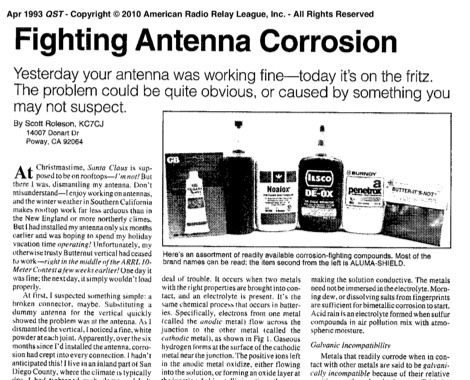 How to make proper maintenance of your antenna. Fighting Antenna Corrosion is a QST article published in 1993 that helps on antenna maintenance works
 -
 How to build Fan-Dipoles by DK7ZB. Experiences with various band combinations. Not all combinations are working properly. If the frequencies are to close together the impedances will lead to a very bad SWR. This happens with the bands 10-12-15m or 15-17-20m.
 -
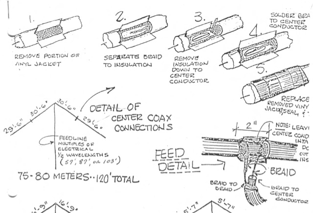
 This web article details the construction of a 4-meter band coaxial dipole antenna, designed for operation between **70.000 MHz and 70.500 MHz**. The resource provides a bill of materials and step-by-step assembly instructions for a half-wave dipole constructed from _RG-58_ coaxial cable. The design specifies a direct 50 ohm feedpoint impedance, eliminating the need for an external matching network. Construction photographs illustrate the stripping and soldering processes for the coaxial cable elements, ensuring proper electrical connection and physical integrity. The article includes specific dimensions for the radiating elements, derived from calculations for the 70 MHz band. The project outlines the physical dimensions required for resonance at 70 MHz, with the outer braid forming one half and the inner conductor forming the other. The feedline connection is directly to the coaxial dipole's center, maintaining a 50 ohm characteristic impedance. While the article does not present SWR plots or VNA sweeps, it focuses on the mechanical construction and dimensional accuracy for achieving a functional 4-meter dipole. The design is intended for fixed station use, with no specific mention of polarization or height above ground, but implies a standard horizontal orientation for dipole operation. DXZone Focus: Web Article | 4m Coaxial Dipole | Construction Guide | 50 ohm Feed
 -
 How to setup a proper antenna feed line with a particular attention to RFI by K0GKJ
 -
 Mobile RFI, often manifesting as persistent noise in the receiver even with the antenna disconnected, frequently originates from the vehicle's power supply system. This guide details systematic troubleshooting steps, beginning with isolating the radio from the car's 12-volt supply to confirm the power system as the noise source. It emphasizes the critical importance of drawing power directly from the battery using **heavy gauge wire**, bypassing the fuse block to leverage the battery's natural capacitance for RFI suppression and ensuring a solid RF ground. Proper routing of power lines through the firewall is also covered, advocating for dedicated grommeted holes to prevent inductive coupling from other wiring harnesses. The article stresses the necessity of fusing both positive and negative leads from the battery, a crucial safety measure to prevent damage to the rig and mitigate high-current risks should the battery's engine block ground become compromised during service. Addressing **alternator whine**, a common high-pitched noise that varies with engine speed, the resource suggests checking battery connections and the alternator-to-battery harness for looseness or corrosion. It also mentions the utility of adding an external RF noise suppression capacitor in parallel with the alternator's internal capacitor for enhanced filtering, and the effectiveness of commercially available in-line power supply filters.
 -
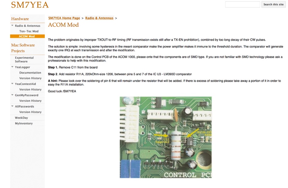 The problem originates by improper TXOUT-to-RF timing (RF transmission exists still after a TX-EN prohibition), combined by too long decay of their CW pulses.
 -
 K1JJ presents a compilation of insights regarding vertical radial ground systems, specifically applied to 160m vertical arrays. The resource details 19 distinct observations and recommendations, emphasizing that ground radials primarily reduce ground losses rather than influencing pattern formation. It explains that RF current flows inefficiently through average soil, necessitating copper radials to create a low-resistance path back to the antenna base. The content suggests that **50-60 radials** are generally sufficient to achieve optimal efficiency, with diminishing returns beyond that number, and that radials should be laid on the surface for best performance. The discussion also addresses practical aspects such as wire gauge, installation techniques using 'U' shaped staples, and methods for connecting radials in multi-element arrays. It highlights the importance of radial length, stating that 1/4 wave radials are a crucial minimum, and that for 160m, radials should be at least _100 feet_ long. The resource critically examines the efficacy of elevated radials versus ground radials, noting that while a few elevated radials may suffice for VHF, HF applications, particularly on 160m, require extensive ground radial systems to efficiently collect RF currents in the near field. It also touches on the impact of radial systems on parasitic elements and the significance of symmetrical radial patterns for minimizing losses. Further practical advice includes wire type recommendations, proper soldering and weatherproofing techniques for radial connections, and considerations for integrating steel towers into the ground system. The author shares personal experience with installing 60 quarter-wave and half-wave radials under each of three in-line verticals, expressing satisfaction with the results.
 -
 Synthetic guy ropes and accessories for antenna support systems
 -
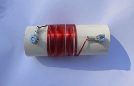 How to home made antenna traps with material you can easily find, and how to properly tune it.
 -
 1500 watts PEP SSB is the power handling capability of the MFJ-989C HF Antenna Tuner, a popular choice among amateur radio operators. Users have shared a wide range of experiences, with some praising its durability and performance over decades of use, while others criticize its build quality and accuracy. The tuner features a built-in dummy load, SWR-wattmeter, and a balun for balanced line feeders, making it versatile for various antenna setups. However, discrepancies in RF power readings and SWR measurements have been noted, with some users finding the dual scale meter to be off by about 20% compared to a Bird wattmeter. Long-term users report that the MFJ-989C performs well with proper antenna setups, but caution against tuning at high power without initial adjustments at lower power levels. Some have experienced issues such as arcing when exceeding 400 watts, while others have had no problems even at higher power levels. The roller inductor and capacitors are functional, though some users have had to perform maintenance like tightening screws or cleaning components to ensure reliable operation. Despite mixed reviews, the MFJ-989C remains in production, suggesting continued demand. It's a tuner that requires careful handling and possibly some DIY fixes to achieve optimal performance.
 -
 Relevance of a proper ground systems on short HF vertical antennas, with an analysis on a vertical antenna for 160 meter band
 -
 Installing a mobile rig in a vehicle requires careful planning and execution to ensure optimal performance and safety. The process begins with selecting the right equipment, such as the ICOM IC706MKII for low bands and the ALINCO DR-610 for VHF/UHF operations. Proper mounting is crucial; both radios are strategically placed under the back seat of the Silverado, allowing for a clean installation while maintaining passenger comfort. The Hustler antenna, equipped with various resonators, ensures coverage across multiple bands, while the LDG automatic antenna tuner fine-tunes the match for efficient operation. A remote head for the tuner enhances accessibility, making adjustments easier while driving. Each step of the installation is documented to provide insights and tips for fellow operators looking to enhance their mobile setup. The experience shared here reflects practical knowledge gained through hands-on work, aiming to inspire others in the ham community to undertake similar projects.
 -
 9M6MU Alfons details his family's efforts to establish an independent, self-sufficient home at Eagle Plateau in Borneo, a 50-acre highland property. The resource highlights their integration of **solar photovoltaic panels** for power generation, alongside managing water supplies, organic gardens, and fruit trees. It covers the practical challenges and rewards of living off-grid, including maintaining power generators and addressing infrastructure needs, all while pursuing the hobby of amateur radio. The narrative emphasizes a holistic approach to healthy living and nature conservation, reflecting the family's aspirations for an ideal ham world. Alfons and his XYL Doris share their experiences in building shelter and antenna farms, showcasing their dedication to independence and sustainable practices away from the conventional grid. The site also references the Hillview Gardens Amateur Radio Club, suggesting community involvement.
 -
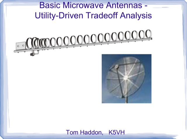 Utility-Driven Tradeoff Analysis, if you want to geto on the microwave bands , you will have to choose the proper antenna for your operating conditions. How to decide is not always easy, and you may also decide to build your own antenna.
 -
 HA8DU European manufacturer of quality amateur radio antenna tuners for HF Bands, from 10 meter to 160 meters band. Products includes manual and automatic antenna tuners, power handling till 3.5 KW. HA8DU produce even custom made variable capacitors and rotary switches.
 -
 DX Maps provides a specialized map printing service, focusing on amateur radio applications such as world prefix maps and custom great circle projections. The platform allows radio operators to visualize propagation paths and DX entities relevant to their QTH and operational goals. This service supports the creation of high-quality, large-format maps tailored for shack display or operational planning. The service facilitates the generation of personalized maps, which can include specific callsign locations, beam headings, and other critical amateur radio data points. Users can specify parameters to create maps that aid in understanding global propagation conditions and optimizing antenna aiming for long-distance contacts. The UK-based operation ensures a localized service for European hams, with international shipping options available. DX Maps also offers QSL card printing, complementing its mapping services.
 -
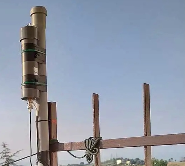 Notes on how to properly install a Mini Whip receiving antenna in an noisy urban environment.
 -
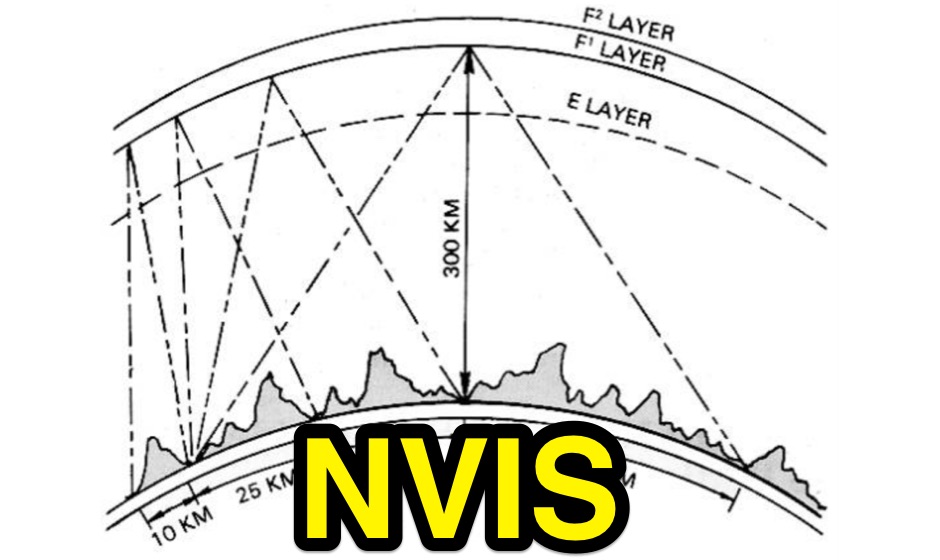 Operating NVIS mode, understanding operation frequencies, choosing the proper antenna to operate with the Near Vertical Incidence Skywave propagation
 -
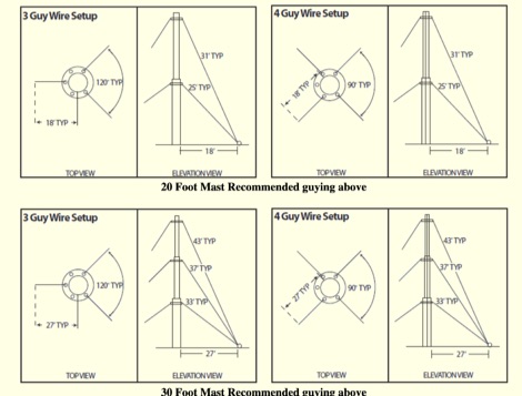 Article based on ROHN engineering specification that will guide on proper guying heights and guy lengths when guying ham radio antenna masts. It will help you determine ahead of time the proper length of guy wires and the distance from the base of the mast to the anchor points
 -
 This DIY vertical multi-band Windom antenna offers a practical and effective solution for amateur radio enthusiasts seeking a versatile and compact antenna for HF communications. Its simplicity of construction, multi-band capability, and favorable performance make it a valuable addition to any radio shack. The article provides detailed instructions on constructing the antenna and balun, along with diagrams and component specifications. Field tests demonstrated successful contacts with stations across Europe and North America on 14, 18, and 28 MHz. The antenna exhibited comparable performance to a W3DZZ dipole and outperformed a Cobweb antenna on 18 MHz. Low noise levels were observed, effectively suppressing background noise.
 -
 The resource, "Conventional Use of Transmission Line," meticulously details the operational principles of transmission lines, emphasizing the Transverse Electromagnetic (TEM) mode of energy transfer. It clarifies that for a line to function purely as a transmission line, all currents must be confined internally, with external fields ideally zero. The discussion differentiates between balanced and unbalanced lines, asserting that while both require equal and opposite currents within the conductors, the key distinction lies in the voltage relationship of each conductor to the surrounding environment. It highlights that a good antenna pattern does not inherently confirm proper feeder balance, and that common-mode currents can lead to RF in the shack and increased noise levels, even without pattern distortion. The article further explains that a transmission line can become a radiating conductor if energy is applied in a non-TEM mode, leading to common-mode issues. It cites classic texts like Jordan and Balmain's "_Electromagnetic Waves and Radiating Systems_" and Kraus's "_Antennas_" to support its definitions of TEM mode operation. The content also explores non-transmission line applications of parallel or concentric conductors, such as _coaxial dipoles_ and _folded dipoles_, which intentionally operate in non-TEM modes for antenna functionality. The author, _W8JI_, stresses that simply measuring equal currents is insufficient to confirm a balanced feeder; phase and voltage balance to ground are equally critical.
 -
 TIM-CO, an authorized distributor, offers a range of electronic components crucial for various applications, including amateur radio station builds. Their inventory focuses on **connectors**, both commercial and military-grade, which are essential for robust and reliable interconnections in radio equipment and antenna systems. This includes a variety of types suitable for RF applications, ensuring signal integrity. Beyond connectors, TIM-CO provides passive and electromechanical components, fundamental building blocks for any radio circuit or control system. These components are vital for constructing filters, impedance matching networks, and power distribution systems within a shack. Their selection supports both new construction and repair of existing gear. Additionally, the company supplies **RF-coax cable assemblies**, pre-fabricated solutions that save time and ensure proper termination for feedlines and inter-component connections. These assemblies are critical for minimizing signal loss and maintaining impedance matching from the transceiver to the antenna.
 -
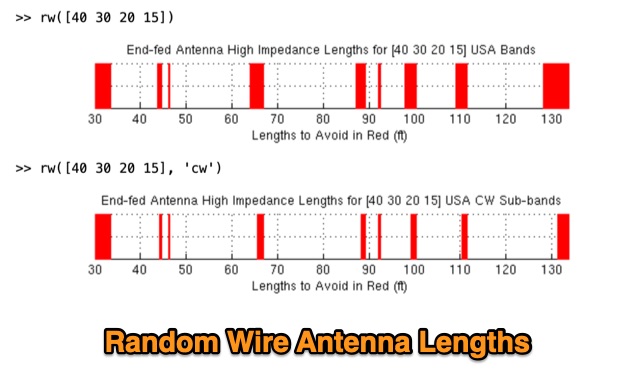 When on the trail, at Field Day, or whenever a good antenna is unavailable, a random wire can save the day, but it is important to understand its properties.
 -
 Make them simple then Make them work. The LAZY H antenna is a general type of antenna that is in the curtain array family. By placing two 1 wavelength dipoles in a plane that is at right angles to the direction of maximum radiation and keeping the proper in-phase current condition to each element, you can achieve a high gain bi-directional antenna.
 -
 High Speed Multimedia (HSMM) radio, as introduced by John Champa, K8OCL, represents a significant advancement in amateur radio's digital capabilities, moving beyond traditional keyboard modes like packet radio. This initiative, driven by ARRL's Technology Task Force, focuses on developing high-speed digital radio networks capable of up to 20 megabits per second. HSMM primarily facilitates digital voice (DV) and digital video (ADV), enabling real-time video transmission from emergency scenes to an EOC without expensive ATV gear, often requiring only a laptop, a PCMCIA card, a digital camera, and a small antenna. The working group's initial efforts concentrate on cultivating microwave skills within the amateur community to build and support portable and fixed high-speed radio-based local networking, or **RLANs**. These networks prove invaluable for RACES and ARES organizations, as well as homeland security and other emergency communications. Field Day exercises and simulated emergency tests (SETs) are encouraged to hone skills in rapid site surveys and deploying broadband HSMM microwave radio networks, with examples like linking Field Day logging stations or antenna test results at the Midwest VHF-UHF Society Picnic 2003. Getting started with HSMM often involves adapting off-the-shelf **IEEE 802.11** (WiFi) equipment to comply with amateur radio regulations, typically operating in the 2.4 GHz ISM bands. While consumer WiFi gear has range limitations under Part 15 rules, proper setup under amateur regulations can extend coverage significantly, with test networks like the Hinternet achieving 5-15 mile ranges at 54 M bit/s using small mast-mounted dish antennas. Careful selection of equipment with external antenna ports, high transmit power, and low receive sensitivity is crucial, along with using low-loss coaxial cable like LMR-400 for optimal performance at these frequencies.
 -
 DF0WD/DL4YHF's Longwave Overview details amateur radio operations on the 135.7 to 137.8 kHz segment in Germany. The author outlines the "inofficial" European band plan, specifying segments for QRSS, TX tests, beacons, conventional CW, and data modes. Early LF activities at DF0WD began with a 20-watt CW transmitter, later upgraded to a homemade linear transverter capable of 100 watts, driven by an Icom IC706 on 10.137 MHz. The station's antenna system includes a 200-meter wire, approximately 10 meters above ground, supported by football field light-masts. Despite its length, the antenna's efficiency is noted as very low due to the immense wavelength of about 2.2 km. The author's experience highlights the significant challenge of achieving effective radiated power (EIRP) on LF, estimating DF0WD's EIRP at around 80 milliwatts based on field strength measurements from PA0SE. DF0WD/DL4YHF has successfully worked numerous countries on 136 kHz CW, including DL, F, G, GI, GM, GU, GW, HB9, HB0, LX, OE, OH, OK, OM, ON, OZ, PA, and SM. The author also mentions ongoing efforts to log contacts with CT, EI, LA/LG, and to complete a two-way QSO with Italy, demonstrating persistent activity on this challenging band.
 -
 The BikeLoop antenna project details the construction of a double magnetic loop antenna optimized for VLF frequencies, specifically around 136 kHz. This innovative design incorporates two orthogonal loops, which significantly enhance reception capabilities. Key construction hints include utilizing lightweight bicycle rims for the antenna structure, making it easy to transport and set up in various locations. The document provides valuable mathematical and electrical insights into the antenna's performance, alongside practical reception tests conducted in the Italian Alps, showcasing its effectiveness in capturing various VLF signals, including Sferics and FSK transmissions. Proper setup is crucial for optimal performance. The project emphasizes the importance of grounding and avoiding interference from nearby electrical sources. The reception tests revealed the antenna's ability to capture a range of signals, demonstrating its practical application for enthusiasts interested in VLF reception and antenna experimentation. Overall, the BikeLoop serves as an excellent starting point for those looking to explore the world of VLF frequencies and enhance their antenna-building skills.
 -
 The Linked Dipole is a multiband antenna designed for 80/60/40/30/20m bands, optimized for the (tr)uSDX low bands configuration. It incorporates a 1:1 Balun to prevent common mode currents, ensuring balanced operation with coaxial cable. The Balun, wound on an FT140-43 core, achieves 37-40dB attenuation. The design includes a 3D-printable housing for compactness and waterproofing, with labeled link insulators for ease of use. Wire lengths were meticulously adjusted for optimal performance with a 7m pole and 3m rope extension, ensuring the antenna's ends are off the ground for improved behavior. The project includes downloadable printables for DIY construction.
 -
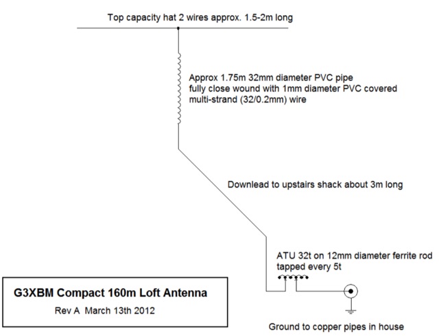 This is a very small vertical 160m antenna that fits in the loft of even my small house. It was built as a way of getting a signal out on 160m for local AM contacts, but the local noise level was far too high to allow it to be used at night for this purpose. However, on WSPR it did a pretty good job with WSPR spots from a very long way across Europe being received when running 2.5W out.
 -
 Discovering a solution for limited space, the inverted L HF antenna emerges as a stellar performer. Half the size of a dipole, it ensures optimal installation in restricted areas, maintaining superb transmission (TX) and reception (RX) characteristics. Spectrum Communications' multi-band version, featuring traps, proves even more space-friendly without compromising performance. A fiberglass pole offers sturdy support, while proper grounding, an RF choke, and occasional tuning contribute to a high-performing and reliable antenna system.
 -
 German antenna parts dealer, provides antenna element holders, element clamps for yagi antennas, junction boxes, aluminium plates and rods. Offers also Rope tensioners, plugs and adapters and any additional part you need when you want to make your own antenna.
 -
 Listen to online WebSDR located in Andorra Europe. Four receivers on 60m, 20m, 40m, and 80m, connected to a dipole antenna direction East/West
 -
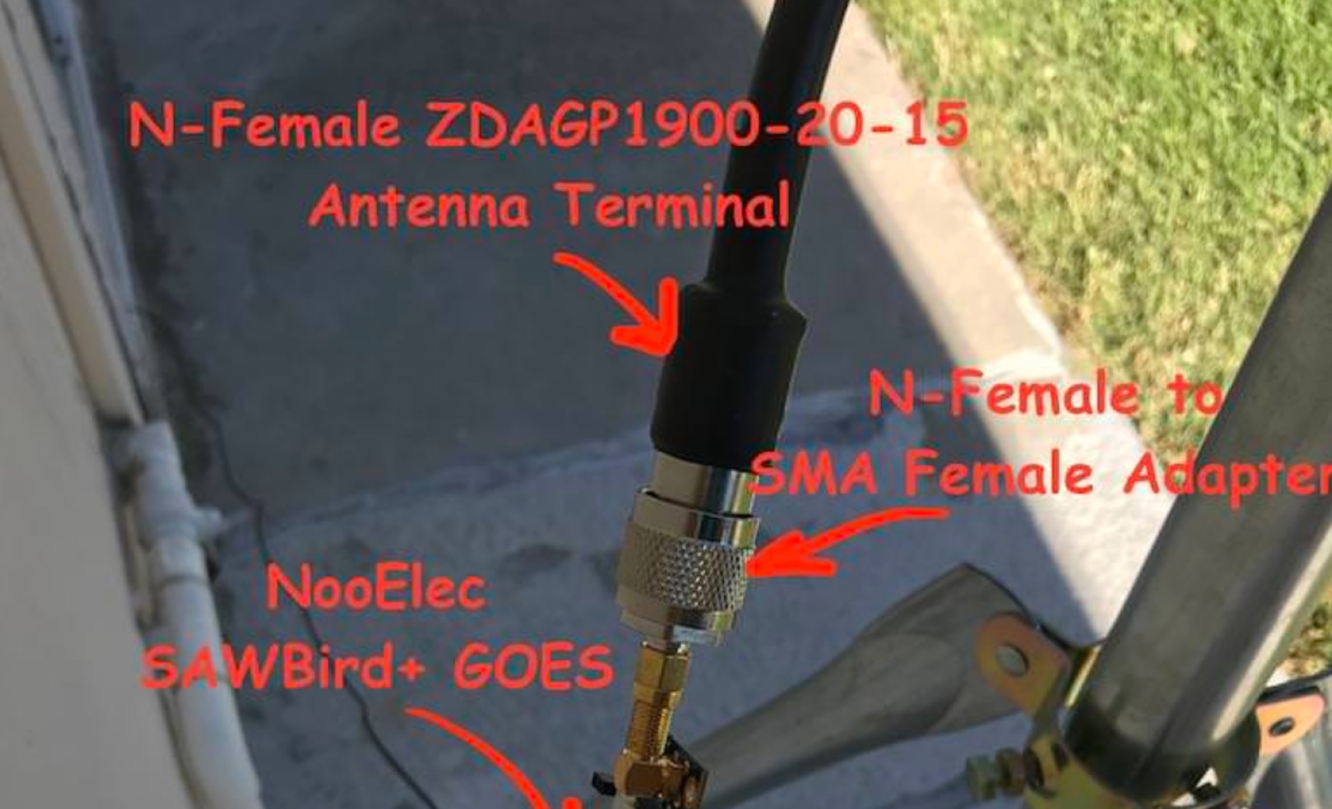 Receiving **GOES-16** and **GOES-17** weather satellite imagery requires a specific hardware and software configuration, detailed in this practical guide. The author outlines the necessary components, including a Raspberry Pi, an RTL-SDR dongle, a suitable LNA with SAW filter for 1.69 GHz, and a parabolic grid antenna. This setup enables direct reception of high-resolution weather data, a fascinating aspect of amateur radio satellite operations. The installation process begins with preparing the Raspberry Pi, followed by updating the system and installing essential dependencies like `git`, `build-essential`, and `cmake`. A critical step involves compiling and installing `librtlsdr` from source, ensuring proper driver setup and blacklisting conflicting DVB drivers. The guide then walks through testing the RTL-SDR dongle to confirm device recognition and troubleshoot common issues like USB power or driver installation problems. Finally, the instructions cover cloning and building `goestools`, a software suite essential for processing the satellite signals. This compilation, while time-consuming on a Raspberry Pi, is crucial for decoding the raw data into usable imagery. The guide concludes with the initial steps for creating the `goesrecv.conf` configuration file, preparing the system for active satellite reception.
 -
 The video showcases the setup of a 300 MHz oscillator, a 100W radiofrequency amplifier, and a dipole antenna for transmitting radio waves, leading to the fluorescence of a nearby light bulb. It demonstrates the presence of standing waves on the dipole antenna and how intensity varies along its length. Additionally, the usage of a copper pipe as a receiving antenna is explored, showing changes in intensity depending on alignment and proximity to the transmitter. Finally, a B field antenna sensitive to magnetic fields is introduced, revealing brightness variations in different orientations. The video offers insightful observations on radio wave transmission and reception phenomena.
 -
 This blog post details the construction and usage of a 4:1 current balun, using two FT240-31 ferrite cores and 12 bifilar turns. It clarifies common misconceptions about using 4:1 baluns with G5RV antennas and ladder-line to coaxial cable connections. M0PZT emphasizes the importance of proper measurements and the limitations of internal baluns in manual antenna tuners. Detailed instructions and considerations for winding and deploying the balun are provided, along with advice on choosing suitable cores and wire for various power levels and frequency ranges.