Search results
Query: coaxial
Links: 222 | Categories: 7
Categories
-
 RF Choke to prevent hf currents on the feedline. This Magnetic Longwire Balun (MLB) makes it possible to efficiently use a coaxial lead-in cable with all forms of longwires, T-forms or other types of wire antennas, without the need for an antenna tuner.
 -
 The Moxon Rectangle is growing in popularity as a compact 2-element array that approaches a full-size 2-element in gain but with a far superior front-to-back ratio and a direct match for the standard 50-Ohm coaxial cable.
 -
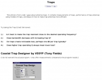 Testing and comparison of traps and trap antennas
 -
 A base station antenna you can easily build for 146,220 or 440 MHz, with performance similar to a J-pole but smaller and less obstrusive
 -
 The page describes the construction of a simple omnidirectional, vertically-polarised dipole antenna for two metres using coaxial cable. It can be used indoors or outdoors, with no extravagant gain claims. The project is low-cost and can be completed in about 20 minutes.
 -
 Constructing a Lindenblad antenna for 137MHz NOAA satellite reception involves specific design considerations for optimal performance. The resource details the use of 4mm galvanised steel fencing wire, 300-ohm television ribbon cable, and wood/plastic components for the antenna structure. Key dimensions for a 137.58MHz-resonant antenna are provided, derived from the ARRL Satellite Handbook, specifying s, l, w, and d as 42, 926, 893, and 654mm respectively. The antenna is designed for Right Hand Circularly Polarised (RHCP) signals, requiring the four folded dipole elements to be tilted clockwise by 30 degrees. A significant aspect covered is impedance matching between the antenna's 75-ohm impedance and a typical 50-ohm receiver input. A twelfth-wave matching transformer, constructed from 117mm sections of 50-ohm RG-58 and 75-ohm RG-59 coax with a 0.66 velocity factor, is described. The article also addresses coaxial cable and connector selection, recommending 75-ohm Type-N connectors for RG-6 cable in professional setups and F56/F59 connectors for general use, while strongly advising against PL-259/SO-259 connectors for VHF. Strategies for mitigating Radio Frequency Interference (RFI) are discussed, including antenna placement to shield from local TV transmitters and the use of commercial or DIY band-pass filters, such as cavity resonators or helical notch filters, along with ferrite chokes on coaxial cables. Antenna orientation is explored, noting the Lindenblad's 'cone of silence' directly overhead and its maximized sensitivity towards the horizon. An experimental vertical tilt of 90 degrees is presented as a method to improve overhead reception and reduce interference from strong horizontal signals, particularly relevant in high RFI environments like the Siding Spring Observatory site.
 -
 This Magnetic Longwire Balun (MLB) makes it possible to efficiently use a coaxial lead-in cable with all forms of longwires, T-forms or other types of wire antennas, without the need for an antenna tuner.
 -
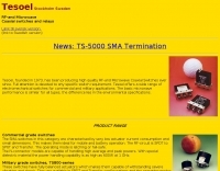
 Manufacturers and distributors of coaxial surge protectors, coaxial switches, insultators, HF fixed wire antennas
 -
 This resource details the computer-optimized design of the _ZS6BKW_ multiband dipole, an evolution of the classic _G5RV_ antenna. It begins by referencing the original 1958 RSGB Bulletin article by Louis Varney G5RV, explaining the operational principles of the G5RV's flat-top and open-wire feedline on 20m and 40m, noting its impedance transformation characteristics for valve amplifiers of that era. The article then transitions to the rationale for optimizing the design for contemporary solid-state transceivers requiring a 50 Ohm match. The core of the project involves using computer modeling to determine optimal lengths for the flat-top and matching section, aiming for a VSWR of less than 2:1 on multiple HF bands. It discusses the process of calculating feedpoint impedance based on antenna length and frequency, referencing professional literature from Professor R.W.P. King at Harvard University. The analysis also considers the characteristic impedance (Z(O)) of the open-wire line, identifying a broad peak of adequate values between 275 and 400 Ohms. Specific design parameters for the improved ZS6BKW are presented, including a shorter flat-top and a longer matching section compared to the original G5RV, with a velocity factor of 0.85 for the 300 Ohm tape. The article confirms acceptable matches on 7, 14, 18, 24, and 28 MHz bands when erected horizontally at 13m, and also discusses performance in an inverted-V configuration, noting frequency shifts. The author, Brian Austin ZS6BKW, emphasizes the antenna's suitability for modern 50 Ohm coaxial cable without a balun.
 -
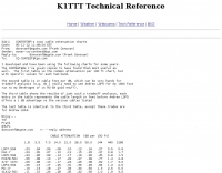
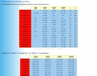 A table with Loss in DB/100m , Max power in Watts, Diameter in mm , Velocity factor (VF) expecially in VHF UHF and Microwave
 -
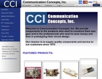 Communication Concepts, Inc. specializes in providing RF components for both amateur radio operators building their own gear and professionals prototyping circuit designs. The inventory includes a range of products such as HF and VHF amplifiers, splitter combiners, and various filters, catering to diverse applications from QRP to high-power systems. The site details specific components like _Freescale_ and _Motorola_ RF transistors, along with custom semi-rigid coaxial cable options. The offerings extend to parts for ATV, packet radio, and general electronic components, emphasizing quality and service since 1979. Customers can find items like low-pass filters for RFI/TVI mitigation and specialized transformers for RF power systems, covering frequencies from 2-30 MHz Type "H" to 1-80 MHz high-power applications. The resource highlights its role as a supplier for those constructing custom radio equipment, offering components that facilitate projects from basic radio kits to advanced amplifier designs, with a focus on enabling self-construction and cost-effective prototyping.
 -
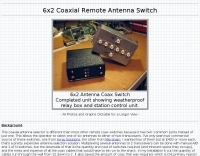 6x2 coaxial remote antenna switch, completed unit showing weatherproof relay box and station control unit.
 -
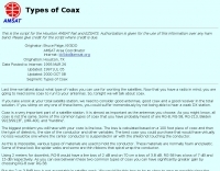 Coax is a very important part of a satellite station. It is almost as important as the antennas you choose. This article discusses choosing coaxial cables for satellite communication, emphasizing factors like line loss. It compares types such as RG-8, RG-58, Belden 9913/9913F, LMR-400, and hardline, highlighting their impact on signal preservation.
 -
 Over **10 million** antennas and flags have been sold worldwide by Firestik Antenna Company, a veteran-owned manufacturer specializing in both CB and amateur radio communication products. Their offerings include a range of antennas, mounting accessories, and coaxial cables, designed for various mobile and fixed applications. The company provides technical support and maintains a network of dealers for product availability. Firestik products are known for their fiberglass construction, which is evident in their _Firestik_ and _Firefly_ antenna lines. The company also produces unique items like the "342 mile per hour Firestik flag," highlighting their diverse manufacturing capabilities beyond just radio antennas. They emphasize their commitment to quality and customer service, including direct technical assistance. The company is located in Tempe, Arizona, and operates under the registered trademark of _Pal International Corporation_. They actively protect their brand, including variations like Firestick and Firestix, ensuring proper representation of their products in the market.
 -
 Operating a ZS6BKW antenna often involves understanding its lineage from the _G5RV_ design, with specific modifications by ZS6BKW to optimize performance on several bands. Through computational analysis and field measurements, the antenna's dimensions were refined to allow operation on 10, 12, 17, 20, and 40 meters without an antenna tuner. For 80, 30, and 15 meters, a tuner is necessary, though efficiency on 30 and 15 meters is noted as not particularly high. The physical configuration consists of two 13.755-meter radiating elements fed by a 12.20-meter section of 450-ohm ladder line. Tuning the antenna on the 20-meter band is critical, and any deviation in the ladder line's characteristic impedance necessitates recalculating the element lengths. The design is also referenced in the 12th edition of _Rothammel's Antennenbuch_, page 219. Proper common mode current suppression is crucial at the transition from ladder line to coaxial cable. This can be achieved with a common mode choke, such as several turns of coax wound into a coil or over a ferrite toroid like an Amidon T130. While a 1:1 balun is an option, it may introduce issues.
 -
 HD Communications Corp specializes in **RF and microwave amplifiers** engineered for demanding communication, defense, and industrial applications. Their product line includes precision-built, high-power solutions, along with RF connectors, filters, HF cables, and various accessories. The company also supplies tower hardware, valves, and tubes, catering to a broad spectrum of radio frequency infrastructure needs. Beyond amplifiers, HD Communications offers a range of **RF filters**, including low-pass filters, antenna filters, and solutions for RFI/TVI mitigation. Their inventory encompasses essential components like coaxial cable and various connector types, supporting both amateur radio and professional installations. The company operates as a manufacturer and vendor, providing direct sales of its specialized RF products.
 -
 A _Topfkreis_ antenna, also known as a "bicycle pump" antenna, is presented as a simple vertical design for the 70 cm band. This variant of the J-pole antenna is notable for not requiring a ground plane, simplifying deployment. The construction details specify using aluminum tubing for the radiating element, with precise measurements for the quarter-wavelength outer tube (32 mm diameter) and the three-quarter wavelength inner sliding tubes (10 mm and 8 mm). Feeding is via a 50-ohm coaxial cable connected 90 mm from the base of the central tube. This design can achieve a gain of **4 to 6 dB** when properly tuned using the adjustable radiating element. The article details the fabrication of a critical aluminum washer, suggesting a method using a hole saw and a drill press as a lathe for precise adjustment. The illustrated example is specifically for the 70-centimeter band, and the author, Pop, clarifies construction points in the comments, including material choices and assembly techniques, ensuring a robust build for VHF/UHF operation.
 -
 A 90-foot vertical antenna constructed from **aluminum irrigation tubing** is detailed, focusing on its innovative raising and lowering mechanism. The resource describes a **45-foot ginpole** system, allowing a single operator to erect or lower the antenna in minutes. It covers the mechanical design, including the pivot base, insulated joints for the tubing sections, and guy wire attachment points. The antenna consists of two 30-foot sections of 4-inch tubing and one 30-foot section of 2-inch tubing, stacked with the smaller diameter at the top. The electrical design incorporates PVC "condulet" boxes at the 30-foot and 60-foot points, housing relays to change the effective height for multi-band operation on 160, 80, 40, and 30 meters. Ferrite rod inductive chokes are used for DC control and to tune out gap capacitance. The antenna is fed with 1000 feet of open wire line, connected to a matching transformer comprising stacked toroids and a coaxial/toroidal balun. Grounding is achieved with a 3x3 foot grid of 16-gauge tinned copper wires with soldered crossovers.
 -
-
 BIRD RF power measuring, new and used, HENRY RF power amplifiers (used HF amps), TOHTSU coaxial relays, SAMLEX power supplies, RFI chokes reduce interference, Parts parts, tubes, Used amplifiers, radios, antennas and accessories, Los Angeles, CA.
 -
 The problem with making your own trapped HF antennas is usually getting the coaxial traps tuned to frequency.
 -
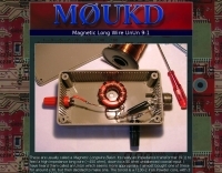 An impedance transformer (9:1) to feed a high impedance long wire (~450 ohm), down to a 50 ohm unbalanced coaxial input.
 -
 The Coaxman by Clear Signal Products, Inc. features a complete Wireman line of coaxial cable and antenna wire. Antenna wire, baluns, coax connectors, insulators, ladder line, magnet wire, rope.
 -
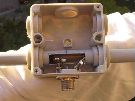
 Connecting centre fed antennas, dipoles, yagis, rhombics, loops to coaxial cable, unless care is taken, it is not difficult to end up with feeder radiation resulting in power loss and the radiation characteristics changes
 -
 Based on original G2BCX design this J-Pole antenna for the six meter band is made with a homemade ribbon cable. The antenna shown in this article includes a coaxial cable choke feed to remove RF currents from flowing on the outer of the cable.
 -
 A balun is a MUST for dipoles or similar antennas when they are feed with coaxial cables. Many hams connect the center conductor of the coaxial cable to one side of the dipole, and the shield to the other. Wrong!
 -
 Automatic band decoder, six way antenna relay, band reject coaxial stubs and more. Top Ten Devices is a two-man company formed in 1991 by N3RD and W2VJN.
 -
 The document provides a comprehensive overview of baluns, which are devices used to connect balanced loads, like dipole antennas, to unbalanced inputs, such as coaxial cables. It covers various types of baluns, including voltage and current baluns, and their design, construction, and testing. The text discusses the importance of baluns in preventing RF currents on coax shields and their applications in Ham radio setups. It also includes practical advice on selecting and using baluns based on antenna impedance and power ratings, along with detailed performance evaluations and construction tips for different balun configurations.
 -
 The Collins TRC-75 autotune linear amplifier, owned by JF2SVU, is presented with a focus on its internal modifications. This QRO amplifier utilizes three 4CX250 tubes in parallel for its final stage, delivering 1 KW output power. Notably, the amplifier achieves full power with only 100 mW of RF input, a characteristic often associated with Collins designs. The original 400 Hz power supply has been converted for easier shack integration, and the entire RF and power supply sections have been rehoused into a compact, clean enclosure. The control unit, positioned above the amplifier, features three meters for individual vacuum tube IP monitoring and a multi-meter on the right. A dedicated 7 MHz receiver, recently completed, is also part of this integrated system. The autotune functionality means the main amplifier unit only requires connections for power, control, and coaxial cables, simplifying its operation. Key components like the 4CX250 tubes and NF capacitors are visible, along with the gearing mechanism for the final tank circuit. A timer and relay system manages high-voltage delay and cooling fan off-delay, although the cooling fan's airflow is noted as somewhat insufficient. A central volume control, which experienced a contact issue, is also highlighted.
 -
 The G5RV multiband HF antenna, designed by Louis Varney (G5RV) in 1946, is a popular compromise antenna offering good overall performance on most HF bands when paired with an external antenna tuner. The basic full-size G5RV measures 102 feet across the top for 80 through 10 meter operation and is fed at the center via a 34-foot low-loss feed-stub. This interaction between the radiating section and the feed-stub facilitates matching across 80-10 meters with a standard tuner, often eliminating the need for ladder line directly to the shack. The antenna's design center frequency is 14.150 MHz, configured as a 3/2-wave dipole on 20 meters, with its 102-foot length derived from long-wire antenna formulas. Construction details emphasize the matching section, which can be open wire, ladder line (window-type), or TV twin lead. Each type has a specific velocity factor (VF) affecting its physical length for an electrical half-wave on 14 MHz; for instance, open wire requires 33.7 feet (VF 0.97), ladder line 31.3 feet (VF 0.90), and TV twin lead 28.5 feet (VF 0.82). The article provides formulas for calculating these lengths and discusses the antenna's behavior on individual bands, from 3.5 MHz where it acts as a shortened dipole, to 28 MHz where it functions as two three-half-wave long-wire antennas fed in-phase. Practical construction notes include recommendations for vertical descent of the matching section, sealing the coax junction, providing strain relief, and winding a coaxial choke coil to mitigate common mode current. The resource also presents dimensions for double-size (204 ft) and half-size (51 ft) G5RV versions, along with their corresponding matching section lengths for various line types, making it a versatile reference for hams considering this classic wire antenna.
 -
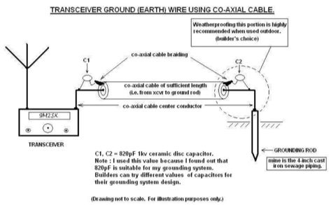 Improper grounding or earthing system can cause several unwanted RF interferences (RFI) to television sets, broadcast receivers, hi-fi sets and telephone sets. In this Article the author explain how to setup a proper radio shack grounding using coaxial cable and ceramic disc capacitor
 -
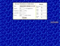 Calculate power loss depending on coax cable you use
 -
 The Resonant Feedline Dipole (RFD) HF antenna design utilizes a single piece of coaxial cable and a stranded wire section, forming a 1/4-wavelength radiator. This configuration, based on a 1997 ARRL Handbook design (page 20.17), functions by RF traveling on the inside of the coax shield and returning on the outside, creating the second half of the dipole. A choke wound into the feedline prevents RF current from flowing back down the feedline. Construction details include using RG-58a/u coax for a 75m version, with a 1/4-wavelength section of stranded wire soldered to the center conductor. The document provides choke dimensions for RG-213, RG-8, and RG-58 coax across 3.5 MHz to 28 MHz, specifying cable length and number of turns. Dipole dimensions are also tabulated for frequencies from 3.6 MHz to 28.4 MHz, listing overall length and individual leg lengths. Field tests included deployment near Bryson City at 5 feet off the ground and as a sloper during WCARS Field Day in Asheville, yielding successful local and regional contacts.
 -
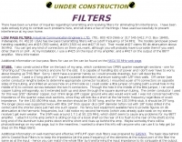
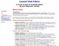 A range of easy-to-build RFI filters by John Regnault, G4SWX
 -
 Radio frequency systems require robust protection against transient voltage events, which can severely damage sensitive equipment. This resource details a range of **RF surge protection** devices, including models with DC Pass, DC Block, Bias T, and Ultra Low PIM characteristics, designed to safeguard critical infrastructure. It also presents various RF filtering solutions and interconnect components, emphasizing their role in maintaining signal integrity and operational continuity across diverse applications. The site provides information on products engineered for both RF and data line protection, highlighting their utility in preventing downtime and equipment loss. Specific product categories encompass coaxial protectors, grounding items, and fiber optic solutions, indicating a broad scope of application from amateur radio installations to industrial and telecommunications networks. Furthermore, the resource mentions the availability of NOM-certified products and offers same-day shipping for many items, underscoring a commitment to rapid deployment and compliance with industry standards.
 -
 Details Allied Wire and Cable's extensive product catalog, focusing on its role as both a distributor and manufacturer of specialized wiring solutions. The resource highlights the availability of electronic and electrical wire, various cable types, tubing, and pre-assembled cable solutions. It also specifies their capability in **custom cable design**, addressing unique requirements for specific applications. The site presents information on flexible cable options and a broad spectrum of wire and cable specifications, catering to diverse industrial and technical needs. It outlines the company's capacity to provide tailored solutions beyond standard off-the-shelf products, emphasizing their engineering and manufacturing expertise. Key offerings include **coaxial cable**, connectors, and general wiring components, positioning the company as a comprehensive source for connectivity infrastructure. The content implicitly supports applications ranging from industrial automation to specialized radio frequency installations.
 -
 Demonstrates the construction of a 144 MHz turnstile antenna, detailing its design for omnidirectional, horizontally polarized VHF operation. The resource outlines the physical dimensions and materials required, including specific lengths for the radiating elements and the use of _RG-58_ coaxial cable for phasing. It covers the assembly process, emphasizing the critical spacing and connection points to achieve the desired radiation pattern and impedance matching for the _2-meter band_. The article presents measured _SWR_ performance across the 144-146 MHz segment, showing a low SWR of 1.2:1 at 144.5 MHz, which is suitable for general VHF use. It compares the turnstile's performance to a 9-element Yagi, noting the turnstile's advantage in providing consistent signal strength from all directions without requiring a rotator. Practical application for local FM simplex and repeater operations is implied, offering a simple yet effective antenna solution for fixed or portable stations.
 -
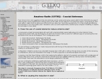 G3TXQ study on coaxial cable demonstrate that it can reduce an element's length by something approaching the Velocity Factor of the cable
 -
-
 The resource presents a detailed schematic for constructing a dual-band vertical antenna, specifically designed for operation on the 2-meter and 70-centimeter amateur radio bands. It illustrates the physical layout, critical dimensions, and component placement necessary for successful replication. Key elements such as the radiating elements, phasing sections, and feed point are clearly depicted, providing a visual guide for radio amateurs undertaking a homebrew antenna project. The diagram specifies the lengths for the VHF and UHF sections, indicating how these elements are integrated to achieve dual-band functionality from a single coaxial feedline. It also implies the use of common materials readily available to most experimenters, focusing on simplicity and effectiveness in its design. The visual format of a GIF image ensures direct access to the construction details without requiring extensive textual interpretation. This schematic serves as a practical reference for hams interested in building a compact, efficient vertical antenna for local and regional FM communications, offering a proven design for immediate implementation.
 -
 Manufactures and sells coaxial connectors, coaxial adapters, coaxial cables, attenuators, directional couplers, fiber optic connectors, fiber optic adapters, fiber optic cables, coaxial switches, terminators, twinax connectors and cables and tools.
 -
 Svetlana tubes also Russian capacitors,vacuum and coaxial relay, for RF Power Linear Amplifier builders. Amateur-Radio, Broadcast. Full Online Catalog.
 -
 Showcasing a specialized product line, Advanced Receiver Research presents a comprehensive catalog of **low noise preamplifiers** and microwave **Gunnplexers**. The offerings span a broad spectrum of radio frequencies, from VLF, LF, MF, and HF bands up through VHF, UHF, and microwave, catering to diverse applications including amateur radio, commercial installations, and military systems. Their product range includes mast-mount preamplifiers, inline attenuators, power dividers, and various coaxial components. My own experience with similar low-noise front ends for weak-signal work on 2 meters and 70 centimeters underscores the critical role such components play in maximizing receiver sensitivity, especially when chasing distant DX or engaging in EME. The detailed product descriptions and technical specifications provided on the site allow operators to select the optimal preamplifier for their specific band and noise figure requirements, essential for improving signal-to-noise ratio. The site also lists specialized products for unique applications like Nuclear Magnetic Resonance (NMR) and Studio Transmitter Links (STL), demonstrating a depth of engineering capability beyond typical amateur radio fare. This breadth of offerings, coupled with clear ordering and warranty information, positions Advanced Receiver Research as a key supplier for high-performance RF components.
 -
-
 This resource details the four primary functions of a ground system: lightning energy dispersion, equipment safety, RF return path provision for end-fed antennas, and management of induced RF currents. It clarifies that a ground system's effectiveness varies depending on its specific function, noting that a good lightning ground might not be an effective RF ground. The content emphasizes that proper antenna system design, including baluns and appropriate feedline lengths, often negates the need for an RF station ground to mitigate common mode currents or RFI in the shack. The article quantifies lightning energy, stating its peak is in the dozens or hundreds of kilohertz, with damaging energy extending to hundreds of megahertz, and currents reaching thousands of amperes. It recommends solid, wide, smooth copper surfaces for ground leads to achieve low impedance across a wide frequency range. The author, W8JI, shares practical insights from his station, which includes two 300-ft towers and four 130-ft wire verticals, detailing his use of common point grounds and _DX Engineering RR-8 HD_ antenna switches for lightning protection without coaxial surge protectors. Specific examples of antenna systems prone to common mode current problems are listed, such as random wire antennas without proper feedline lengths and off-center fed dipoles. The text also explains how a ground screen or radial system can reduce local noise sensitivity for vertically polarized antennas by covering the lossy earth.
 -
 Understanding Common Mode and Differential Mode Currents on Transmission Lines by K9YC
 -
 Demonstrates the adaptation and construction of a 7-element DK7ZB Yagi antenna for the 4-meter band (70 MHz), utilizing components from a defunct 2-meter CUE DEE Yagi. The resource details the modifications made to the original DK7ZB design to fit the shorter CUE DEE boom length, specifically adjusting element lengths for 6mm rod elements while reusing existing mounting holes for the reflector and last director. It provides precise element lengths for the reflector, dipole (12mm aluminum tube), and five directors, along with a note on cutting elements for transport. The article includes a 4NEC2 simulation file for performance analysis and an SWR plot, confirming the antenna's electrical characteristics. It also specifies the calculation for the quarter-wavelength matching cable using SAT752F coaxial cable, resulting in a 909mm length. Practical application is shown with the finished antenna in operation at JO20XC, listing several activated Maidenhead squares such as JO56PA and JP40KS, validating its effectiveness for portable 70 MHz operations.
 -
-
 Dodgy plans to make Archimedean spiral antenna for RTLSDR software defined radio receiver. Made of two equal lengths of coaxial cable seems to be the easiest circularly polarized antenna to make that will cover a broad range of the rtlsdr dongles E4000 tuners
 -
 The X80 multi-band HF vertical antenna, a commercial iteration of the Rybakov design, exhibits a physical length of 5.5 meters, or approximately 18 feet, and is constructed from aluminum tubing. It operates as a non-resonant vertical, requiring an external antenna tuner for impedance matching across its intended operating frequencies. The antenna's design incorporates a 1:4 UNUN at its base, facilitating a nominal 50-ohm feed point impedance for the coaxial cable. Performance observations indicate effective operation on 40 meters, 20 meters, 15 meters, and 10 meters, with reduced efficiency on 80 meters and 160 meters due to its relatively short electrical length for these lower bands. Comparative analysis with a G5RV dipole and a half-wave end-fed antenna reveals the X80 offers a lower take-off angle, beneficial for DX contacts, particularly on the higher HF bands. Field tests conducted with an Icom IC-706MKIIG transceiver and an LDG AT-100ProII autotuner demonstrate the X80's ability to achieve acceptable SWR across 80m through 10m. The antenna's compact footprint and ease of deployment make it suitable for restricted spaces or portable operations, though its performance on 80 meters is noted as a compromise compared to full-size resonant antennas.