Search results
Query: common mode
Links: 155 | Categories: 1
Categories
-
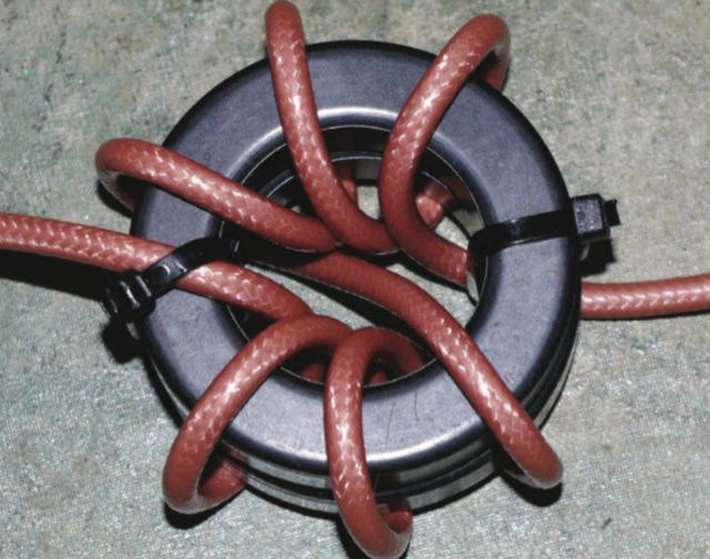 May 2015 Radcom Article on common-mode chokes that can be used for control cables, phone lines, but mostly on typical HF antenna systems. This article explain what common mode chokes does, why you meay need one, properties common mode chokes should have, how to build and measure performances.
 -
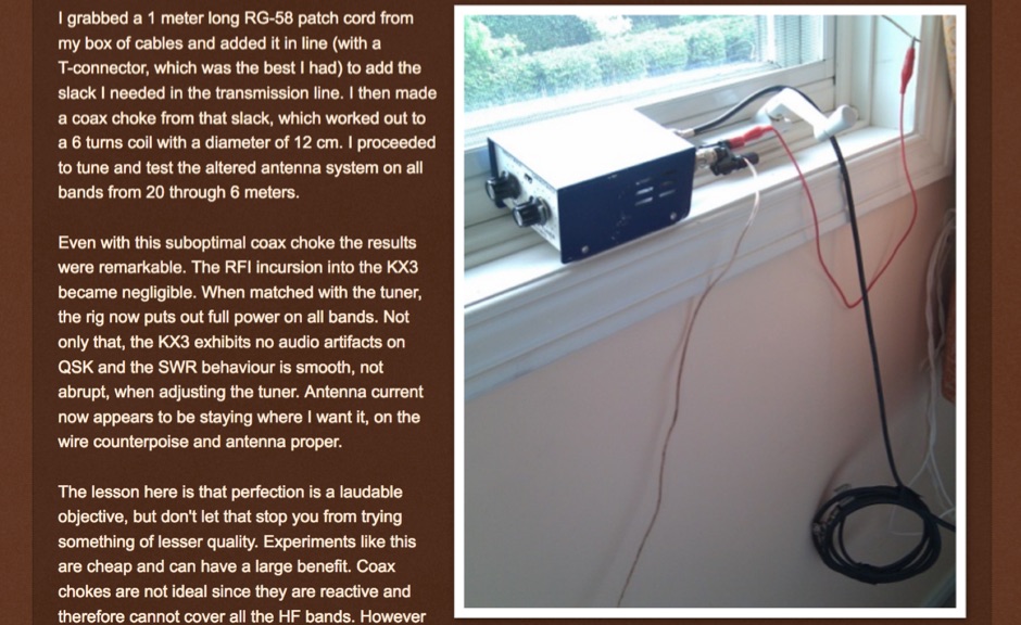 Stop common-mode current when transmitting with an end-fed antenna. Unbalanced antennas are very prone to currents on the outside of the coax.
 -
 **LDG Z100** automatic tuner repair focuses on toroid replacement and troubleshooting. The guide provides detailed steps for diagnosing and fixing common issues with the toroid, which is crucial for the tuner's performance. It includes specific instructions on disassembling the unit, identifying faulty components, and sourcing replacements. The document is technical, requiring familiarity with electronic components and soldering techniques. It emphasizes the importance of using the correct toroid specifications to ensure optimal functionality. Successful repair of the **LDG Z100** ATU restores its ability to match a wide range of antennas, enhancing transmission efficiency. The guide compares the performance before and after the repair, highlighting improvements in SWR readings and overall reliability. Practical application of this repair extends the life of the tuner, making it a cost-effective solution for amateur radio operators. The document serves as a reference for similar repairs on other models, providing insights into common issues and solutions. It is a valuable resource for those looking to maintain their equipment without resorting to professional services.
 -
 MyAntennas.com offers standard and custom made multiband antennas, Baluns, Common Mode chokes and accessories. All products are designed and made by Danny Horvat, E73M an antenna design engineer formerly employed by Cushcraft Corporation.
 -
 The 60-page PDF document, "Antenna Systems and Theory For The Non-Technical Ham" by Jim Abercrombie, N4JA, provides a foundational understanding of antenna systems. It explains basic antenna theory, including how antennas work, electromagnetic wave polarization, and the role of frequency. The resource details various antenna types such as flat top dipoles, inverted-V dipoles, shortened loaded dipoles, G5RV dipoles, Carolina Windoms, and end-fed configurations. Vertical antennas, including ground-mounted trapped verticals and inverted-L verticals, are also covered. Directional beam antennas like monoband Yagis, cubical quads, and log-periodic arrays are discussed. Propagation modes, including ground-wave, direct wave, and skywave propagation, are explained in detail, with specific attention to the D, E, and F layers of the ionosphere and their effects on HF communication. Technical concepts such as standing wave ratio, decibels, resistance, and reactance are defined, along with calculations for half-wave resonant dipole lengths. The document addresses feed-line radiation, balun applications, and critical antenna and tower safety considerations. It aims to dispel common antenna myths and educate hams on making informed antenna choices.
 -
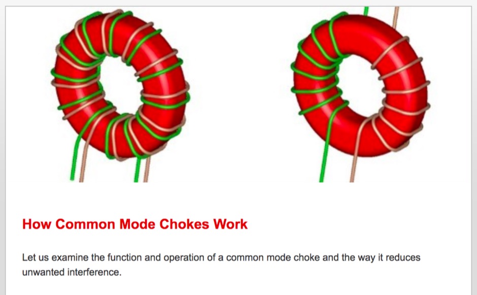 Examine the function and operation of a common mode choke and the way it reduces unwanted interference. Common Mode Choke vs. Single Choke
 -
 This resource provides fundamental guidelines for optimizing mobile amateur radio antenna installations. It addresses critical factors such as achieving an adequate ground plane, minimizing common mode current, and reducing ignition noise. Specific recommendations include mounting antennas on the vehicle's roof for superior radiation patterns and utilizing proper feedline routing to mitigate RF interference within the vehicle's electrical system. The content details the impact of antenna placement on Standing Wave Ratio (SWR) and overall radiated power, emphasizing the importance of a solid electrical connection to the vehicle chassis. It also discusses strategies for noise suppression, such as bonding body panels and employing ferrite chokes on power leads. The information presented is practical for hams seeking to improve their mobile station's efficiency and reduce RF-related operational issues.
 -
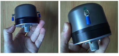 Presents a construction project for a 1:1 current balun, specifically detailing the _Sorbie Balun and Bottle Choke_ design. The resource outlines the winding technique, employing 4+4 turns of mini coaxial cable on a large ferrite core, and provides insights into the physical assembly. It includes specific material recommendations, such as the type of ferrite and coaxial cable, crucial for achieving the desired impedance transformation and common-mode current suppression. The content covers the practical steps involved in building the balun, from preparing the coaxial cable to securing the windings on the ferrite toroid. It also discusses the integration of the balun into an antenna system, emphasizing its role in maintaining pattern integrity and reducing RF interference in the shack. The resource offers a clear, step-by-step approach, making the project accessible for homebrewers. Illustrations and photographs accompany the text, visually guiding the builder through each stage of construction. The article concludes with performance expectations and considerations for deployment, ensuring the constructed balun functions effectively across the intended frequency range.
 -
 Operating the _Icom IC-746_ HF/VHF transceiver often presents specific technical questions, and this resource compiles a comprehensive Frequently Asked Questions (FAQ) document in an ASCII text format. It details common inquiries and solutions related to the rig's functionality, accessories, and potential modifications. The content is structured into distinct sections addressing general information, power supplies, antennas, microphones, keyers, amplifiers, TNC integration, and optional IF filters. The FAQ provides practical guidance on topics such as configuring the internal automatic antenna tuning unit (ATU), selecting appropriate power supplies, and understanding microphone pin-outs. It also delves into advanced subjects like computer control via CI-V, wiring for PSK31 operation, and troubleshooting common issues like low S-meter readings on 2m FM or loose tuning shafts. Specific questions cover the installation of optional IF filters, comparing Inrad versus Icom filters, and optimizing filter combinations for various modes. Furthermore, the document outlines various hardware and firmware modifications, including those for increasing monitor volume, replacing LCD driver transistors, and implementing a "poor man's TCXO." It even touches upon untested modifications, such as replacing PIN diodes in the demodulator. The FAQ also lists manual errata and discrepancies, offering a robust knowledge base for IC-746 owners seeking to optimize their station or resolve operational challenges.
 -
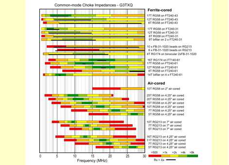 Chart that present results of impedance measurements made on a variety of common-mode choke implementations across the frequency range 1MHz to 30MHz by G3TXQ
 -
 About windom antennas and OCF dipoles, tricks on covering more bands moving feed-points and potential problems. Problems caused by common mode currents in OCF dipoles
 -
 Marshall G. Emm, N1FN, meticulously examines iambic keying, dissecting its historical introduction in the late 1950s with transistorized electronic keyers and its purported advantages. The resource defines keying systems, electronic keyers, and various paddle types, including single-lever and dual-lever paddles, clarifying the distinction between iambic keyers and the iambic sending technique itself. It details the two main types of squeeze keying: true squeeze for alternating dot-dash strings and character insertion for specific elements within a character. N1FN critically evaluates the actual efficiency gains of iambic keying, referencing Chuck Adams, K7QO's, keystroke analysis. While a straight key to bug transition yields a 34.1% reduction and a bug to non-iambic keyer offers 16.1%, iambic keying provides only an 11% theoretical improvement. However, considering typical QSO text and Morse code's inherent optimization for common letters, the practical efficiency gain is estimated at a modest 4-6%. The article also highlights how iambic keying's reliance on precise timing gates can impose a speed limit, making it less effective above 40 WPM, where many operators revert to non-iambic methods or single-lever paddles.
 -
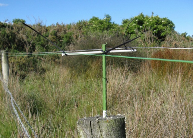 How do two-wire reversible direction Beverages work, an excellent document that explains fundamentals of beverage antennas. This article details the design and performance of a reversible beverage antenna. Leveraging orthogonality between common mode and differential mode currents on a 2-wire line, this antenna facilitates independent reception from both ends. While common mode signals arrive and are summed on a transformer's secondary for common mode reception, differential mode signals induce anti-phase currents, providing individual reception. Various measurements explore impedance, transmission loss, and F/B ratio, highlighting the antenna's effectiveness and areas for improvement. Notably, increasing the antenna's height significantly improved performance.
 -
 Operating a ham station often involves encountering radio frequency interference (RFI), RF feedback, or RF burns, which are frequently misattributed to poor equipment grounding. This resource meticulously dissects these assumptions, asserting that RF grounds on the operating desk often merely mask more significant system flaws. It identifies five primary causes for RF problems, including antenna system design flaws, proximity of the antenna to the operating position, DC power supply ground loops, equipment design defects, and poorly installed connectors or defective cables. The content emphasizes that issues like "hot cabinets" or changes in SWR when connecting a ground indicate substantial RF flowing over wiring or cabinets, a phenomenon known as common-mode current. The article provides detailed explanations of common-mode current generation, particularly from single-wire fed antennas like longwires, random wires, and OCF dipoles, which inherently present high levels of RF in the shack. It also illustrates how vertical antennas, lacking a perfect ground system, can excite feed lines with significant common-mode current. Through simulations, the author demonstrates how a dipole without a proper _balun_ can cause RF problems at the operating desk, showing current patterns and voltage distributions on feed line shields. The discussion extends to the proper application of _RF isolators_ and _ferrite beads_, clarifying their role in modifying common-mode impedance on cable shields and cautioning against their use as a band-aid for fundamental system defects. The resource advocates for correcting the actual source of RF problems, such as antenna system issues or poor connector mounting, rather than relying on internal shack grounding or isolators. It highlights that properly functioning two-conductor feed lines, like coaxial or open-wire lines, should result in minimal RF levels at the operating position, even without a desk RF ground. The author shares personal experience, noting that his stations since the late 1970s have operated without RF grounds at the desks, relying instead on proper antenna system design and feed line integrity.
 -
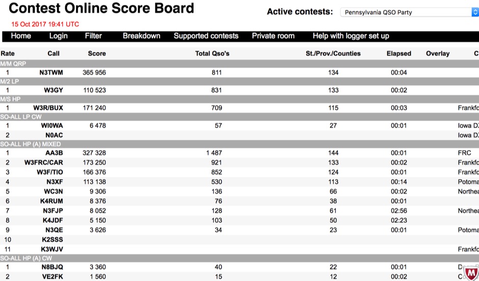 Aggregating real-time contest scores, this online scoreboard serves as a central hub for participants and spectators to monitor live progress during amateur radio competitions. It directly interfaces with widely used contest logging programs, collecting score data as operators make contacts. The platform then processes and displays these scores on dedicated contest pages, offering an immediate overview of standings. Supporting a diverse range of **DX contests**, the system accommodates various operating modes and rulesets. It facilitates score tracking for events like the YB DX RTTY, RSGB Commonwealth (BERU), EA PSK63, and the South America 10 Meter contest, among others. This functionality allows contesters to gauge their performance against competitors instantaneously, fostering dynamic participation. The scoreboard's integration with multiple contest log software applications ensures broad compatibility, making it accessible to a significant portion of the contesting community. It provides a crucial service by centralizing score visibility, enhancing the competitive experience for **amateur radio operators** worldwide.
 -
 The CAT and audio interface version 3 project by PA5CA presents a comprehensive solution for integrating amateur radio transceivers with computer sound cards, facilitating digital mode operation and CAT control. It includes detailed schematics for the interface circuitry, illustrating the isolation transformers for audio paths and optocouplers for CAT data lines, ensuring robust electrical separation between radio and PC. The resource also provides PCB layouts, enabling constructors to fabricate their own boards for this specific design. The project outlines the component selection and assembly process, emphasizing the use of readily available parts to build a reliable interface. It addresses common challenges in sound card interfacing, such as ground loops and RF interference, through its isolated design. This construction guide offers practical insights into building a functional interface, making it suitable for hams interested in DIY radio accessories for digital modes like FT8, RTTY, and PSK31.
 -
 1.5 dB of matched line loss can be calculated for a given transmission line using this online tool, which employs a model calibrated from empirical data. The calculator allows radio amateurs to input specific transmission line types, such as _RG-8_ or _RG-58_, and then determine the expected signal attenuation. This is crucial for optimizing antenna system efficiency and understanding power delivery to the radiating element, especially for HF and VHF operations where feedline losses can significantly impact performance. Beyond matched loss, the calculator also provides an estimate for mismatched loss if the Standing Wave Ratio (SWR) is specified. This feature helps operators quantify the additional power loss due to impedance discontinuities between the transceiver, feedline, and antenna, which is a common concern in amateur radio installations. Accurate loss calculations are vital for effective station design and for predicting actual radiated power. The tool's utility extends to various operating scenarios, from fixed station setups to portable deployments, aiding in the selection of appropriate feedline lengths and types to minimize signal degradation. Understanding these losses is a fundamental aspect of maximizing the effectiveness of any amateur radio antenna system.
 -
 A 50.200 MHz Moxon antenna for the 6-meter band is detailed, providing practical construction guidance for amateur radio operators. The design utilizes 3/4" aluminum angle stock for the elements, joined with wood molding and 1/4 x 20 hardware. Key components include an SO-239 connector for the feedpoint and a **choke balun** made from coiled RG-58 coax, ensuring proper impedance matching and minimizing common mode current. The antenna measures approximately 29 inches deep by just under 7 feet long, making it suitable for portable operations. Specific dimensions, based on **Cebik's nomenclature**, are provided for the driven element and reflector. The resource also offers modeling hints, suggesting an effective element diameter of 1 inch for software simulations and emphasizing element sizing based on corner screws rather than end-to-end measurements.
 -
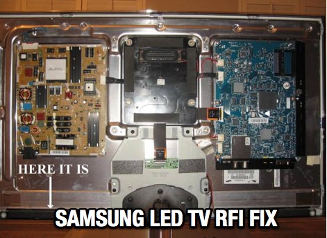 A workaround to common RF interference on Samsung TV LED causing several issues like changing channel, swithcing to demo mode, or changing volume.
 -
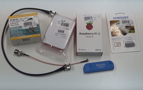 How to receive automatically NOAA wather satellite images with a Raspberry Pi and a RTL SDR. This project requires a Raspberry Pi 3 Model B a common NooElec SDR Dongle and a QFH Antenna in the attic. Article explains how to setup and configure software but no instructions on antenna.
 -
 Demonstrates the fundamental principles for connecting a personal computer to a ham radio transceiver, specifically for utilizing sound card-based digital mode software like those in the MM Hamsoft suite. It details the basic hardware setup, emphasizing the use of shielded leads and proper audio routing from the radio's output to the sound card's input, and from the sound card's output to the radio's microphone or data input. The resource highlights the critical need for transmit attenuation, suggesting a 100:1 voltage divider to prevent overdriving the transmitter's audio stage, and mentions the optional addition of ferrite beads and decoupling capacitors for RFI mitigation. The guide also points to external resources for more detailed pin-outs and interface schematics, such as a specific QSL.net page, and recommends consulting the help files within MM Hamsoft programs for interfacing specifics. It underscores that while the process is straightforward, understanding the audio level management and proper cabling is key to successful operation. The author, VE5KC, provides practical advice drawn from common issues encountered by operators setting up digital mode stations.
 -
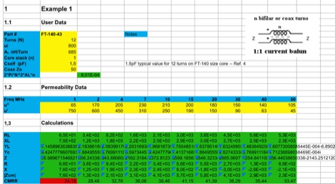 This EXCEL Program Worksheet calculates the common-mode impedance of a 1:1 Guanella (current) balun which is placed at the feed point of a balanced antenna system fed via coax.
 -
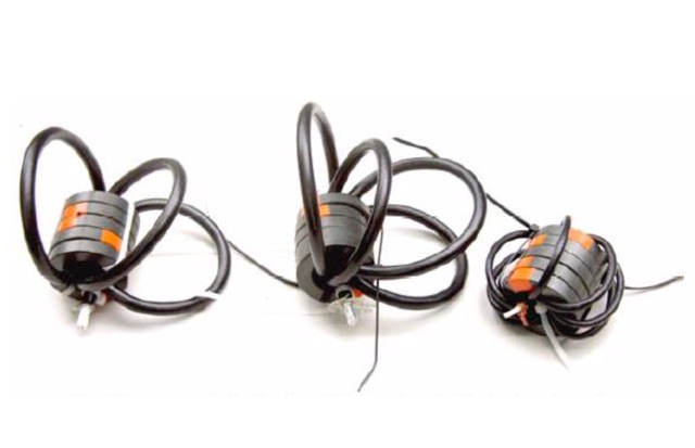 In this article, author examine stresses placed on common-mode chokes (aka baluns) as hams use/abuse them, examine the efficiency of simple dipole multi- band antennas and their feed systems. Stressing a Balun.
 -
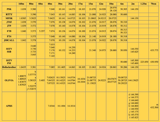 A summary of common calling frequency for each digital mode on that band.
 -
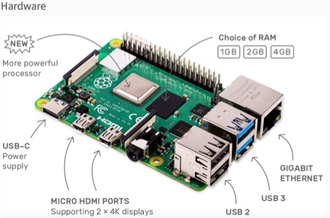 This resource is an online tutorial focused on setting up the Raspberry Pi for amateur radio applications. It covers the installation and configuration of various software packages tailored for digital communications and protocols, including _Packet Radio_ with Hamlib and Direwolf, as well as data modes like FLDigi and WSJT-X. The guide also details the integration of hardware components such as GPS clocks for time synchronization and real-time clocks for enhanced functionality. Users will find instructions for installing software like GPredict for satellite tracking and GQRX for software-defined radio (SDR) applications. The tutorial emphasizes practical steps, including the use of command-line inputs in the Raspberry Pi OS terminal, and provides troubleshooting tips for common issues such as faulty SD cards or insufficient power supplies. Operators are encouraged to explore various applications, including APRS iGates and WSPR beacons, to enhance their ham radio experience. The material is designed for licensed amateur radio operators with basic knowledge of electronics and computing.
 -
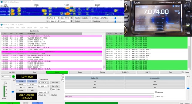 The _Icom IC-7300_ transceiver, a popular SDR rig, can be readily configured for digital modes like FT8 using _WSJT-X_ software. This guide details the necessary steps, from downloading the correct version of WSJT-X to configuring the radio's USB audio and CAT control settings. It emphasizes a straightforward approach, aiming to simplify the often complex initial setup for new digital mode operators. K0PIR shares his practical experience, outlining the specific menu settings on the IC-7300, such as USB SEND/DPT and USB MOD LEVEL, which are crucial for proper signal modulation and transmission. The resource also covers the integration of WSJT-X's built-in logging capabilities, streamlining the process of recording digital contacts without needing external logging software immediately. This setup allows for efficient operation on various HF bands. Two embedded videos further illustrate the configuration process, providing visual aids for each step, from initial software installation to making the first FT8 contact. The author's method focuses on minimizing common setup hurdles.
 -
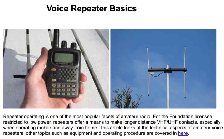 Sixty-meter repeaters typically use a 1 MHz frequency separation between input and output, while 2-meter repeaters commonly employ a **600 kHz** split and 70-centimeter repeaters use a **5 MHz** offset. This article details the fundamental technical principles of amateur voice repeaters, explaining how they extend VHF/UHF communication range by receiving on one frequency and simultaneously retransmitting on another. It covers essential components such as receivers, transmitters, filters, and antennas, often situated on elevated locations for optimal coverage. The resource delves into the critical challenge of _desensing_—where the repeater's strong transmit signal overpowers its own receiver—and the engineering solutions employed, including antenna separation and the use of high-Q cavity filters. It also explores various control and timing systems, from basic squelch activation to more sophisticated microcontroller-based boards that manage functions like voice identification, time-out timers, and fault protection. Different access methods are discussed, including open access, toneburst, CTCSS subtone, and DTMF, each offering distinct advantages for managing repeater usage and mitigating interference. Furthermore, the article examines repeater linking, both conventional RF methods and modern internet-based solutions, highlighting how linking expands coverage and promotes activity across multiple repeaters or bands. It introduces less common repeater types such as 'parrot' repeaters, which use a single frequency and digital voice recording, and linear translators, capable of relaying multiple signals and modes simultaneously across different bands, often found in amateur satellites.
 -
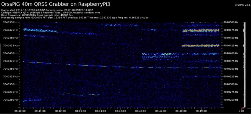 Monitoring extremely weak signals in the QRSS (Very Slow Morse) mode requires specialized receiving and processing capabilities to extract information below the typical noise floor. This project provides a software solution, _QrssPiG_, designed to run on a Raspberry Pi, enabling it to function as a dedicated QRSS grabber. It interfaces with various Software Defined Radio (SDR) devices, including the popular _rtl-sdr_ dongles and _HackRF_ units, to acquire raw I/Q data streams. The software then performs the necessary signal processing to visualize and decode these faint, long-duration CW transmissions, often operating with milliwatts of power. The system leverages the computational power of the Raspberry Pi for real-time signal analysis, allowing hams to participate in QRSS experiments and monitor distant beacons. It supports different SDR hardware, offering flexibility in setup and deployment for home stations or remote monitoring sites. The project includes detailed instructions for installation and configuration, making it accessible for those familiar with Linux environments. This grabber is particularly useful for tracking propagation on the LF and HF bands where QRSS activity is common, providing a visual representation of signal presence over extended periods.
 -
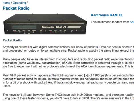 Introduction to packet radio and answers to common questions about this digital mode and about services you can use by VKFAQ
 -
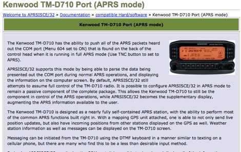 The Kenwood TM-D710 is designed as a nearly fully self-contained APRS station, with the ability to perform most of the common APRS functions built right in.
 -
 The High Point Amateur Radio Club (HPARC), operating under the callsign W4UA, provides a central hub for amateur radio enthusiasts in High Point, North Carolina, and surrounding communities. The club's website outlines its long-standing traditions and civic service, which date back to the 1930s, highlighting its sustained leadership and strong membership support over decades. It serves as a resource for individuals interested in obtaining or upgrading an FCC amateur radio license, offering assistance through direct contact with club officers. The site also features a newsletter archive for meeting notices and information on club activities, including Field Day. HPARC's diverse membership shares a common interest in the amateur radio hobby, encompassing various aspects such as VHF, UHF, HF, and digital modes like D-STAR. The club's commitment to public service is evident through its involvement in ARES and Skywarn, alongside educational initiatives for new hams and those pursuing license upgrades. The site also lists repeaters and provides information on emergency communications, technical projects, and participation in events like DXCC and contests, reflecting the broad interests of its members.
 -
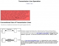 The resource, "Conventional Use of Transmission Line," meticulously details the operational principles of transmission lines, emphasizing the Transverse Electromagnetic (TEM) mode of energy transfer. It clarifies that for a line to function purely as a transmission line, all currents must be confined internally, with external fields ideally zero. The discussion differentiates between balanced and unbalanced lines, asserting that while both require equal and opposite currents within the conductors, the key distinction lies in the voltage relationship of each conductor to the surrounding environment. It highlights that a good antenna pattern does not inherently confirm proper feeder balance, and that common-mode currents can lead to RF in the shack and increased noise levels, even without pattern distortion. The article further explains that a transmission line can become a radiating conductor if energy is applied in a non-TEM mode, leading to common-mode issues. It cites classic texts like Jordan and Balmain's "_Electromagnetic Waves and Radiating Systems_" and Kraus's "_Antennas_" to support its definitions of TEM mode operation. The content also explores non-transmission line applications of parallel or concentric conductors, such as _coaxial dipoles_ and _folded dipoles_, which intentionally operate in non-TEM modes for antenna functionality. The author, _W8JI_, stresses that simply measuring equal currents is insufficient to confirm a balanced feeder; phase and voltage balance to ground are equally critical.
 -
 The Tri-pole antenna, a clever modification of a standard dipole, allows for dual-band operation by integrating a third element. This design effectively shortens the overall dipole length by 10 to 20 percent, simplifying antenna rotation and offering a compact footprint. KK4OBI's article delves into the operational principles, using a 6 and 10-meter Tri-pole as a primary example, and provides comprehensive instructions for constructing any Tri-pole antenna within the 6 to 15-meter range. Key to the Tri-pole's performance is its off-center feed, necessitating a common mode choke at the feed point for optimal tuning and reduced noise. The author outlines a methodical approach to determining element dimensions, starting with a vertical element frequency calculated as 0.47 times the sum of the desired upper and lower band frequencies. This calculation, along with K-values derived from trend lines, guides the initial lengths for the horizontal arms, demonstrating how a 10m-6m Tri-pole can achieve a total horizontal length 78% shorter than a conventional 10-meter dipole. Tuning and balancing are critical, with the article detailing adjustments to arm lengths and the vertical element to achieve balanced SWR values, as validated through 4NEC2 simulations. Radiation patterns are analyzed at various elevations, showing gains around 5.7 dBi and favorable take-off angles for DX contacts. Construction details specify aluminum tubing dimensions, U-bolts, and an SO-239 connector, emphasizing the importance of a ferrite-based choke for wideband operation.
 -
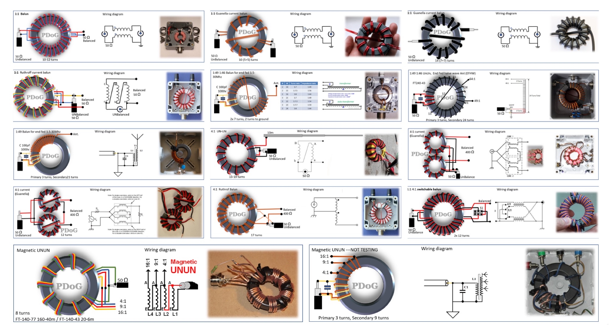 This page provides a detailed guide on the Guanella Current Balun for ham radio operators. The author shares very nice schematics, photos, and explanations on the construction and use of this type of balun. The content explains when a balun is needed and how it can help with common-mode currents in antenna systems. It also discusses the construction process, including winding the balun around a ferrite core. This resource is useful for hams looking to improve their antenna systems and reduce common-mode currents for better performance. This article is in Dutch.
 -
 Extended Single SideBand is any SSB transmission that exceeds the audio bandwidth of common 2.9kHz SSB J3E modes by essb.us
 -
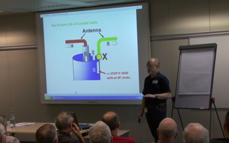 Our ideas about HF baluns have changed dramatically in recent years. The focus today is very much on suppressing unwanted common-mode RF currents, to reduce both the received noise levels and the risks of causing interference on transmit.
 -
 The Linked Dipole is a multiband antenna designed for 80/60/40/30/20m bands, optimized for the (tr)uSDX low bands configuration. It incorporates a 1:1 Balun to prevent common mode currents, ensuring balanced operation with coaxial cable. The Balun, wound on an FT140-43 core, achieves 37-40dB attenuation. The design includes a 3D-printable housing for compactness and waterproofing, with labeled link insulators for ease of use. Wire lengths were meticulously adjusted for optimal performance with a 7m pole and 3m rope extension, ensuring the antenna's ends are off the ground for improved behavior. The project includes downloadable printables for DIY construction.
 -
-
 Constructing a dual-band antenna for 40 and 20 meters often involves compromises in size or complexity. This resource presents a compact _open sleeve dipole_ design that addresses these challenges by using 450-ohm ladder line and folded elements to achieve a total length of approximately **17.17 meters**, significantly shorter than a full-size 40-meter dipole. The design leverages electromagnetic coupling, where a primary radiator handles the 40-meter band, and a second conductor resonates on 20 meters without direct electrical connection. This configuration eliminates the need for traditional traps, loading coils, or switching components, simplifying construction and reducing potential loss points. The antenna is fed with RG-58C/U coaxial cable, and a common-mode choke is recommended at the feed point to suppress sheath currents, ensuring a cleaner radiation pattern and minimizing RF in the shack. The design is well-suited for portable operations, field deployments, temporary installations, and restricted urban environments where space is a premium, offering solid performance on both HF bands.
 -
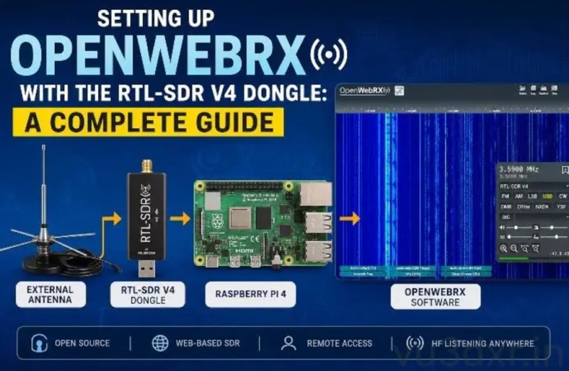 The _RTL-SDR V4_ dongle offers a tuning range from approximately 500 kHz to 1.7 GHz, encompassing HF, VHF, UHF, and microwave amateur allocations, with direct sampling improvements for HF reception. This guide outlines two primary installation methods for _OpenWebRX_ on a Raspberry Pi: utilizing an official Raspberry Pi image or employing a Docker installation. It also provides specific recommendations for Raspberry Pi models such as the 3/3B+, 4, and Zero 2 W, alongside practical advice for antenna selection and placement to optimize reception. _OpenWebRX_ is an open-source, browser-based SDR software package that facilitates web-accessible radio reception. The setup results in a receiver featuring a live waterfall display and demodulation capabilities for AM, FM, SSB, and CW modes. This configuration can be deployed for public access or restricted to a private network, depending on the operator's preference. Further sections address common troubleshooting scenarios and offer tips for mitigating noise, ensuring a stable and effective SDR listening station. The _RTL-SDR V4_ also integrates improved front-end filtering and a software-switchable bias tee, enhancing its utility for various amateur radio applications.
 -
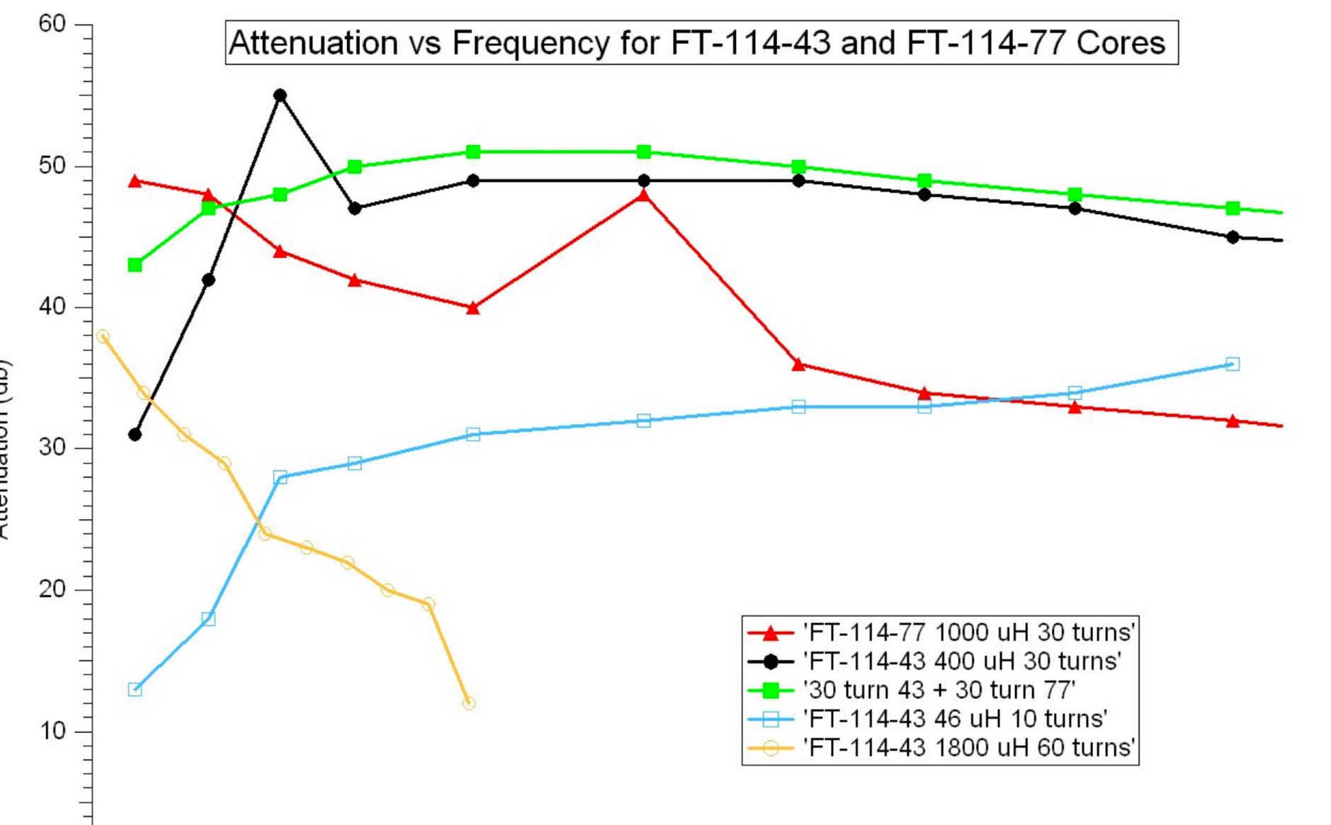 Common mode currents are those currents that flow in the same direction on a wire bundle, as opposed to the currents that flow
 -
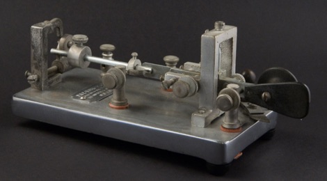 The Vibroplex Collector’s Page details the history and identification of Vibroplex semi-automatic telegraph keys, commonly known as "bugs." It traces the evolution from Horace G. Martin's 1902 Autoplex, which required a battery, to the fully mechanical Vibroplex patented in 1904. The resource explains how these keys generate automatic dots and manual dashes, helping telegraphers mitigate Repetitive Motion Disorder (RMD) and increase sending speed, thus improving their earnings. The site also covers the initial design by Alfred Vail in 1844, Jesse Bunnell's 1881 "Triumph Key," and William O. Coffe's 1904 "Mecograph." This page assists owners in identifying their Vibroplex models and determining their manufacturing dates, providing insights into the company's long history and notable figures like J. E. Albright. It notes that approximately 300,000 Vibroplexes have been produced since 1904, with the Original model still in production after more than 90 years. The resource also touches upon various Vibroplex models, including unusual, scarce, and common types, alongside legal and illegal clones from other manufacturers.
 -
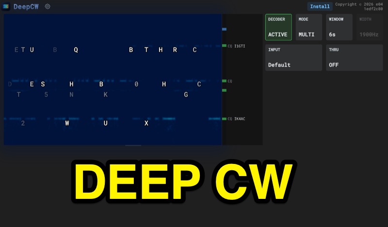 Operating in challenging RF environments, DeepCW provides real-time Morse code decoding capabilities through a neural network model. The software excels at robustly interpreting weak signals, mitigating the effects of QSB, and performing effectively in noisy conditions, a common issue for CW operators. It also supports multi-channel decoding, allowing for the simultaneous interpretation of multiple CW signals present in the audio stream. The application integrates audio pass-through functionality, enhanced with deep-learning-based noise reduction to clean up the incoming audio before decoding. Benchmarking data indicates a 0.00% error rate from 0 to -4 dB SNR, with errors remaining below 1.5% at -8 dB SNR and under 8% at -10 dB SNR across the full range of CW speeds. The project provides comparative analyses against established decoders such as _CW Skimmer_, _fldigi_, and _ggmorse_, utilizing publicly available CW QSO videos from YouTube to demonstrate its performance. DeepCW is designed for cross-platform deployment, supporting Windows, macOS, Android, and iOS operating systems. The core _DeepCW Engine_, which houses the decoding model and a reference implementation, is available separately, offering Python and Node.js examples for decoding from WAV audio files.
 -
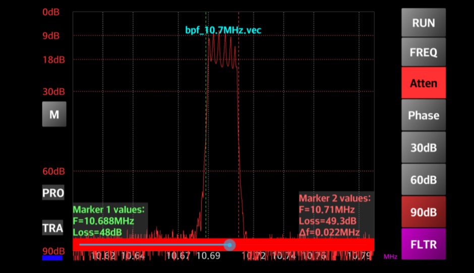 Enables Android users to operate various _miniVNA_ antenna analyzers via Bluetooth, USB, or Wi-Fi, providing a portable solution for RF measurements. The application supports full control over data acquisition, offering features like custom frequency range selection from 1 KHz to the VNA's full range, and automatic screen adaptation for diverse Android device resolutions. It facilitates intuitive, wizard-based calibration for both reflection and transmission modes, saving calibration data for different VNA types (Standard, Pro, Pro with Extender) to avoid repeated procedures. The software displays critical parameters such as SWR, |Z|, Return Loss, Phase, Rs, and |Xs| on 2-axis graphs or Smith charts, with multi-touch gestures for zoom and frequency shift. It includes a frequency generator mode with independent channels and attenuator control for the miniVNA Pro, along with a sweeper function. The cable data mode automatically calculates phase and loss, measures cable length from less than 1 meter to hundreds of meters, and includes a table of common coax cable velocity factors. An experimental X-tal mode measures resonance frequency, Rs, and Q. Data export options include CSV, ZPLOT, and S1P formats, with CSV import capability. The application also features an SM6ENG Audio mode for SWR tuning without visual reference and provides a miniVNA battery voltage indicator. It supports a wide frequency range, with the miniVNA Extender extending coverage up to **1500 MHz**. The application is compatible with Android version 2.2 and later, tested on devices like the _Galaxy TAB 7.7 P6800_.
 -
 256 memories enable the _AT-AUTO_ to recall settings across multiple bands, making it efficient for operators who frequently change frequencies. The tuner is compatible with various antennas and amplifiers, such as the Mercury LUX, and integrates seamlessly with radios like the FLEX 6400 using an RS232-USB connection. This integration allows the tuner to follow frequency changes without additional input, enhancing operational efficiency. Despite being out of production, the _AT-AUTO_ remains supported by Kessler Engineering, which offers firmware updates and repair services. The tuner features a cross-needle SWR meter, providing quick visual feedback during tuning. It also includes a QRO keyline circuit to protect amplifiers during tuning. Users appreciate the tuner's ability to track radios via CAT control, avoiding automatic tuning during QSOs, a common issue with other models. The _AT-AUTO_ is praised for its durability and performance, with many users noting its reliability over years of use. Its ability to handle legal limit power and its balanced line output make it a versatile choice for serious operators. Although it lacks some features like multiple coax outputs found in other models, its robust build and continued support make it a valuable tool for HF enthusiasts.
 -
 Clarifies the intricate process of calibrating the _Elecraft K2_ dial, addressing common user challenges and lively discussions on the Elecraft reflector. Wilhelm, W3FPR, dissects the K2's PLL synthesizer design, chosen for its low phase noise, kit-friendly duplication, and cost-effective components. The resource emphasizes the critical role of the 4000.000 kHz reference oscillator's accuracy during CAL PLL, CAL FIL, and CAL FCTR functions, noting its dependence on temperature and crystal stability for optimal performance. Explaining the K2's frequency display, the document reveals it relies on microprocessor-driven look-up tables generated by CAL PLL for VFO values and CAL FIL for BFO values. In SSB and RTTY, these combine, while CW and CWr modes also factor in the sidetone pitch. The author details inherent limitations, such as the 10 Hz increment resolution of the dial and varying PLL step sizes—from 3 Hz on 160 meters to 10 Hz on 10 meters. BFO increments range from 20 to 35 Hz, collectively limiting practical dial accuracy to within **20 Hz** with diligent effort, or **30 Hz** for a slightly less demanding task. The guide outlines a four-step calibration procedure: setting the reference oscillator, running CAL PLL, running CAL FIL, and setting all BFOs. It highlights the _N6KR Method_ as a particularly easy and accurate approach, requiring only the K2 and a known frequency source like WWV for zero-beating, eliminating the need for external test equipment.
 -
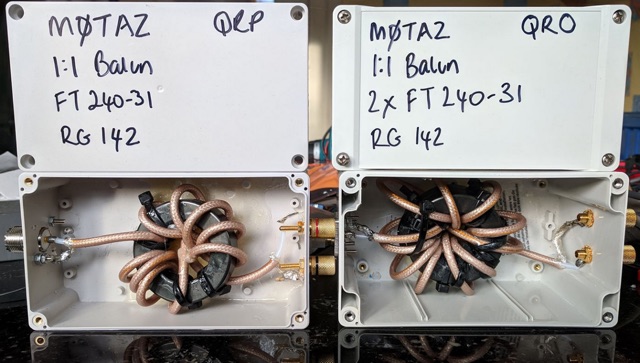 If you want to build your own common mode choke, this article explains how to measure the efficiecy of your choke before using it. In the examples has been used Amidon FT240-31 toroids.
 -
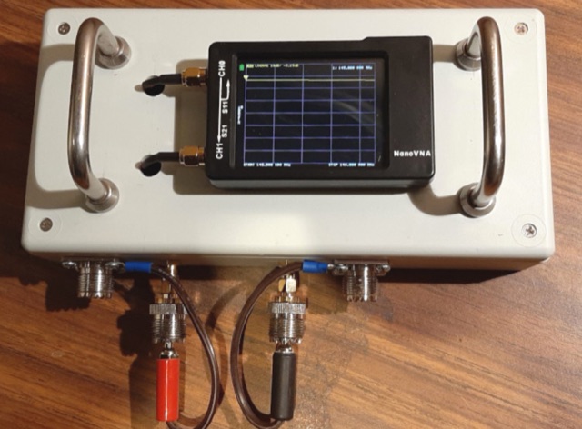 How many times have you heard the advice to coil a few turns of coax at the antenna end to form a choke. How to find out if your common mode current choke really works
 -
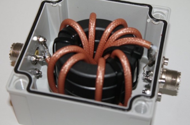 Home brewing a high performance, high power common mode choke for HF bands
 -
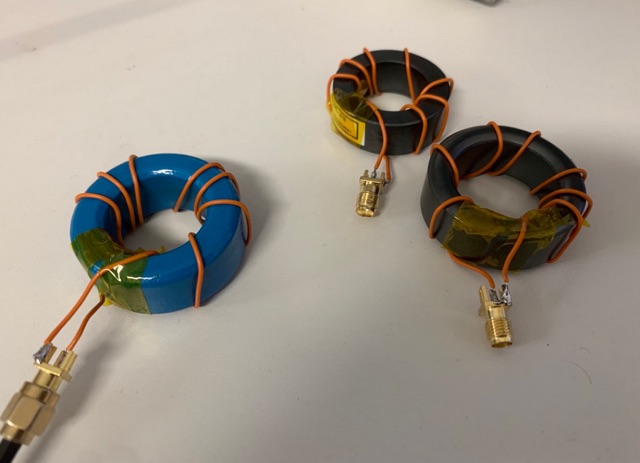 Finding the the best ferrite material for a common-mode choke. How to create efficient ferrite cores and how to measure them