Search results
Query: how to use an antenna an
Links: 135 | Categories: 0
-
 Small antenna, what causes loss and how to increase radiation resistance in small antennas., A description of loss and radiation resistance.
 -
 Mitigating RF noise in a mobile operating environment, particularly within a _Jeep TJ_ vehicle, presents unique challenges due to the vehicle's electrical system and chassis characteristics. This resource details practical methods for identifying and suppressing various forms of radio frequency interference (RFI) that can degrade receiver performance for both CB and amateur radio transceivers. It covers common noise sources such as ignition systems, alternators, fuel pumps, and computer modules, explaining how these components generate broadband or specific frequency noise that impacts radio communications. The guide offers actionable solutions, including proper grounding techniques, the strategic use of ferrite beads and toroids on power and data lines, and the installation of bypass capacitors. It discusses the effectiveness of different filtering strategies for DC power lines and antenna feedlines, illustrating how a clean power supply and shielded cabling can significantly reduce conducted and radiated noise. The information presented helps operators achieve a lower noise floor, improving signal-to-noise ratio and enabling clearer reception of weak signals, which is crucial for effective mobile DXing or local ragchewing.
 -
 Discussion at eham about wire size used in wire antennas, and how it affects the gain of the antenna
 -
 Here you will find information on how antennas behave when stacked G/T is an important figure-of-merit for the antenna's overall receive performance, because it balances forward gain (G) against received thermal noise (T).
 -
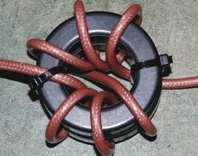 May 2015 Radcom Article on common-mode chokes that can be used for control cables, phone lines, but mostly on typical HF antenna systems. This article explain what common mode chokes does, why you meay need one, properties common mode chokes should have, how to build and measure performances.
 -
 Presents the construction of a 2-meter **Skeleton Slot Yagi** stack, detailing the design process and practical considerations for VHF operation. The author shares insights from building and testing this antenna, emphasizing its performance characteristics for local and extended range contacts. The project outlines the specific dimensions and materials used, providing a clear path for other radio amateurs to replicate or adapt the design for their own stations. The resource covers the unique aspects of the Skeleton Slot radiator, explaining how its geometry contributes to gain and pattern control. It includes discussions on impedance matching and feedline considerations crucial for optimizing power transfer and minimizing SWR. The article draws on real-world testing, offering practical results that validate the theoretical design. This project serves as a valuable reference for those interested in custom VHF antenna solutions.
 -
 The **Solarcon A99** vertical antenna, a half-wave over a quarter-wave variable mutual inductance design, primarily serves the 11-meter CB band but also finds use on 10 and 12 meters for amateur radio operators. Its simple construction, consisting of three fiberglass sections and a 16 AWG radiating element, makes it an accessible option for new operators or those seeking an easy-to-install base station antenna without complex mounting requirements. Despite claims of 9.9 dBi gain being widely considered exaggerated, and a manufacturer rating of 2000 watts power handling often viewed with skepticism (with 300 watts suggested as a practical limit), the A99 maintains popularity due to its low cost and ease of deployment. It typically tunes to a 1.2-1.3 SWR out of the box, requiring minimal adjustment via its two tuning rings. Its high angle of radiation allows for effective local communication even when mounted at low heights, such as 8-10 feet off the ground. However, the A99 is known for significant RF bleed-over issues, particularly when operated with higher power or mounted close to residential electronics. While its internal design is often described as cheap, the antenna exhibits remarkable durability, frequently lasting a decade or more in various weather conditions. Its affordability and straightforward setup continue to make it a go-to choice for many radio enthusiasts.
 -
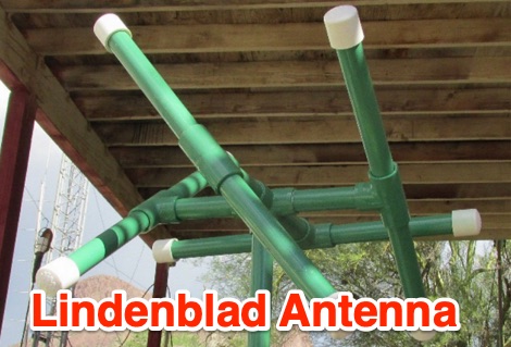 This is a presentation used at OVARC on the LindenBlad antenna construction. The presentation cover several topics about this antenna, from the basic antenna design, to the guide on how to contruct a custom lindenblad antenna for the 2 meters band and and 70 centimenters band.
 -
 6m/2m/70cm Yagi Antenna Built from Old TV Antenna This turned out to be a great little antenna. It works the 6 meter, 2 meter and 70 centimeter bands. You can use one common feedpoint or two seperate feedpoints depending on how you would like to connect this antenna to your transceiver.
 -
 This kind of antenna has grown in popularity over the last years because it gives you a decent performance and triband capabilities. But its 50 MHz design is far from optimal. Here you can learn how to improve its 50 MHz performance in a very easy way.
 -
 The **TransWorld Antennas TW2010 Traveler HF Portable Vertical Antenna** assembly video provides a visual walkthrough for deploying this popular portable HF antenna. It details the step-by-step process, from unpacking components to final setup, which is crucial for operators preparing for field day operations or DXpeditions. The video focuses on practical aspects, showing how to connect the various elements and secure the antenna for optimal performance. Operators often seek clear assembly instructions for portable antennas like the TW2010 to ensure quick and correct deployment in diverse environments. This visual aid helps clarify potential ambiguities found in written manuals, illustrating the proper handling of the antenna's radial system and telescopic elements. The video serves as a valuable resource for those aiming to achieve efficient operation with the **TW2010 Traveler** in a portable setting. Understanding the assembly sequence can significantly reduce setup time and prevent common errors encountered during initial deployments.
 -
 Demonstrates the swift setup process for a **Trans World Antenna**, showcasing its utility for portable amateur radio operations. The video highlights the antenna's design for quick deployment, a critical factor for activations like Summits On The Air (SOTA) or Parks On The Air (POTA), where efficiency in establishing a station is paramount. It illustrates the physical components and the sequence of assembly, emphasizing ease of use in varied field environments. The antenna system is presented as a multi-band solution, capable of operating across various HF frequencies. This adaptability makes it a versatile choice for hams engaging in outdoor activities or emergency communications. The visual demonstration provides practical insights into managing the antenna elements and feedline for optimal performance during temporary deployments. The focus remains on the practical aspects of field setup, rather than detailed technical specifications or performance metrics.
 -
 KB9AMG's Top WSPR Spots presents a focused online tool for monitoring **2-way WSPR reports**, specifically detailing propagation data from February 2026 through March 2026. This resource aggregates _WSPRnet_ data, allowing radio amateurs to observe weak signal propagation conditions across various bands. The interface is straightforward, presenting callsigns, frequencies, signal-to-noise ratios, and distances for each reported contact, which is crucial for understanding current band openings and signal paths. The utility of this WSPR spotter lies in its ability to quickly visualize global propagation. Users can identify active stations and assess signal viability over long distances, with reports often showing contacts spanning thousands of kilometers. For instance, a typical WSPR report might indicate a signal from Europe reaching North America with a _SNR_ of -25 dB, demonstrating effective low-power communication. This data is invaluable for planning DX operations or evaluating antenna performance under actual propagation conditions.
 -
 Operating a ham station often involves encountering radio frequency interference (RFI), RF feedback, or RF burns, which are frequently misattributed to poor equipment grounding. This resource meticulously dissects these assumptions, asserting that RF grounds on the operating desk often merely mask more significant system flaws. It identifies five primary causes for RF problems, including antenna system design flaws, proximity of the antenna to the operating position, DC power supply ground loops, equipment design defects, and poorly installed connectors or defective cables. The content emphasizes that issues like "hot cabinets" or changes in SWR when connecting a ground indicate substantial RF flowing over wiring or cabinets, a phenomenon known as common-mode current. The article provides detailed explanations of common-mode current generation, particularly from single-wire fed antennas like longwires, random wires, and OCF dipoles, which inherently present high levels of RF in the shack. It also illustrates how vertical antennas, lacking a perfect ground system, can excite feed lines with significant common-mode current. Through simulations, the author demonstrates how a dipole without a proper _balun_ can cause RF problems at the operating desk, showing current patterns and voltage distributions on feed line shields. The discussion extends to the proper application of _RF isolators_ and _ferrite beads_, clarifying their role in modifying common-mode impedance on cable shields and cautioning against their use as a band-aid for fundamental system defects. The resource advocates for correcting the actual source of RF problems, such as antenna system issues or poor connector mounting, rather than relying on internal shack grounding or isolators. It highlights that properly functioning two-conductor feed lines, like coaxial or open-wire lines, should result in minimal RF levels at the operating position, even without a desk RF ground. The author shares personal experience, noting that his stations since the late 1970s have operated without RF grounds at the desks, relying instead on proper antenna system design and feed line integrity.
 -
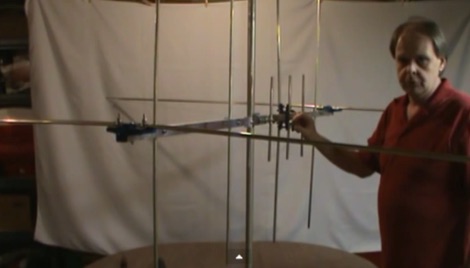
 A presentation of the Yagi Antennas, and other interesting tid-bits by Brian Mileshosky. The document provides an in-depth exploration of the Yagi-Uda antenna, detailing its historical development, design principles, and performance characteristics. Originally described in the 1920s, the Yagi antenna features a driven element and parasitic elements, including reflectors and directors, which collectively determine its behavior. The document highlights how element lengths, diameters, and spacing influence gain, impedance, and directivity. It also discusses the antenna's reciprocal nature and presents data on typical gain values for various element configurations. Additionally, the text covers practical considerations, such as the construction of a "Tape Measure Yagi" for amateur use, and touches on related antenna types like dipoles and their application in Near Vertical Incident Skywave (NVIS) communication.
 -
 Investigates the legal framework surrounding **pneumatic antenna launchers** in Victoria, Australia, specifically their classification under the Firearms Act 1996. The author, VK3KBC, details how these devices, designed to discharge a projectile by compressed air, are defined as 'firearms' and subsequently categorized as **Category E Longarms**. This classification carries significant penalties for unregistered possession or use, with the author noting the lack of provisions for amateur radio operators to legally possess and use such devices for antenna deployment. The author shares personal experiences needing such devices for portable HF radio operations, contrasting them with previously legal slingshots and current alternatives like kites or bow and arrow. VK3KBC outlines efforts to advocate for legislative change, including submissions to the Wireless Institute of Australia (WIA) and the Victorian Department of Justice, proposing an amendment to Section 3(i) of the Firearms Act 1996 to include amateur radio field operations as an exempted use. The resource also reviews the original intent of the Category E firearm classification, suggesting that pneumatic antenna launchers may have been assigned this category in the absence of a more suitable alternative.
 -
 Constructing a compact directional antenna for the 17-meter band, this resource details the build process for a Moxon rectangle, a two-element Yagi variant with folded-back elements. It covers the antenna's evolution from the _VK2ABQ beam_ and provides specific dimensions for a version built using fishing pole whips. The content includes a discussion of the antenna's radiation pattern, feedpoint impedance, and its inherent front-to-back ratio, which is often superior to a standard two-element Yagi. Practical considerations for element spacing and material choices are also addressed, alongside a visual representation of the antenna's physical layout. Performance data presented includes a comparison showing the Moxon rectangle's **2.5 dB gain** over a half-wave dipole and a front-to-back ratio of **20 dB**. The resource also touches upon the antenna's relatively wide bandwidth for a two-element beam and its suitability for portable operations due to its compact footprint. It offers insights into optimizing the design for specific operating conditions and discusses the advantages of its lower take-off angle compared to omnidirectional wire antennas, making it effective for DX contacts on the 17-meter band.
 -
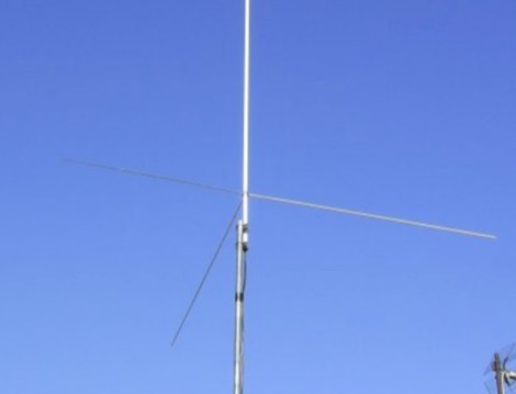
 Such kind of omnidirectional antenna gives the possibility to be QRV with horizontal polarisation, as commonly used for the CW and SSB section of the 2m band. This actual design shows a 1.3:1 bandwidth of about 150kHz, centered to 144.200MHz.
 -
 137 kHz propagation analysis details ground wave and sky wave mechanisms, drawing heavily from **CCIR Rec. 368-6** for ground wave field strength predictions and **CCIR Rep. 265-7** for sky wave modeling. The resource presents field strength values for 1 W ERP at varying distances, considering ground conductivity and permittivity for ground wave, and ionospheric height (70km daytime, 90km nighttime) for sky wave. Key factors like ionospheric focusing (factor "D"), reflection coefficient ("RC"), and antenna ground pattern factors ("Ft", "Fr") are quantified for 137 kHz, enabling calculation of sky wave field strength. Practical coverage ranges are derived for 137 kHz, showing useful ground wave coverage up to 1600 km over seawater and 1100 km over average ground, assuming a -9 dBuV/m noise floor. Sky wave coverage extends beyond 2200 km during night-time and winter daytime, but is negligible during summer daytime at solar minimum. The document also compares ground wave and sky wave strengths, identifying crossover distances at 550 km (night-time), 750 km (winter daytime), and 1250 km (summer daytime), where interference fading can occur. Adjustments for solar maximum conditions are provided, indicating 2-11 dB higher sky wave values depending on distance and season.
 -
 A page describing how to home made a custom 9:1 balun for a common portable wire antenna. The author suggest to use 4C65 or FT140-61 toroids instead of the common Amidon T200-2
 -
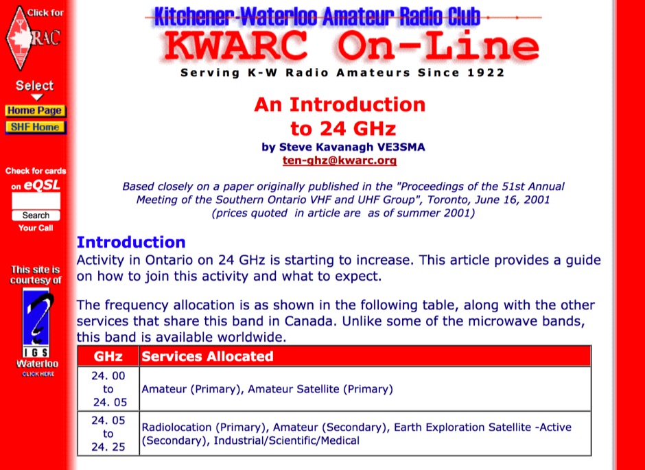 Article provides a guide on how to use 24 GHz band and what to expect, including Active modes, equipment, propagation and antennas for this band in by VE3SMA
 -
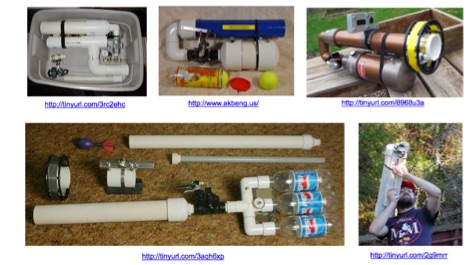
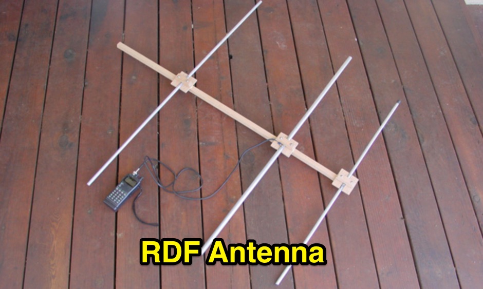 How to homemade antenna to be used with a handheld on the aircraft band to locate noise sources
 -
 1500 watts PEP SSB is the power handling capability of the MFJ-989C HF Antenna Tuner, a popular choice among amateur radio operators. Users have shared a wide range of experiences, with some praising its durability and performance over decades of use, while others criticize its build quality and accuracy. The tuner features a built-in dummy load, SWR-wattmeter, and a balun for balanced line feeders, making it versatile for various antenna setups. However, discrepancies in RF power readings and SWR measurements have been noted, with some users finding the dual scale meter to be off by about 20% compared to a Bird wattmeter. Long-term users report that the MFJ-989C performs well with proper antenna setups, but caution against tuning at high power without initial adjustments at lower power levels. Some have experienced issues such as arcing when exceeding 400 watts, while others have had no problems even at higher power levels. The roller inductor and capacitors are functional, though some users have had to perform maintenance like tightening screws or cleaning components to ensure reliable operation. Despite mixed reviews, the MFJ-989C remains in production, suggesting continued demand. It's a tuner that requires careful handling and possibly some DIY fixes to achieve optimal performance.
 -
 Examines Radio Frequency Systems (RFS), a manufacturer specializing in high-performance cable solutions for diverse communication infrastructures. The company, with over 120 years of heritage, focuses on designing and producing robust, long-life connectivity systems, including _low loss foam dielectric RF cable_ and _premium radiating cable_. RFS's product range supports critical applications in cellular networks, microwave antenna systems, and specialized installations within buildings and tunnels. The resource highlights RFS's commitment to innovation, addressing emerging industry standards like _FRMCS_ for railway communication and advanced fiber solutions for data centers. It also details the company's manufacturing capabilities in Hannover, Germany, emphasizing the quality and reliability associated with _Made in Germany_ products. The content covers various connectivity landscapes, from urban solutions for connected cities to private 5G credentials and future plans. Specific product categories include _fiber, power & hybrid cable_, and _low loss high power air dielectric RF cable_, showcasing their broad portfolio for complex RF environments.
 -
 In this article, author examine stresses placed on common-mode chokes (aka baluns) as hams use/abuse them, examine the efficiency of simple dipole multi- band antennas and their feed systems. Stressing a Balun.
 -
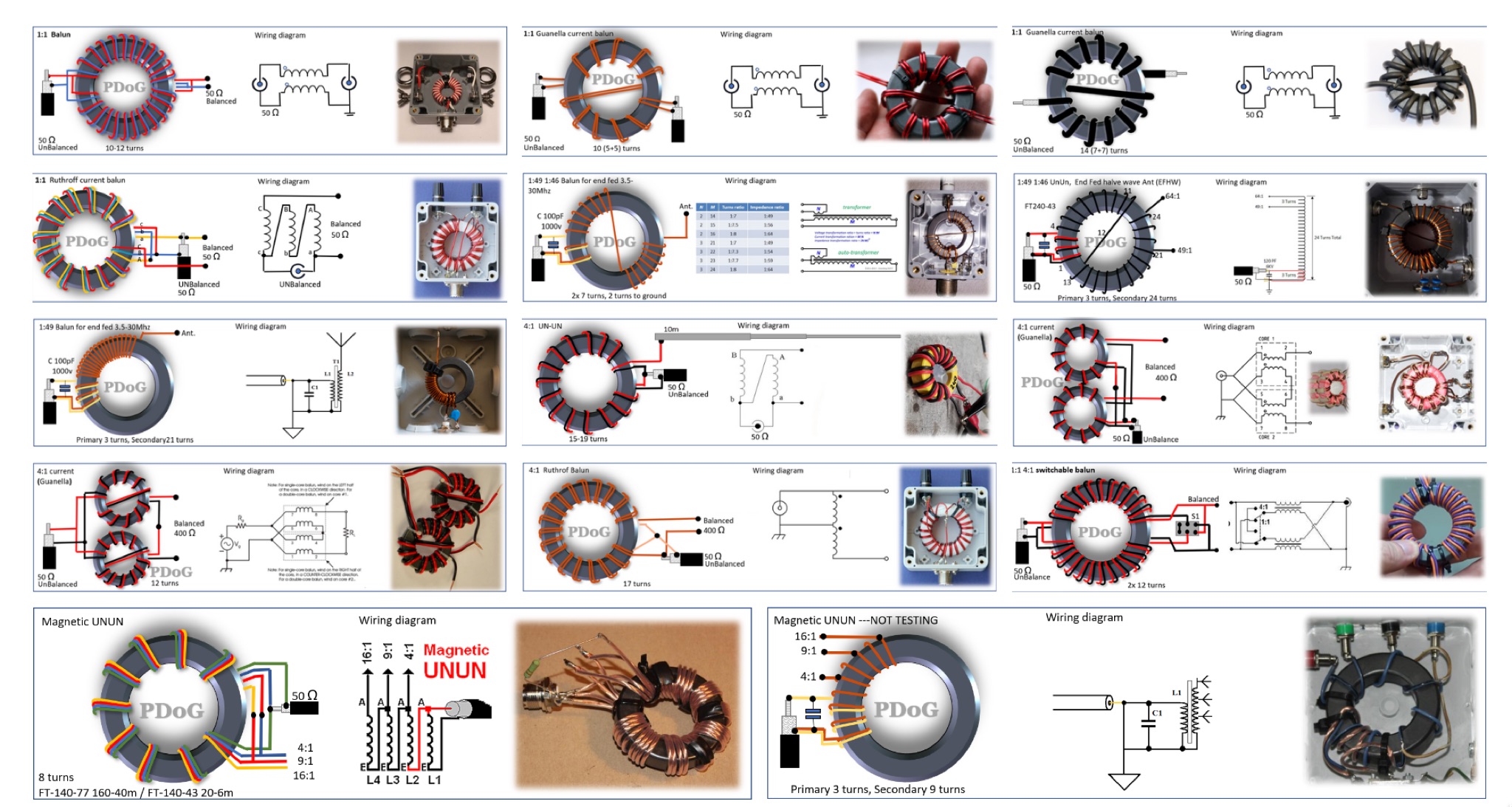
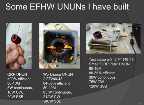 A very well done presentation about End-Fed Half-Wave antennas. This PDF document contains a summary of experiences in how to build custom EFHW antennas. Includes an interesting comparison table of UnUn configurations with recommended toroids, Wire size, turns and capacitors. An useful recap on common errors in building homebrew EFHW Ununs completes the document.
 -
 Presents a personal blog, "QSL, maraca!", maintained by Luiz Belem, PY1UR, detailing his amateur radio endeavors. The content includes posts on station setup, operating experiences, and general ham radio topics, reflecting the perspective of an active DXer and contester. The blog serves as a digital logbook and platform for sharing insights with the amateur radio community. Documents PY1UR's participation in various on-air activities, showcasing his QSL card collection and providing narratives behind specific contacts. It offers practical insights into antenna configurations and radio equipment used, demonstrating effective strategies for achieving **DX contacts** and improving station performance. The blog's entries provide a historical record of PY1UR's _amateur radio journey_.
 -
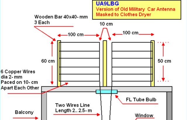 The antenna almost repeat the design of the Car Antenna however instead of aluminum tubes it was used copper wire in plastic insulation in diameter of 2- mm (12 AWG).
 -
 Sixty-meter repeaters typically use a 1 MHz frequency separation between input and output, while 2-meter repeaters commonly employ a **600 kHz** split and 70-centimeter repeaters use a **5 MHz** offset. This article details the fundamental technical principles of amateur voice repeaters, explaining how they extend VHF/UHF communication range by receiving on one frequency and simultaneously retransmitting on another. It covers essential components such as receivers, transmitters, filters, and antennas, often situated on elevated locations for optimal coverage. The resource delves into the critical challenge of _desensing_—where the repeater's strong transmit signal overpowers its own receiver—and the engineering solutions employed, including antenna separation and the use of high-Q cavity filters. It also explores various control and timing systems, from basic squelch activation to more sophisticated microcontroller-based boards that manage functions like voice identification, time-out timers, and fault protection. Different access methods are discussed, including open access, toneburst, CTCSS subtone, and DTMF, each offering distinct advantages for managing repeater usage and mitigating interference. Furthermore, the article examines repeater linking, both conventional RF methods and modern internet-based solutions, highlighting how linking expands coverage and promotes activity across multiple repeaters or bands. It introduces less common repeater types such as 'parrot' repeaters, which use a single frequency and digital voice recording, and linear translators, capable of relaying multiple signals and modes simultaneously across different bands, often found in amateur satellites.
 -
 Showcasing innovative RF solutions, Hofi Hochfrequenztechnik manufactures high-quality _antennas_ and RF switches. Their products, including the **versatower** and **fritzel** brands, cater to both casual operators and serious DXers. With a commitment to performance, Hofi's offerings enable operators to achieve optimal signal gain and reliability in various conditions. The company's expertise in antenna design ensures that users can effectively communicate across _HF_ bands, enhancing their overall operating experience. Whether setting up a new station or upgrading existing equipment, Hofi provides essential tools for successful ham radio operations.
 -
 This is a standard calculation method that can help you while tuning dipole antennas, by adjusting wire lengths. This method can be used also when you need to add lenght to your wires, and can be additionally used to quarter waves vertical antennas
 -
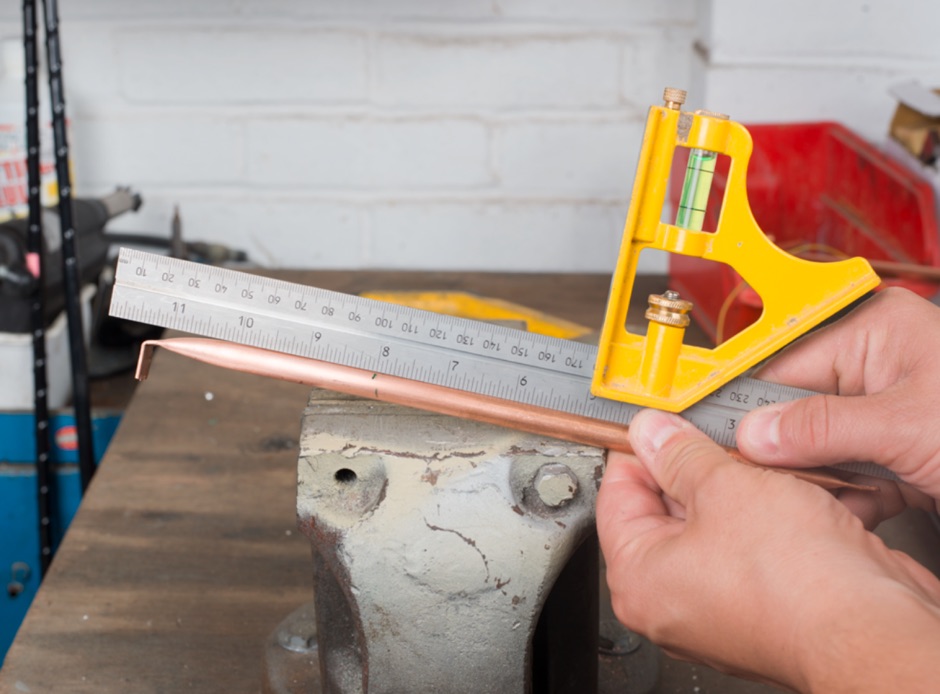 Article and video showing a technique to straighten Microbore copper pipe that is useful in antenna construction. This technique has been implemented to build a Quadrifiliar Helix antenna.
 -
 Documents the operational experiences and technical insights of amateur radio station VA3STL, offering a firsthand account of various on-air activities and equipment. The blog features a detailed narrative of a **QRP transatlantic QSO** on 12m SSB, achieving a 55 report with 10W to a mobile station in Italy using a homebrew 90ft doublet antenna. It also introduces the _Ten-Tec 539_ QRP HF transceiver, a 10W output rig covering 80m through 10m, designed for portable operations and featuring DSP and dual VFOs. The resource also delves into historical radio technology, specifically the "Gibson Girl" survival radio, an emergency transmitter operating on 500kHz (and later 8280/8364 kHz) with a hand-cranked generator and kite-deployed antenna. This section explores its origins from German designs and its use during World War II, including its distinctive curved shape for ergonomic hand-cranking. Further historical content includes a visit to Signal Hill in St. John's, Newfoundland, commemorating Marconi's reception of the first transatlantic radio signal in 1901. The post describes the Cabot Tower exhibit and the VO1AA station, highlighting the site's significance despite the thick fog during the visit. It also showcases a homebrewed _Marconi-style straight key_ by WB9LPU, crafted to celebrate the centenary of Marconi's achievement.
 -
 Over 150 pages of content are dedicated to maximizing activity on the 6-meter band, often referred to as the _Magic Band_. The resource details various propagation modes, including sporadic E, F2, and tropospheric ducting, providing insights into their characteristics and how to leverage them for DX contacts. It also covers essential equipment considerations, from transceivers and transverters to specific antenna designs optimized for 50 MHz operation, such as Yagis and Moxon antennas. The eBook presents strategies for participating in 6-meter contests and pursuing awards like _VUCC_, offering practical advice on logging software and operating techniques. It includes discussions on software tools useful for predicting propagation and managing contacts, alongside guidance on finding and utilizing DX maps to identify openings. The author, K5ND, shares his extensive experience to help operators achieve successful 6-meter DXing. Specific sections address the code of practice for 50 MHz operations and provide assistance in locating rare DX opportunities. The content is structured to guide both new and experienced operators through the nuances of the band, from initial setup to advanced operating strategies.
 -
 Meet The Breakers is a unique exploration of the CB radio culture in the United Kingdom, hosted by Colin The Head. This series delves into the lives of various CB radio enthusiasts, showcasing their setups, stories, and the vibrant community surrounding this hobby. Each episode features interviews with notable figures in the CB world, providing insights into their experiences and the equipment they use. The program not only highlights the technical aspects of CB radio, such as antennas and signal checks, but also captures the personal stories that make this hobby special. From collectors of rare equipment to modern-day users navigating the airwaves, Meet The Breakers offers a comprehensive look at the diverse personalities that contribute to the CB radio landscape in the UK. Whether you're a seasoned operator or new to the scene, this series is a valuable resource for anyone interested in the world of CB radio.
 -
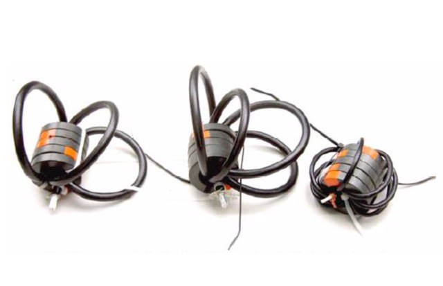
 This page provides a detailed guide on the Guanella Current Balun for ham radio operators. The author shares very nice schematics, photos, and explanations on the construction and use of this type of balun. The content explains when a balun is needed and how it can help with common-mode currents in antenna systems. It also discusses the construction process, including winding the balun around a ferrite core. This resource is useful for hams looking to improve their antenna systems and reduce common-mode currents for better performance. This article is in Dutch.
 -
 The DIY 137 MHz WX SAT V-dipole antenna project details the construction of a specialized antenna for receiving weather satellite transmissions. It provides specific dimensions for the dipole elements, designed for optimal reception around the 137 MHz band, which is commonly used by NOAA and Meteor weather satellites. The resource outlines the materials required, such as aluminum tubing for elements and PVC for the support structure, along with the necessary coaxial cable and connectors. The article presents a clear, step-by-step assembly process, including how to form the V-shape and connect the feedline. It emphasizes practical considerations for mounting and weatherproofing the antenna for outdoor deployment. The design focuses on simplicity and effectiveness for amateur radio operators interested in satellite imagery. Key aspects include the precise angle of the V-dipole and the lengths of the radiating elements, which are critical for achieving the desired circular polarization response for satellite signals. The resource includes photographic documentation of the construction phases and the final mounted antenna.
 -
 This article demonstrate how to build and mount a 40 meter loaded dipole using basic materials. This antenna reduce the overall length of an HF dipole through the use of loading coils.
 -
 This type of antenna is a popular antenna design as the performance is very good across the HF bands and requires little or no tuning. It’s a dipole fed off center with a 4:1 balun at the offset feed point. The antenna shown covers 80, 40, 20 and 10 meters. The formula can also be used to adjust the overall length to cover more or fewer bands and the resulting overall length. 160-10m, 80-10m or 40-10 meters depending on your available space. Other bands will require a tuner.
 -
 How to solve RFI problems caused by the charge controller, which is a PWM type charge controller, that generates a lot of EMI interference
 -
 Collection of several topics on antenna tuners and their performance. Why use an antenna tuner? How does an antenna tuner…tune Does an antenna tuner fool the radio? Will an antenna tuner waste power? Can an antenna tuner help get more power to the antenna?
 -
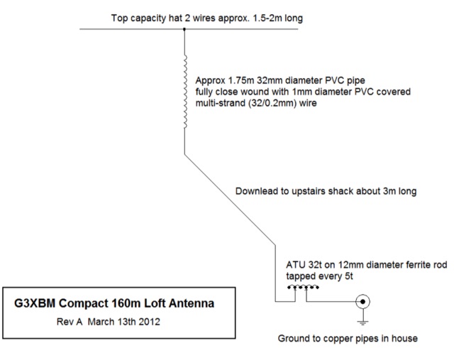 This is a very small vertical 160m antenna that fits in the loft of even my small house. It was built as a way of getting a signal out on 160m for local AM contacts, but the local noise level was far too high to allow it to be used at night for this purpose. However, on WSPR it did a pretty good job with WSPR spots from a very long way across Europe being received when running 2.5W out.
 -
 The Bazooka antenna, a coaxial dipole, functions as an omnidirectional antenna with vertical or horizontal polarization. Patented in 1939 and refined in 2006, it features a quarter-wavelength coaxial cable with separated conductors. The outer conductor connects to a sleeve, while the inner conductor extends vertically. Initially complex, it has been simplified for versatile use, including military applications. Adding elements can modify its behavior for NVIS or Yagi-Uda configurations. Experiments in 2007 at the Campus de Pesquisas GeofÃsicas in Paula Freitas-PR demonstrated consistent VHF and UHF performance, showing reliable return loss measurements despite variable weather.
 -
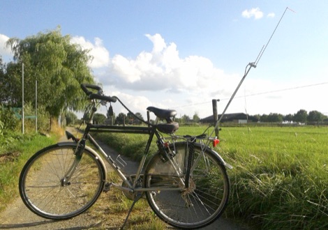 Homebrewing a UHF antenna to be used on a bicycle. This simple project gives you the right hints on how to build and setup and install a 70cm antenna on a bicycle.
 -
 This article shares the author's experience with building antennas. After putting a large magnetic loop project on hold, they decided to try a base-loaded vertical antenna. The author explains how they chose to design a new antenna from scratch, aiming for a frequency of 7 MHz. They describe the calculations needed to find the right coil inductance and how they used 3D-printed parts for the construction. The article wraps up with results from their initial tests, showing good communication on different bands and highlighting the success of their design.
 -
 A coaxial cable trap is a fundamental component in multiband antenna design, enabling a single radiator to resonate efficiently on multiple frequencies by electrically shortening or lengthening the antenna element. This project focuses on constructing such a trap for a vertical antenna operating on the 10 MHz (30m) and 14 MHz (20m) amateur bands, providing practical insights into its fabrication and integration. The article outlines the specific dimensions and winding techniques for the coaxial trap, emphasizing the use of readily available materials. It details the physical construction of the vertical element, including the mast and radiating sections, to achieve optimal performance across both target bands. The author shares personal experiences with similar trap designs, noting their effectiveness in previous horizontal dipole configurations. Key construction steps are illustrated with _original photos_, showing the assembly of the trap and its incorporation into the overall antenna structure. The design aims for a compact footprint, making it suitable for limited space installations while still delivering effective DX capabilities on the **30-meter** and **20-meter** bands.
 -
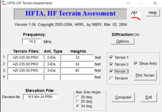 A complete guide to plan antenna installation by using several tools and resources including the popular HFTA High-Frequency Terrain Assessment software distributed by ARRL. A full tutorial on how to use it and how to interpretate reports produced by this antenna setup analysis tool.
 -
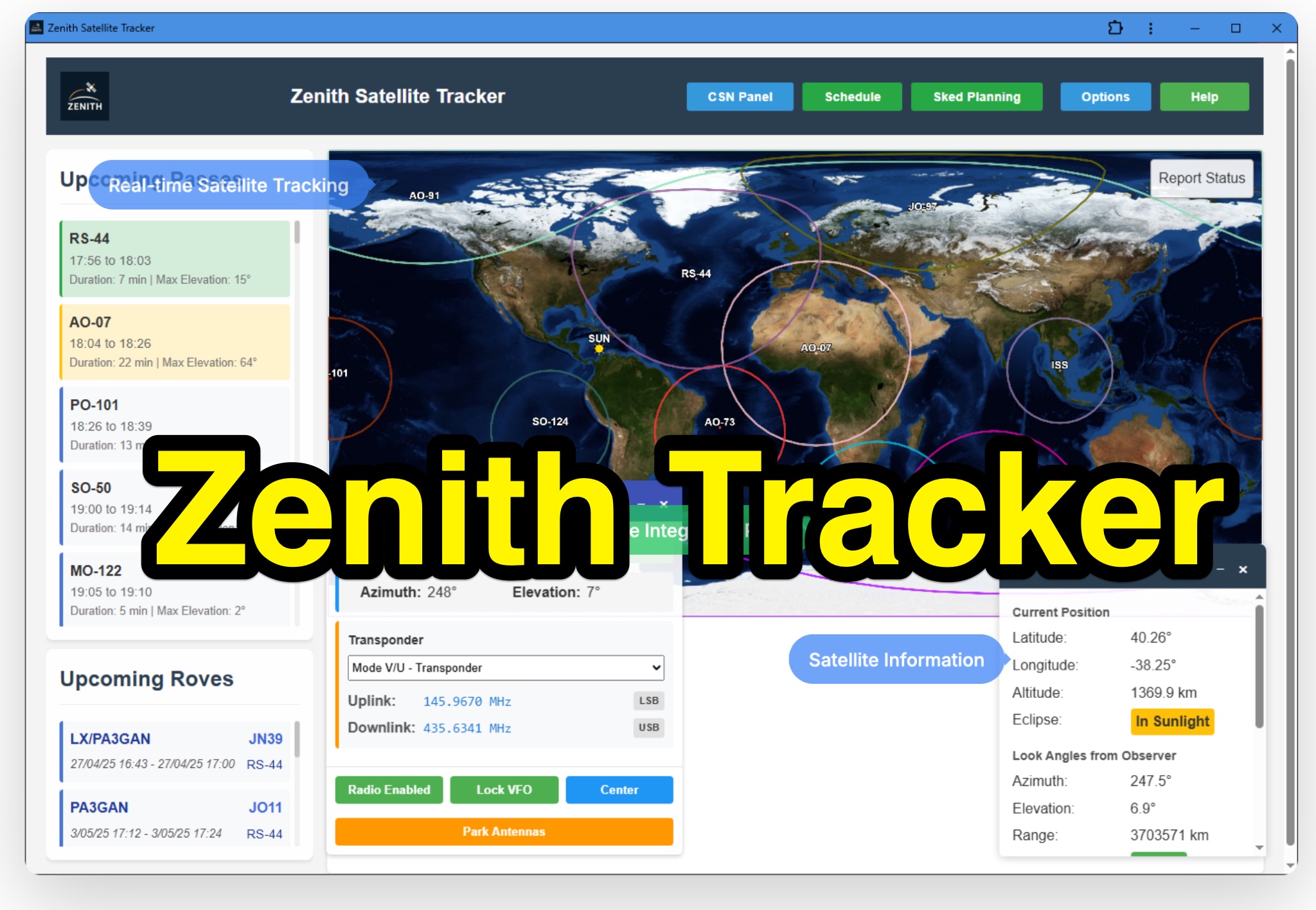 Zenith Tracker offers real-time satellite tracking, pass predictions, and radio hardware integration for ham radio operators. The platform includes an interactive world map showing satellite positions, footprints, and ground tracks, as well as a polar radar visualization for detailed pass analysis. Users can view upcoming passes, set filters, and receive notifications. Integration with CSN Technologies S.A.T Hardware and QTRigDoppler allows for automatic radio control, antenna tracking, and transponder management. The platform also offers APRS message interface, grid square-based location input, and API integration for rover activations. Zenith Tracker is recommended for both general users and those needing advanced hardware integration.
 -
 Modeling an antenna over real terrain gives you a visual picture of how terrain impacts performance. You can use a model to determine optimum height for antennas on an existing tower, Compare different tower locations for performance, Compare different sites for performance
 -
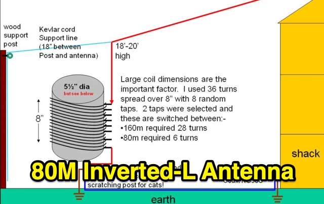 80m Inverted-L Antenna, Base-loaded for 160m antenna. This antenna is not a good DX antenna however within small garden where true DX antennas would be impossible it has performed very well.