Search results
Query: impedance ratio
Links: 128 | Categories: 0
-
 Protecting amateur radio equipment from transient overvoltages requires robust lightning and surge protection, which is the focus of Electronic Specialty Products. The company provides various devices, including coaxial lightning arrestors for antenna feedlines and surge protectors for AC power lines and data circuits. These devices are engineered to divert high-energy surges, such as those caused by direct or indirect lightning strikes, away from sensitive transceivers, amplifiers, and computer components, thereby preventing catastrophic damage. Key products include the _Coaxial Lightning Protector_ series, designed for various impedance levels and frequency ranges up to 3 GHz, and the _AC Line Surge Protector_ for shack power distribution. Effective deployment of these protection devices can significantly reduce the risk of equipment failure and ensure operational continuity during severe weather. For instance, a properly installed coaxial arrestor can handle peak currents of **20 kA**, while AC line protectors offer clamping voltages typically below 400V. Comparing different models reveals varying levels of insertion loss and return loss, with some coaxial units exhibiting less than 0.1 dB loss at 500 MHz, making them suitable for high-performance HF and VHF/UHF operations. Integrating these components into a comprehensive grounding system is crucial for achieving maximum protection against both common-mode and differential-mode surges.
 -
 This web article by VK3BLG details the construction of an experimental 70cm (432 MHz) circularly polarized patch antenna, intended for satellite communication. The resource provides dimensions, feed point specifications, and impedance matching considerations for a single patch element, with discussion extending to array configurations for circular polarization. Construction involves a copper patch element on a dielectric substrate, fed via a coaxial cable. The design is based on information derived from AO-40 satellite antenna specifications, focusing on achieving circular polarization for satellite reception. The article includes specific dimensions for the patch and feed points, along with impedance values. Validation is implied through on-air satellite reception reports, with initial signal reports of **1 S-point above noise** for AO-40 beacons using a grid reflector, improving to **3-4 S-points above noise** with a 2-turn helical feed. The author references a _NanoVNA_ for impedance measurements and discusses the relationship between slot and dipole antennas in the context of patch design. DXZone Focus: Web Article | 70cm Patch Antenna | On-Air Satellite Reception | Circular Polarization
 -
 Designing and constructing portable wire antennas for HF operations, this resource explores several configurations including the _foldback dipole_ for space-constrained setups and an inductively shortened dual-band dipole for 20m and 40m. It details the calculation of inductance for shortened elements, providing a Visual Basic 6.0 program screenshot that illustrates determining coil parameters like turns and length for a **25.5 uH** inductor. The document emphasizes practical considerations such as adjusting wire lengths for optimal SWR, noting that a dual-band dipole achieved SWR below 2:1 on both 20m and 40m, with careful adjustment bringing it under 1.5:1. Further, the resource describes a half-wave antenna matched with a coaxial stub, a method often referred to as the _Fuchskreis_ in German amateur radio circles, to transform the high feedpoint impedance to 50 Ohms. This monoband solution, for a 20m application, uses a stub length of **2.98m** (0.216 lambda multiplied by coax velocity factor) and a shorted stub of approximately 48cm. The coaxial stub design is highlighted for its resilience to ground proximity, allowing it to be rolled up or laid on the ground with minimal SWR impact, making it highly suitable for portable QRP operations.
 -
 With the view to establish a quick and easy multi-band antenna deployment for portable and camping operations a simple long wire antenna with an earth or earth plus counterpoise arrangement with a 9:1 voltage unun including a tuner or simply with a tuner is one possible solution. With the 9:1 voltage unun and wire lengths suggested in the below tables the antenna should present non extreme impedances for all HF amateur band frequencies. This page is far from complete and represents the ongoing investigation into this type of antenna. Experiments to date seem to have raised more questions than obvious answers.
 -
 Hi-Z Antennas offers specialized high-impedance receiving systems, primarily focusing on phased vertical arrays for HF reception. Their product line includes preamplifiers designed for shortened vertical antennas, featuring optimized 15dB gain and array-matched characteristics. These components are engineered to enhance weak signal reception and improve signal-to-noise ratio across the HF spectrum. The company provides controllers for managing multiple vertical elements in a phased array configuration, enabling directional reception patterns. These systems are particularly effective for mitigating local noise and interference, a common challenge in urban and suburban operating environments. Specific offerings include solutions for 160-meter and 80-meter bands, addressing the unique requirements of low-band DXing. Technical details often reference components like the 2N3866 transistor in preamp designs and discuss concepts such as out-of-band attenuation. The focus remains on optimizing receiving antenna performance through impedance matching and active amplification, rather than transmit capabilities.
 -
 Presents the construction of a 2-meter **Skeleton Slot Yagi** stack, detailing the design process and practical considerations for VHF operation. The author shares insights from building and testing this antenna, emphasizing its performance characteristics for local and extended range contacts. The project outlines the specific dimensions and materials used, providing a clear path for other radio amateurs to replicate or adapt the design for their own stations. The resource covers the unique aspects of the Skeleton Slot radiator, explaining how its geometry contributes to gain and pattern control. It includes discussions on impedance matching and feedline considerations crucial for optimizing power transfer and minimizing SWR. The article draws on real-world testing, offering practical results that validate the theoretical design. This project serves as a valuable reference for those interested in custom VHF antenna solutions.
 -
 The **136kHz Vertical Antenna** at G3YMC employs a Butternut HF2V structure, standing 10m tall. It integrates a 6.5mH loading coil to achieve resonance, with a matching transformer for impedance adjustment. The antenna's configuration includes top loading via a 12m horizontal wire, enhancing capacitive impedance. Initial measurements indicated a high impedance of around 300 ohms, necessitating a transformer for a 50-ohm match. Despite challenges with ground losses, the vertical antenna has shown improved performance in specific directions, filling nulls present in the previous loop antenna setup. The tuning remains broad, with variations due to environmental factors affecting the matching. Ongoing adjustments and comparisons with the loop antenna will continue to refine its effectiveness.
 -
 The NB6Zep Antenna, an electrically shortened 80-meter end-fed wire, addresses space constraints for low-band operation by integrating two loading coils into a 37-foot wire. This design, modeled with _EZNEC_, explores configurations like the quarter-wave sloper and inverted-L, with the latter providing a more vertical radiation pattern and practical backyard deployment. The resource details specific coil construction, recommending 21 uH coils made from _BW coil stock #3026_ or similar, and outlines wire segment lengths for optimal tuning. Performance analysis indicates a radiating efficiency of approximately 27% with good ground conductivity, resulting in a signal typically 3-4 dB down compared to a full-size quarter-wave vertical. The antenna exhibits a narrow bandwidth, around 50 kHz, due to its high Q, necessitating a tuner for broader band operation. Feedpoint impedance is low, with ground resistance playing a critical role in achieving a usable SWR. The article emphasizes the importance of an effective ground rod at the feedpoint for proper operation and tuning, suggesting an antenna analyzer for precise adjustments. It confirms the antenna's suitability for DX, citing successful contacts from Oregon to the East Coast and Hawaii on a 160-meter variant, making it a viable option for urban operators seeking low-angle radiation on 80 meters.
 -
 Presents a construction project for a 1:1 current balun, specifically detailing the _Sorbie Balun and Bottle Choke_ design. The resource outlines the winding technique, employing 4+4 turns of mini coaxial cable on a large ferrite core, and provides insights into the physical assembly. It includes specific material recommendations, such as the type of ferrite and coaxial cable, crucial for achieving the desired impedance transformation and common-mode current suppression. The content covers the practical steps involved in building the balun, from preparing the coaxial cable to securing the windings on the ferrite toroid. It also discusses the integration of the balun into an antenna system, emphasizing its role in maintaining pattern integrity and reducing RF interference in the shack. The resource offers a clear, step-by-step approach, making the project accessible for homebrewers. Illustrations and photographs accompany the text, visually guiding the builder through each stage of construction. The article concludes with performance expectations and considerations for deployment, ensuring the constructed balun functions effectively across the intended frequency range.
 -
 A presentation of the Yagi Antennas, and other interesting tid-bits by Brian Mileshosky. The document provides an in-depth exploration of the Yagi-Uda antenna, detailing its historical development, design principles, and performance characteristics. Originally described in the 1920s, the Yagi antenna features a driven element and parasitic elements, including reflectors and directors, which collectively determine its behavior. The document highlights how element lengths, diameters, and spacing influence gain, impedance, and directivity. It also discusses the antenna's reciprocal nature and presents data on typical gain values for various element configurations. Additionally, the text covers practical considerations, such as the construction of a "Tape Measure Yagi" for amateur use, and touches on related antenna types like dipoles and their application in Near Vertical Incident Skywave (NVIS) communication.
 -
 The TransWorld Antennas TW4040 The Adventurer Monobander™ is a portable HF antenna designed for rapid deployment in field operations, including **SOTA** and **POTA** activations. This manual details the antenna's assembly, tuning procedures, and operational guidelines for optimal performance on the 40-meter band. It outlines the specific components, such as the telescoping whip and base unit, required for proper setup. Instructions cover mast erection, radial wire deployment, and impedance matching to achieve a low **VSWR** across the designated frequency segment. The document also provides guidance on antenna orientation and environmental considerations for portable use. It specifies the antenna's power handling capabilities and physical dimensions when fully deployed and collapsed for transport.
 -
 Operating a ham station often involves encountering radio frequency interference (RFI), RF feedback, or RF burns, which are frequently misattributed to poor equipment grounding. This resource meticulously dissects these assumptions, asserting that RF grounds on the operating desk often merely mask more significant system flaws. It identifies five primary causes for RF problems, including antenna system design flaws, proximity of the antenna to the operating position, DC power supply ground loops, equipment design defects, and poorly installed connectors or defective cables. The content emphasizes that issues like "hot cabinets" or changes in SWR when connecting a ground indicate substantial RF flowing over wiring or cabinets, a phenomenon known as common-mode current. The article provides detailed explanations of common-mode current generation, particularly from single-wire fed antennas like longwires, random wires, and OCF dipoles, which inherently present high levels of RF in the shack. It also illustrates how vertical antennas, lacking a perfect ground system, can excite feed lines with significant common-mode current. Through simulations, the author demonstrates how a dipole without a proper _balun_ can cause RF problems at the operating desk, showing current patterns and voltage distributions on feed line shields. The discussion extends to the proper application of _RF isolators_ and _ferrite beads_, clarifying their role in modifying common-mode impedance on cable shields and cautioning against their use as a band-aid for fundamental system defects. The resource advocates for correcting the actual source of RF problems, such as antenna system issues or poor connector mounting, rather than relying on internal shack grounding or isolators. It highlights that properly functioning two-conductor feed lines, like coaxial or open-wire lines, should result in minimal RF levels at the operating position, even without a desk RF ground. The author shares personal experience, noting that his stations since the late 1970s have operated without RF grounds at the desks, relying instead on proper antenna system design and feed line integrity.
 -
 How do two-wire reversible direction Beverages work, an excellent document that explains fundamentals of beverage antennas. This article details the design and performance of a reversible beverage antenna. Leveraging orthogonality between common mode and differential mode currents on a 2-wire line, this antenna facilitates independent reception from both ends. While common mode signals arrive and are summed on a transformer's secondary for common mode reception, differential mode signals induce anti-phase currents, providing individual reception. Various measurements explore impedance, transmission loss, and F/B ratio, highlighting the antenna's effectiveness and areas for improvement. Notably, increasing the antenna's height significantly improved performance.
 -
 Constructing a compact directional antenna for the 17-meter band, this resource details the build process for a Moxon rectangle, a two-element Yagi variant with folded-back elements. It covers the antenna's evolution from the _VK2ABQ beam_ and provides specific dimensions for a version built using fishing pole whips. The content includes a discussion of the antenna's radiation pattern, feedpoint impedance, and its inherent front-to-back ratio, which is often superior to a standard two-element Yagi. Practical considerations for element spacing and material choices are also addressed, alongside a visual representation of the antenna's physical layout. Performance data presented includes a comparison showing the Moxon rectangle's **2.5 dB gain** over a half-wave dipole and a front-to-back ratio of **20 dB**. The resource also touches upon the antenna's relatively wide bandwidth for a two-element beam and its suitability for portable operations due to its compact footprint. It offers insights into optimizing the design for specific operating conditions and discusses the advantages of its lower take-off angle compared to omnidirectional wire antennas, making it effective for DX contacts on the 17-meter band.
 -
 The Superantennas MP-1 portable HF antenna is analyzed for its design and field performance, particularly its high-Q loading coil and 3/8-inch mounting. The review details the antenna's construction, including an 8-inch vertical section, a large-diameter loading coil tuned by a sleeve, and a 4-foot whip that disassembles into six rods for transport. Initial testing with the supplied 10-foot ribbon cable "ground plane" yielded poor SWR and RF hot conditions, indicating an inadequate ground system. Further experimentation with longer radials and resonant counterpoises for each band improved matching and eliminated RF hot issues, but introduced significant operational complexity. The author notes the difficulty in optimizing both counterpoise length and coil setting without an antenna analyzer, and the sensitivity of the MP-1 to counterpoise deployment. The review also discusses the recommendation to tune for maximum received signals rather than minimum SWR, often necessitating an external ATU due to the antenna's typical low impedance. The **MP-1**'s critical dependence on resonant counterpoises for effective operation, especially when elevated, is highlighted as a major drawback for portable use. The author ultimately sold the antenna, concluding that despite its sound technical design, its fussy nature and the need for extensive counterpoise management or an ATU detract from its portability and convenience compared to simpler, less expensive dipole solutions. The **Superantennas MP-1** is deemed a flawed portable antenna, requiring considerable effort to achieve its claimed performance.
 -
 The article, "Using 75 Ohm CATV Coaxial Cable," details methods for employing readily available 75-ohm CATV hardline in standard 50-ohm amateur radio setups. It addresses the inherent impedance mismatch and practical considerations, such as connector compatibility, for hams seeking cost-effective, low-loss feedline solutions. The resource specifically contrasts common 50-ohm cables like RG-8, RG213, and _LMR-400_ with 75-ohm hardline, highlighting the latter's lower loss characteristics, particularly at VHF and UHF frequencies. It explores two primary approaches to manage the impedance difference: direct connection with an acceptable SWR compromise and precise impedance transformation. The direct connection method acknowledges that a perfect 1:1 SWR is not always critical, especially when using low-loss coax. For impedance transformation, the article explains the use of half-wavelength sections of coax to reflect the antenna's 50-ohm impedance back to the transmitter, noting its single-frequency effectiveness. It also briefly mentions transformer designs using toroid cores and a technique involving two 1/12 wavelength sections of feedline for broader bandwidth. The content further clarifies the concept of _velocity factor_ for calculating electrical versus physical cable lengths, providing a generic formula for precise length determination. It notes that while half-wave matching is practical for 10 meters and above, it can result in excessively long runs for lower bands like 160 meters, potentially adding **250 feet** of cable. The article also mentions achieving a usable bandwidth of 28.000 MHz up to at least **28.8 MHz** on 10 meters with specific transformation techniques.
 -
 1.5 dB of matched line loss can be calculated for a given transmission line using this online tool, which employs a model calibrated from empirical data. The calculator allows radio amateurs to input specific transmission line types, such as _RG-8_ or _RG-58_, and then determine the expected signal attenuation. This is crucial for optimizing antenna system efficiency and understanding power delivery to the radiating element, especially for HF and VHF operations where feedline losses can significantly impact performance. Beyond matched loss, the calculator also provides an estimate for mismatched loss if the Standing Wave Ratio (SWR) is specified. This feature helps operators quantify the additional power loss due to impedance discontinuities between the transceiver, feedline, and antenna, which is a common concern in amateur radio installations. Accurate loss calculations are vital for effective station design and for predicting actual radiated power. The tool's utility extends to various operating scenarios, from fixed station setups to portable deployments, aiding in the selection of appropriate feedline lengths and types to minimize signal degradation. Understanding these losses is a fundamental aspect of maximizing the effectiveness of any amateur radio antenna system.
 -
 This web article details the construction of a 4-meter band coaxial dipole antenna, designed for operation between **70.000 MHz and 70.500 MHz**. The resource provides a bill of materials and step-by-step assembly instructions for a half-wave dipole constructed from _RG-58_ coaxial cable. The design specifies a direct 50 ohm feedpoint impedance, eliminating the need for an external matching network. Construction photographs illustrate the stripping and soldering processes for the coaxial cable elements, ensuring proper electrical connection and physical integrity. The article includes specific dimensions for the radiating elements, derived from calculations for the 70 MHz band. The project outlines the physical dimensions required for resonance at 70 MHz, with the outer braid forming one half and the inner conductor forming the other. The feedline connection is directly to the coaxial dipole's center, maintaining a 50 ohm characteristic impedance. While the article does not present SWR plots or VNA sweeps, it focuses on the mechanical construction and dimensional accuracy for achieving a functional 4-meter dipole. The design is intended for fixed station use, with no specific mention of polarization or height above ground, but implies a standard horizontal orientation for dipole operation. DXZone Focus: Web Article | 4m Coaxial Dipole | Construction Guide | 50 ohm Feed
 -
 Gold Line, a manufacturer, provides a range of professional audio test and analysis equipment, including specific products like the **ZM1 Impedance Meter**, which is relevant for amateur radio operators needing to characterize antenna systems. The site also lists various noise sources and microphones, such as the TEF04 Mic, indicating a focus on audio signal integrity and measurement. The resource details contact information for repairs, calibration, quotations for specific products like the ZM1 and ZM1P, and technical support, with distinct email addresses and phone numbers provided for each function. This structured contact approach facilitates direct engagement with the appropriate department for specific inquiries. Operational changes effective March 1, 2019, are noted, directing users to VLDESIGN for repair and calibration, and to Partha Chen for ZM1/ZM1P quotations. Louis Pittsley is designated for technical support, with a general inquiry phone number also available, outlining the company's support infrastructure.
 -
 Amplifiers, filters, attenuators, mixers, PLL, switches and frequency dividers, signal generators, power detectors, transimpedance amplifiers, variable gain amplifiers and more
 -
 Evaluates the **LDG Z100 autotuner**, a device designed to automatically match antenna impedance for optimal transmission efficiency. The review discusses its performance in comparison to the MFJ-902, noting that while the Z100 is a reliable autotuner, it does not match the range of impedances that the MFJ-902 can handle. The Z100 is suitable for operators seeking a 100-watt autotuner that covers HF bands, providing a practical solution for those who require automatic tuning without manual adjustments. The review highlights the Z100's operational context, focusing on its use in HF bands and its practical application in amateur radio setups. While it offers a straightforward tuning process, the Z100's limitations in impedance matching are noted, making it less versatile than some competitors. This comparison provides valuable insights for operators considering an upgrade or replacement for their current autotuner. The Z100's performance is positioned within the broader market of autotuners, offering a clear perspective on its strengths and weaknesses in real-world amateur radio operations.
 -
 Demonstrates the complete design and development process for a **Low Noise Microwave Amplifier** (LNA), beginning with conceptual design and progressing through prototyping. The tutorial series covers the initial stages of a single-ended first gain stage, focusing on critical parameters such as noise figure, gain, and stability. It systematically details the theoretical underpinnings and practical considerations for achieving optimal performance in microwave frequency applications. This resource provides a structured approach to LNA construction, enabling radio amateurs and RF engineers to understand the iterative steps involved in realizing high-performance receive-side amplification. It offers insights into component selection, impedance matching networks, and the measurement techniques required to validate design specifications, particularly for **microwave** band operation where noise performance is paramount.
 -
 The MFJ-971 portable antenna tuner, as stock, lacks a bypass switch and sufficient inductance for efficient 1.8 MHz operation. This modification addresses these limitations by integrating a DPDT switch for direct signal bypass, enhancing operational flexibility. Furthermore, the guide details the addition of a T130-2 iron powder toroid, wound with **29 turns** of enamelled copper wire, to augment the tuner's internal inductance. This increases the maximum inductance from approximately 17µH to around **27µH**, enabling effective impedance matching on the _160-meter band_. The modification involves cutting the wire after the 'L' tap on the original inductor and inserting the additional toroid, ensuring the entire original coil plus the new inductance is engaged when 'L' is selected. This preserves the functionality of other inductance settings while extending low-band performance. The article also highlights a potential RF burn hazard from the variable capacitor nuts on the MFJ-971, even at QRP power levels.
 -
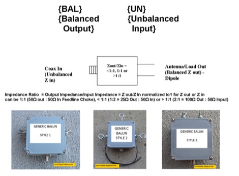 If you ever asked if you need an Unun or a Balun this article is for you. The right question should be do I need a feed line choke or an impedance transformer whose output is configured as balanced or as unbalanced. An impedance transformer can be configured as a voltage transformer or as a current transformer.
 -
 The **LDG Z100 Autotuner** review by GW6ITJ details the unit's practical application and performance in a ham shack environment. Initially acquired to replace an MFJ-902, the Z100 is noted for its ease of use, though the author observes it doesn't quite match the impedance range of the older MFJ unit. This hands-on assessment provides a real-world perspective on its capabilities for 100-watt operation across the HF bands. GW6ITJ specifically mentions the Z100's suitability for 3.5 MHz and higher frequencies, indicating its utility for common HF operations. The review focuses on user experience rather than technical specifications, directing readers to the LDG website for detailed data and manuals. This approach highlights the tuner's operational characteristics from a user's perspective. The author's experience with the Z100 suggests it's a reliable choice for general amateur radio use, particularly for those seeking a straightforward autotuner. The comparison to the MFJ-902 offers a valuable benchmark for hams considering a similar upgrade or new acquisition, emphasizing practical differences in impedance matching.
 -
 Designing and constructing a two-element receiving loop antenna array for HF operation involves specific considerations for achieving high directivity and noise reduction. This resource details a homebrew system comprising two 30-inch diamond-shaped loops, spaced 20 feet apart, which are fed through mast-mounted preamplifiers and passive signal combiners. The operational principle relies on adjusting phase delays between elements via precise _Belden 8241_ coaxial cable lengths, optimized for specific bands from 160m to 20m. Performance data, derived from _EZ-NEC_ modeling, illustrates consistent 90° azimuth-plane beamwidth and low take-off angles across the target bands, with _Receiving Directivity Factor_ (RDF) values comparable to a 300-foot Beverage antenna. The article presents detailed elevation and azimuth plots for 20m, 30m, 40m, 80m, and 160m, demonstrating the array's ability to provide strong response at low DX angles while also supporting _NVIS_ signals. Key components like the _DX Engineering RPA-1_ preamplifier and _DXE RSC-2_ signal combiner are discussed, alongside the importance of impedance matching to preserve antenna patterns. The construction emphasizes self-contained elements that do not require ground radials, offering a compact solution suitable for suburban environments and stealth installations, with a focus on optimizing receive performance independently from transmit antennas.
 -
 Constructing an End-Fed Half-Wave (EFHW) antenna offers a practical solution for HF operators seeking a multiband wire antenna without the need for extensive radial systems. This design typically employs a high-impedance transformer at the feed point, matching the antenna's inherent high impedance to a 50-ohm coaxial feedline. The article specifically details a 2012 approach, focusing on a transformer with a 49:1 turns ratio, which is a common configuration for EFHW antennas. The resource outlines the construction of a wire element cut for a half-wavelength on the lowest desired band, with specific coil arrangements enabling operation on harmonically related bands such as 40m, 20m, and 10m. It discusses the physical dimensions and winding details for the matching transformer, often utilizing a ferrite toroid core to achieve the necessary impedance transformation. The content provides insights into the operational principles and practical considerations for deploying such an antenna, including methods for tuning and optimizing performance across multiple amateur radio bands. While acknowledging that the presented information from 2012 may be superseded by newer insights, it serves as a foundational reference for understanding EFHW antenna theory and construction.
 -
 Coaxial cable stripping for PL-259 connectors requires precise measurements to ensure optimal RF performance and mechanical integrity. For RG-8X, the outer jacket is stripped 1/2 inch, the braid 5/16 inch, and the dielectric 1/8 inch, leaving the center conductor exposed. RG-58 preparation involves a 1/2 inch jacket strip, 1/4 inch braid strip, and 1/8 inch dielectric strip. These specific dimensions facilitate proper soldering and crimping, minimizing impedance discontinuities at the connector interface. Different coaxial cable types, such as RG-8 and RG-213, necessitate varied stripping lengths due to their construction. The _PL-259_ connector, a common UHF type, relies on these exact preparations for a secure fit and low-loss connection. Incorrect stripping can lead to high SWR, RF leakage, and mechanical failure, impacting overall station efficiency. The guide details these critical dimensions for several popular coax cables. Using a dedicated _coax stripper_ tool or precise measurements with a utility knife improves consistency.
 -
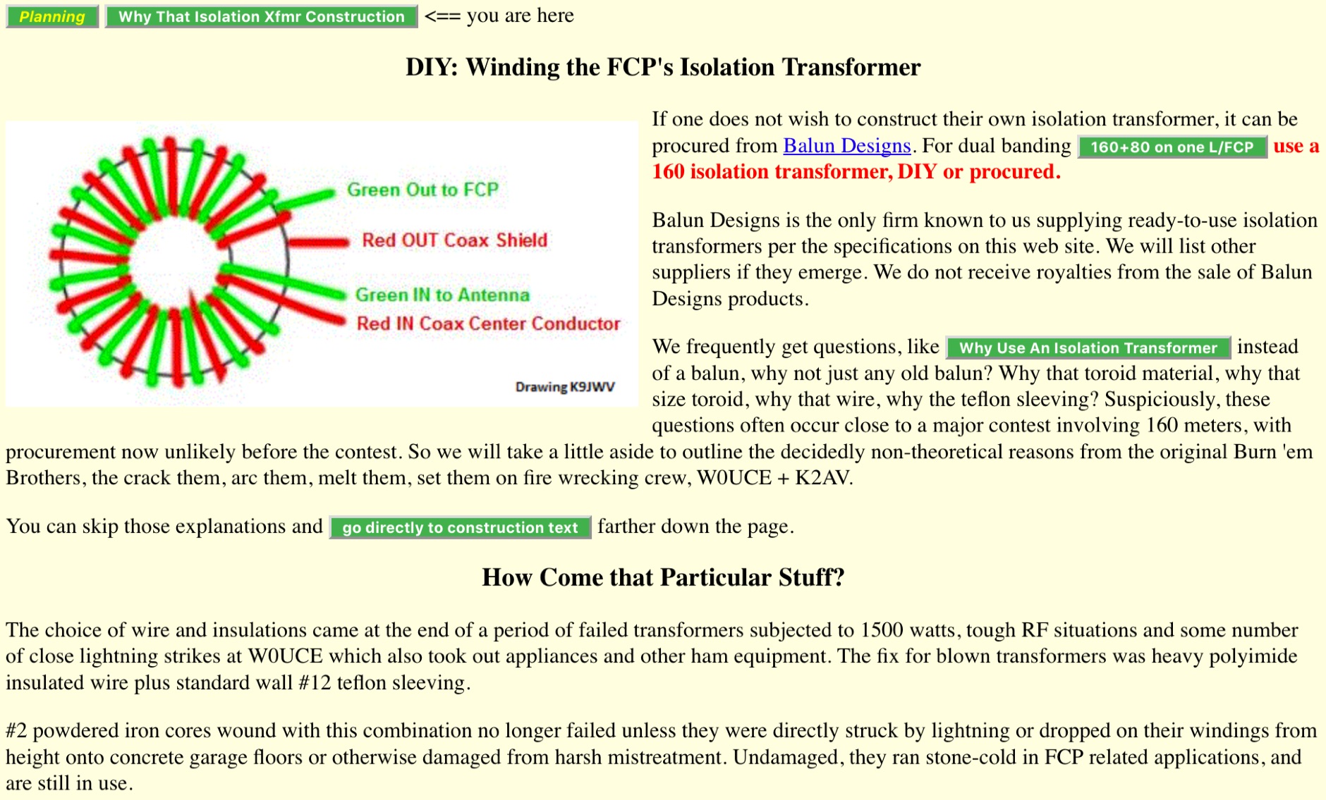 Article about isolation transformer construction to perform optimal impedance matching. Winding the FCP isolation transformer, includes interesting table for Winding Turns and Lengths and Core Configurations for T300 T200 T400 toroids
 -
 AN-SOF is a professional comprehensive software tool for the modeling and simulation of antenna systems. AS-SOF allows to describe antenna geometry, Choose construction materials, Describe the environment and ground conditions, Describe the antenna height above ground, Analize radiation pattern and front-to-back ratio, Plot directivity and gain, Analize input impedance and VSWR,Predict antenna bandwidth
 -
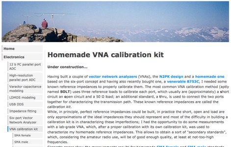 A calibration kit useful when you need known reference impedances to properly calibrate your vector network analyzers.
 -
 Voldatech, a manufacturer based in China, produces a range of RF feeder cables and site components essential for amateur radio installations and telecommunication infrastructure. Their product line includes various types of coaxial cables, such as **50 Ohm** and 75 Ohm options, along with a comprehensive selection of connectors like N-type, UHF, and BNC. These components are critical for maintaining signal integrity and minimizing loss in antenna systems, whether for a home shack or a remote DXpedition setup. The company's focus on _RF Coax cables_ and connectors directly supports the needs of radio amateurs seeking reliable transmission lines for their transceivers and antennas. Amateurs often compare Voldatech's offerings to established brands, evaluating factors such as impedance matching, shielding effectiveness, and durability under various environmental conditions. The availability of diverse cable types allows operators to select optimal solutions for different frequency bands and power levels, from QRP to high-power amplifier setups. Their products are particularly relevant for those constructing new antenna arrays or upgrading existing feedline systems, aiming to achieve maximum power transfer and reduce standing wave ratio (SWR) for efficient signal propagation.
 -
 The ARRL's End-Fed Half-Wave (EFHW) Antenna Kit is an easy-to-build four-band antenna designed for 10, 15, 20, and 40 meters. Ideal for portable operations, it includes a 49:1 impedance transformer for compatibility with most transceivers. This project, detailed with step-by-step assembly instructions, involves creating a weatherproof enclosure and impedance matching network. The kit simplifies HF operations and supports multiple configurations, making it a versatile tool for amateur radio opertors.
 -
 Documents S21RC's construction of an impedance transformer harness for a VHF/UHF cross yagi, utilizing 20m of _RG179_ cable. Details the creation of a DIY RF sampler with a -50dB sampling output, primarily for measuring HF radio PA section output with a Spectrum Analyzer, also applicable for _Pure Signal_ transmission. Chronicles the deployment of a 200m long beverage antenna for the _S21DX IOTA_ operation in 2022, positioned 2m above ground. Discusses the construction of a 3-element short beam for 10m to replace a previous 2-element antenna, with assistance from S21DW. Provides guidance on operating cheap _PA-70_ and _PA-100_ type Chinese SSPAs using IRF530 MOSFETs, emphasizing the necessity of a final LPF. Outlines the design and construction of a fully isolated interface for radio-to-computer connections, supporting various digital modes with isolated ground, audio transformers for IN/OUT, optical isolation for CAT/CIV, and isolated PTT/COS lines. Includes a log of software updates, such as the _HMI/TFT for NX8048K070_ and _2.1.14 Lite_ release with bug fixes for PEP hold and gradual watt decay.
 -
 The CobWebb antenna project is a compact, multiband HF solution ideal for amateur radio operators. Covering 14-28 MHz, it features a square dipole array with near-omnidirectional coverage and unity gain. This guide details a DIY approach, using a 1:4 current balun for impedance matching. Construction involves aluminum and fiberglass tubing, with optimized element tuning for SWR performance. Weather resistance improvements and resonance shift considerations are also discussed. Build your own CobWebb antenna for an efficient, space-saving HF experience.
 -
 Messi & Paoloni offers a range of RF coaxial cables, including the _Ultraflex_ series, specifically engineered for amateur radio applications. These cables feature advanced dielectric materials and high-density braiding, resulting in significantly reduced attenuation across HF, VHF, and UHF bands. For instance, the Ultraflex 7 exhibits a loss of only **2.5 dB per 100 feet** at 144 MHz, making it suitable for demanding DX and contesting operations. The company's product line also includes specialized connectors, such as N-type and PL-259, designed to maintain optimal impedance matching and minimize signal reflections. Each connector is precision-machined to ensure a secure, weather-resistant termination, crucial for outdoor antenna installations and long-term reliability. Messi & Paoloni emphasizes rigorous quality control, with all cables undergoing testing to ensure consistent performance and durability, supporting effective two-way radio communication.
 -
 Microwaves101 provides an extensive repository of information covering fundamental principles of microwave design, targeting engineers and radio amateurs interested in the higher frequency spectrum. The site features a detailed _encyclopedia_ of microwave terms and concepts, alongside practical design considerations for various components and systems. It serves as a foundational reference for understanding RF propagation, transmission lines, and active/passive microwave circuits. The resource includes numerous calculators for impedance matching, filter design, and other critical RF parameters, facilitating hands-on project development. Discussions on **10 GHz** equipment and **24 GHz** projects highlight practical amateur radio applications, extending to operations up to 134 GHz. Content spans from basic theory to advanced topics like MMIC design and antenna characteristics, supporting both educational and practical endeavors in microwave technology.
 -
 Details Amphenol Connex's product range, focusing on RF connectors, adapters, and cable assemblies. The company produces common radio frequency interfaces such as _BNC_, _SMA_, and _TNC_ connectors, alongside numerous other specialized designs. These components are critical for establishing reliable signal paths in amateur radio stations, ensuring proper impedance matching and minimal signal loss across various frequency bands. The manufacturing process emphasizes precision engineering to meet the demanding specifications of RF applications, from HF to microwave frequencies. Product lines support diverse coaxial cable types, facilitating custom cable assembly for specific station configurations. The extensive catalog provides solutions for both fixed station installations and portable operations, addressing the needs of contesters, DXers, and general amateur radio operators.
 -
 Presents Wayne Kerr Electronics, a manufacturer specializing in precision component measurement products. The company offers a range of LCR meters, impedance analyzers, and transformer test systems designed for various applications in electronics manufacturing and research. Specific product lines include the 3260B Precision Magnetics Analyzer, which measures inductance, capacitance, and resistance with high accuracy, and the 6500B series of LCR meters, capable of testing components across a broad frequency range up to 120 MHz. The 3255B and 3265B series provide solutions for transformer and inductor testing, including turns ratio, leakage inductance, and inter-winding capacitance measurements. These instruments are utilized in quality control, component characterization, and production line testing, ensuring performance and reliability in electronic circuits. Wayne Kerr's offerings support engineers and technicians in verifying component specifications.
 -
 Building an End-Fed Half-Wave (EFHW) antenna from a kit, as detailed by Frank Bontenbal, PA2DKW, with process photos by Bob Inderbitzen, NQ1R, offers a practical approach for hams. This specific kit, a collaboration between ARRL and HF Kits, targets 10, 15, 20, and 40 meters, making it a versatile option for HF operations. Unlike a center-fed dipole, the EFHW is a half-wavelength antenna fed at one end, which simplifies deployment, particularly for portable use. The construction guide meticulously outlines the assembly of the 49:1 impedance matching network, crucial for transforming the antenna's high impedance (around 2,500 Ohms) to a transceiver-friendly 50 Ohms. Steps include preparing the enclosure by drilling holes for the coaxial connector and antenna connections, followed by the precise winding of enameled copper wire onto a toroid to create the transformer. The guide emphasizes careful insulation removal and soldering for reliable connections. Final assembly involves integrating a 100 pF capacitor for higher band compensation, soldering the transformer's primary and secondary sides, and conducting SWR tests with a 2K7 resistor or a half-wavelength wire. The document also provides examples of wire lengths for different bands, such as 16 feet for 10 meters or 66 feet for 40 meters, demonstrating the transformer's adaptability for various half-wavelength configurations.
 -
 LZ1AQ describes a versatile QRP antenna tuner that switches between Pi and Tee configurations with a single toggle. Using two variable capacitors and a seven-switch stepped inductor providing 128 increments (0.16 to 18.7 uH), this compact design handles 3.5 to 28 MHz with excellent matching range. The Pi mode works best for certain impedances while Tee mode proves more universal, matching loads the Pi cannot. Built in a plastic enclosure using salvaged radio capacitors, the tuner operates reliably up to 100 watts with proper antennas, though it's optimized for QRP service with random wires.
 -
 The _G3TSO_ Mobile Antenna Page details construction and tuning methods for mobile antennas operating across **10 to 160 metres**. The content describes a Hustler-based design, optimized for RF performance and vehicle speeds, featuring centre loading. For optimal operation on various bands, the loading coil placement requires clearance from the vehicle body. Antenna resonance is critical for efficient mobile operation. A mobile antenna's base impedance may be as low as 27 ohms, requiring specific matching to achieve maximum radiation, as a minimum SWR at the transmitter does not always indicate resonance or maximum output. Tuning involves physical adjustment of antenna length to achieve resonance at the operating frequency. The _G3TSO_ page outlines a tuning procedure utilizing a low-power signal source and a field strength meter to identify maximum radiation before impedance matching. Loading coil placement, either at the base, center, or top of the antenna, influences radiation efficiency and mechanical stability for mobile installations. Centre-loaded whips, such as the Hustler design, offer a compromise between efficiency and stability, often for single-band operation. Helically wound antennas, including those for **28 MHz**, may present base impedances around 17 ohms, resulting in a 3:1 SWR at resonance. Low resistance grounding at the antenna base is also specified for optimizing performance and minimizing RFI during mobile operation. DXZone Focus: Mobile | Any | Antenna Tuning | HF
 -
 In this article, Steve G0UIH presents a straightforward guide for constructing a lightweight 15m 3 Element Yagi antenna with impressive performance metrics. With a focus on ease of construction and efficiency, the design boasts a nearly 8.2dbi forward gain and 30db front to back ratio. Utilizing readily available materials and a hairpin match for impedance matching, this Yagi offers broad bandwidth and simple tuning for optimal operation across the 15m band.
 -
 The HB9CV antenna calculator aids amateur radio enthusiasts in designing antennas for VHF and UHF bands. By inputting the working frequency, users can obtain crucial dimensions like dipole lengths and distances. The tool, based on the HFSS antenna model, provides data on impedance, VSWR, and gain, optimizing front/back radiation ratios. It includes tips for fine-tuning using a Г-matching balun and compensating capacitor, ensuring effective performance and minimal VSWR for enhanced radio communications and direction finding.
 -
 Integrating a **160-meter vertical wire antenna** with an existing 80-meter Yagi system presents unique challenges for Top Band operation. This project outlines the author's experiences with seasonal antenna removal and reinstallation, a necessary task for agricultural land use. It details specific issues encountered, such as incorrect coil sizing and relay configuration problems, providing practical insights into common pitfalls. The article describes the iterative tuning process, comparing **NEC model** predictions with actual on-air performance. It emphasizes the importance of precise measurements and adjustments to achieve optimal resonance and impedance matching. The author shares lessons learned from troubleshooting, including the impact of ground system integrity and feedline considerations. Concluding with an antenna checkup, the resource addresses long-term maintenance aspects, including galvanic corrosion prevention and general upkeep for reliable operation.
 -
 A medium power End Fed Half Wave Antenna coupler, specifically tuned to the QRP frequency of 7030 kHz. Constructed from coil stock and capacitors, it achieves an impedance ratio of 64:1. The coupler has proven effective for power ranges from 2 to 100 Watts on the 40m band.
 -
 This article presents the C-Pole antenna project, a compact, ground-independent vertical antenna designed for amateur radio operators. It features a folded half-wave dipole configuration that eliminates the need for radials, making it suitable for various locations, especially in deed-restricted areas. The C-Pole offers efficient performance with a 2:1 SWR bandwidth of approximately 3%, and it can be easily constructed using common materials. Additionally, the article discusses practical aspects such as feed-point impedance transformation and balun design to optimize functionality and minimize losses.
 -
 WB8LZR details the construction and initial field results of a multi-band vertical wire antenna, designed to complement his existing horizontal loop for improved DX on 80 meters. The antenna utilizes a 67-foot vertical wire, configured as a quarter-wave radiator on 80m, and employs a 1:1 current balun for RF isolation on 80m, 30m, and 17m. For bands like 40m, 20m, and 10m, where the wire acts as a half-wave or full-wave radiator, an additional impedance transforming _unun_ is integrated to manage the significantly higher feedpoint impedance and voltage. The author notes the vertical's performance as a receiving antenna, observing reduced noise compared to his main horizontal loop, particularly on 80m, and even hearing some long-path signals the loop missed. Initial QRP contacts, including a **1-watt** QSO with a _VP2 station_ on 30m, demonstrate its transmit capability. While the radial system is currently rudimentary, the project outlines practical considerations for multi-band vertical deployment and impedance matching.
 -
 A small magnetic loop antenna, often employed by hams facing antenna restrictions or high local RFI, offers a compact solution for HF operation. This resource details the construction of a foldable magnetic loop designed for the 40m through 17m bands, emphasizing its high-Q factor and _Faraday coupling_ for effective noise rejection and narrow-band filtering. The guide outlines material selection, advocating for copper over aluminum to maximize efficiency, and provides insights into the physics governing its operation, including impedance matching and resonance principles. Practical application of this antenna design is particularly beneficial for QRP enthusiasts and portable operators seeking a stealthy, high-performance antenna. The construction process includes specific details for a 1-meter diameter loop, a 140pF variable capacitor, and a _gamma match_ for impedance transformation. Performance comparisons suggest that while a full-size dipole might offer slightly better gain, the magnetic loop's ability to mitigate local noise often results in a superior signal-to-noise ratio, making it a viable option for challenging RF environments.
 -
 The mini Radio Solutions miniVNA PRO is the only affordable vector network analyser (VNA) I know of that offers remote wireless operation. This is very interesting because it allows to measure the input impedance of HF antennas installed at height without having to deal with coax cable lengths, baluns nor common mode suppression chokes. However, to render the miniVNA PRO truly field proof, it requires a number of significant modifications.